
Related Manuals for Nokia RM-51


Summary of Contents for Nokia RM-51
- Page 1 Nokia Customer Care Service Manual RM-51 (Nokia 3230) Mobile Terminal Part No: (9238460 (Issue 1)) Company Confidential Copyright ©2005 Nokia. All Rights Reserved.
- Page 2 RM-51 Nokia Customer Care Amendment Record Sheet Amendment Record Sheet Amendment No Date Inserted By Comments Original issue 02/2005 Johanna Bryman Page ii Company Confidential 9238460 (Issue 1) Copyright ©2005 Nokia. All Rights Reserved.
- Page 3 Nokia operates a policy of continuous development. Nokia reserves the right to make changes and improvements to any of the products described in this document without prior notice. Under no circumstances shall Nokia be responsible for any loss of data or income or any special, incidental, consequential or indirect damages howsoever caused.
- Page 4 WCDMA networks and cause problems to 3G cellular phone communication in a wide area. • During testing never activate the GSM or WCDMA transmitter without a proper antenna load, otherwise GSM or WCDMA PA may be damaged. Page iv Company Confidential 9238460 (Issue 1) Copyright ©2005 Nokia. All Rights Reserved.
- Page 5 Use only approved accessories and batteries. Do not connect incompatible products. CONNECTING TO OTHER DEVICES When connecting to any other device, read its user’s guide for detailed safety instructions. Do not connect incompatible products. 9238460 (Issue 1) Company Confidential Page v Copyright ©2005 Nokia. All Rights Reserved.
- Page 6 All of the above suggestions apply equally to the product, battery, charger or any accessory. Page vi Company Confidential 9238460 (Issue 1) Copyright ©2005 Nokia. All Rights Reserved.
- Page 7 Nokia Customer Care ESD protection Nokia requires that service points have sufficient ESD protection (against static electricity) when servicing the phone. Any product of which the covers are removed must be handled with ESD protection. The SIM card can be replaced without ESD protection if the product is otherwise ready for use.
- Page 8 Do not dispose of batteries in a fire! Dispose of batteries according to local regulations (e.g. recycling). Do not dispose as household waste. Page viii Company Confidential 9238460 (Issue 1) Copyright ©2005 Nokia. All Rights Reserved.
- Page 9 While every endeavour has been made to ensure the accuracy of this document, some errors may exist. If any errors are found by the reader, NOKIA MOBILE PHONES Business Group should be notified in writing. Please state: • Title of the Document + Issue Number/Date of publication •...
- Page 10 RM-51 Nokia Customer Care Company Policy (This page left intentionally blank.) Page x Company Confidential 9238460 (Issue 1) Copyright ©2005 Nokia. All Rights Reserved.
- Page 11 4 Service Tools 5 Disassembly and reassembly instructions 6 Baseband troubleshooting 7 RF troubleshooting 8 Camera module troubleshooting 9 System module and user interface 10 Schematics Glossary 9238460 (Issue 1) Company Confidential Page xi Copyright ©2005 Nokia. All Rights Reserved.
- Page 12 RM-51 Nokia Customer Care Nokia 3230 Service Manual Structure (This page left intentionally blank.) Page xii Company Confidential 9238460 (Issue 1) Copyright ©2005 Nokia. All Rights Reserved.
- Page 13 Nokia Customer Care 1 — General information 9238460 (Issue 1) Company Confidential Page 1–1 Copyright ©2005 Nokia. All Rights Reserved.
- Page 14 RM-51 Nokia Customer Care General information (This page left intentionally blank.) Page 1–2 Company Confidential 9238460 (Issue 1) Copyright ©2005 Nokia. All Rights Reserved.
-
Page 15: Table Of Contents
Software features..................................1–6 UI features....................................1–6 Mobile enhancements..................................1–7 Technical specifications................................1–9 General specifications................................1–9 Main RF characteristics for triple-band phones (Europe)....................1–9 Battery endurance...................................1–9 Environmental conditions..............................1–10 List of Figures Figure 1 RM-51....................................1–5 9238460 (Issue 1) Company Confidential Page 1–3 Copyright ©2005 Nokia. All Rights Reserved. - Page 16 RM-51 Nokia Customer Care General information (This page left intentionally blank.) Page 1–4 Company Confidential 9238460 (Issue 1) Copyright ©2005 Nokia. All Rights Reserved.
-
Page 17: Product Selection
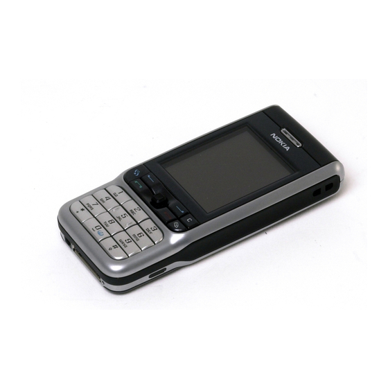
RM-51 General information Nokia Customer Care Product selection The RM-51 is a triple band transceiver unit designed for the GSM900 (including EGSM), GSM1800 and GSM1900 networks. Figure 1 RM-51 Display and keypad features • Large high resolution TFT color display (176x208 pixels) with 65,536 colors •... -
Page 18: Software Features
• Moblogging • Contacts with thumbnail images • Presence Enhanced Contact • Calendar • To-do list • Notes • Voice Recorder • Calculator • Clock • Converter Page 1–6 Company Confidential 9238460 (Issue 1) Copyright ©2005 Nokia. All Rights Reserved. -
Page 19: Mobile Enhancements
ACP-12 Mobile charger LCH-12 Car accessories Type Headrest hands free BHF-3 Plug-in car hands free HF-3 Wireless car kit CK-1W Advanced car kit CK-7W Car kit CR-10 9238460 (Issue 1) Company Confidential Page 1–7 Copyright ©2005 Nokia. All Rights Reserved. - Page 20 Memory unit MU-2 Memory unit MU-9 Memory unit MU-12 Imaging accessories Type Image album PD-1 Messaging accessories Type Digital pen SU-1B Wireless keyboard SU-8W Wireless GPS module LD-1W Page 1–8 Company Confidential 9238460 (Issue 1) Copyright ©2005 Nokia. All Rights Reserved.
-
Page 21: Technical Specifications
Channel spacing 200KHz Number of Tx power levels GSM900: 15 GSM1800: 16 GSM1900: 16 Battery endurance Nokia measurements of operation times in GSM900/1800 Talk time Battery: BL-5B 760mAh Up to 2,5-4 hours 9238460 (Issue 1) Company Confidential Page 1–9 Copyright ©2005 Nokia. All Rights Reserved. -
Page 22: Environmental Conditions
Condensed or dripping water may cause intermittent malfunctions. Protection against dripping water has to be implemented in (enclosure) mechanics. Continuous dampness will cause permanent damage to the module. Page 1–10 Company Confidential 9238460 (Issue 1) Copyright ©2005 Nokia. All Rights Reserved. - Page 23 Nokia Customer Care 2 — Parts and layouts 9238460 (Issue 1) Company Confidential Page 2–1 Copyright ©2005 Nokia. All Rights Reserved.
- Page 24 RM-51 Nokia Customer Care Parts and layouts (This page left intentionally blank.) Page 2–2 Company Confidential 9238460 (Issue 1) Copyright ©2005 Nokia. All Rights Reserved.
- Page 25 Component parts list..................................2–9 Component layouts..................................2–23 List of Tables Table 1 Mechanical parts list...............................2–7 List of Figures Figure 2 Exploded view of Nokia RM-51..........................2–5 Figure 3 Spare parts overview..............................2–6 Figure 4 Component layout, bottom............................2–24 Figure 5 Component layout, top..............................2–24 9238460 (Issue 1) Company Confidential Page 2–3...
- Page 26 RM-51 Nokia Customer Care Parts and layouts (This page left intentionally blank.) Page 2–4 Company Confidential 9238460 (Issue 1) Copyright ©2005 Nokia. All Rights Reserved.
-
Page 27: Exploded View Of Nokia Rm-51
RM-51 Parts and layouts Nokia Customer Care Exploded view of Nokia RM-51 Figure 2 Exploded view of Nokia RM-51 Spare parts overview 9238460 (Issue 1) Company Confidential Page 2–5 Copyright ©2005 Nokia. All Rights Reserved. -
Page 28: Swap Units
RM-51 Nokia Customer Care Parts and layouts Figure 3 Spare parts overview SWAP units SWAP units RM-51 SWAP EURO1 - BLACK RM-51 SWAP EURO1 - ORANGE Page 2–6 Company Confidential 9238460 (Issue 1) Copyright ©2005 Nokia. All Rights Reserved. -
Page 29: Mechanical Parts
RM-51 Parts and layouts Nokia Customer Care SWAP units RM-51 SWAP EURO1 - RED RM-51 SWAP FRANCE - BLACK RM-51 SWAP FRANCE - ORANGE RM-51 SWAP FRANCE - RED RM-51 SWAP GREECE - BLACK RM-51 SWAP GREECE - ORANGE RM-51 SWAP GREECE - RED... - Page 30 UI BOARD I021 B2B FLEX MODULE I022 SHIELD I023 CAMERA I024 ENGINE MODULE ANTENNA ASSY I025 IHF CHAMBER I026 IHF SPEAKER I027 ANTENNA D-COVER ASSY I028 VIBRA Page 2–8 Company Confidential 9238460 (Issue 1) Copyright ©2005 Nokia. All Rights Reserved.
-
Page 31: Component Parts List
C199 Ceramic Capacitor CHIPCAP X5R 2U2 K 6V3 0603 C200 Ceramic Capacitor CHIPCAP X7R 330P J 50V 0402 C201 Ceramic Capacitor CHIPCAP X7R 10N K 16V 0402 9238460 (Issue 1) Company Confidential Page 2–9 Copyright ©2005 Nokia. All Rights Reserved. - Page 32 C269 Ceramic Capacitor CHIPCAP X5R 100N K 10V 0402 C270 Ceramic Capacitor CHIPCAP NP0 270P J 50V 0402 C271 Ceramic Capacitor CHIPCAP X7R 10N K 16V 0402 Page 2–10 Company Confidential 9238460 (Issue 1) Copyright ©2005 Nokia. All Rights Reserved.
- Page 33 C312 Ceramic Capacitor CHIPCAP X5R 100N K 10V 0402 C314 Ceramic Capacitor CHIPCAP X5R 1U K 6V3 0603 C315 Ceramic Capacitor CHIPCAP X5R 2U2 K 10V 0805 9238460 (Issue 1) Company Confidential Page 2–11 Copyright ©2005 Nokia. All Rights Reserved.
- Page 34 C443 Ceramic Capacitor CHIPCAP X5R 100N K 10V 0402 C444 Ceramic Capacitor CHIPCAP X5R 1U K 16V 0603 C445 Ceramic Capacitor CHIPCAP NP0 22P J 50V 0402 Page 2–12 Company Confidential 9238460 (Issue 1) Copyright ©2005 Nokia. All Rights Reserved.
- Page 35 Ceramic Capacitor CHIPCAP X5R 100N K 10V 0402 C522 Ceramic Capacitor CHIPCAP X7R 10N K 16V 0402 C523 Ceramic Capacitor CHIP ARRAY NP0 4X470P J 16V 0612 9238460 (Issue 1) Company Confidential Page 2–13 Copyright ©2005 Nokia. All Rights Reserved.
- Page 36 C658 Ceramic Capacitor CHIPCAP X7R 47N K 10V 0402 C659 Ceramic Capacitor CHIPCAP X7R 22N K 16V 0402 C661 Ceramic Capacitor CHIPCAP X7R 1N0 K 50V 0402 Page 2–14 Company Confidential 9238460 (Issue 1) Copyright ©2005 Nokia. All Rights Reserved.
- Page 37 C712 Ceramic Capacitor CHIPCAP X7R 10N K 16V 0402 C713 Ceramic Capacitor CHIPCAP NP0 15P J 50V 0402 C714 Ceramic Capacitor CHIPCAP NP0 15P J 50V 0402 9238460 (Issue 1) Company Confidential Page 2–15 Copyright ©2005 Nokia. All Rights Reserved.
- Page 38 Interface IC KAEDE V1.0 ISP1182 HVQFN32 D460 NOR 128M + 128M 1.8/1.8V FGBA44 P D461 SDRAM NMP 128MBIT 133MHZ PBFREE D462 FLASH Memory FLASH 4MX16 1V8/1V8 VFBGA44 PBFRE Page 2–16 Company Confidential 9238460 (Issue 1) Copyright ©2005 Nokia. All Rights Reserved.
- Page 39 L656 Fixed Inductor CHIP COIL 33N G Q40/250MHZ 0603 L657 Fixed Inductor CHIP COIL 33N G Q40/250MHZ 0603 L658 Fixed Inductor CHIP COIL 120N J Q16/100MHZ 0603 9238460 (Issue 1) Company Confidential Page 2–17 Copyright ©2005 Nokia. All Rights Reserved.
- Page 40 CHIPRES 0W06 100K J 0402 R192 Fixed Resistor CHIPRES 0W06 2K7 J 0402 R193 Fixed Resistor CHIPRES 0W06 10K J 0402 R194 Fixed Resistor CHIPRES 0W06 2R2 J 0402 Page 2–18 Company Confidential 9238460 (Issue 1) Copyright ©2005 Nokia. All Rights Reserved.
- Page 41 CHIPRES 0W06 33R J 0402 R447 Fixed Resistor CHIPRES 0W06 68R J 0402 R448 Fixed Resistor CHIPRES 0W06 68R J 0402 R450 Variable Resistor CHIP VARISTOR VWM15V VC50V 0402 9238460 (Issue 1) Company Confidential Page 2–19 Copyright ©2005 Nokia. All Rights Reserved.
- Page 42 CHIPRES 0W06 1K0 J 0402 R630 Fixed Resistor CHIPRES 0W06 1K0 J 0402 R631 Fixed Resistor CHIPRES 0W06 100K J 0402 R634 Resistor Network RES NETWORK 0W06 2X10R J 0404 Page 2–20 Company Confidential 9238460 (Issue 1) Copyright ©2005 Nokia. All Rights Reserved.
- Page 43 CHIPRES 0W06 1K0 J 0402 R702 Fixed Resistor CHIPRES 0W06 4K7 J 0402 R703 Fixed Resistor CHIPRES JUMPER 0R0 0402 R713 Fixed Resistor CHIPRES 0W06 33R J 0402 9238460 (Issue 1) Company Confidential Page 2–21 Copyright ©2005 Nokia. All Rights Reserved.
- Page 44 Diode SCH DIODE 30V 200MA VF 0V5 SOD523 Bipolar Transistor V615 TR 2SC5658QRS N 50V 0A1 0W15 VMT3 V656 Diode CAP.DI BB202 CT 2.5 FM 0R8 SOD523 Page 2–22 Company Confidential 9238460 (Issue 1) Copyright ©2005 Nokia. All Rights Reserved.
-
Page 45: Component Layouts
SAW FILT 942.5+-17.5MHZ/3DB 2X1.6 Integrated Z814 Discretes ASIP 10-CH ESD EMI FILTER BGA25 Component layouts Note: See also A3 size layouts in Schematics chapter: bottom (Page ) top (Page 9238460 (Issue 1) Company Confidential Page 2–23 Copyright ©2005 Nokia. All Rights Reserved. - Page 46 RM-51 Nokia Customer Care Parts and layouts Component layout, bottom Figure 4 Component layout, bottom Component layout, top Figure 5 Component layout, top Page 2–24 Company Confidential 9238460 (Issue 1) Copyright ©2005 Nokia. All Rights Reserved.
- Page 47 Nokia Customer Care 3 — Phoenix service SW 9238460 (Issue 1) Company Confidential Page 3–1 Copyright ©2005 Nokia. All Rights Reserved.
- Page 48 RM-51 Nokia Customer Care Phoenix service SW (This page left intentionally blank.) Page 3–2 Company Confidential 9238460 (Issue 1) Copyright ©2005 Nokia. All Rights Reserved.
-
Page 49: Table Of Contents
Figure 31 Uninstalling Phoenix data package........................3–20 Figure 32 Finish data package uninstallation........................3–20 Figure 33 Login....................................3–21 Figure 34 Add information for new user 1...........................3–21 Figure 35 Add information for new user 2...........................3–21 9238460 (Issue 1) Company Confidential Page 3–3 Copyright ©2005 Nokia. All Rights Reserved. - Page 50 Figure 68 Finish JBV-1 update installation...........................3–36 Figure 69 Checking JBV-1 SW version.............................3–36 Figure 70 JBV-1 update directory window...........................3–37 Figure 71 JBV-1 SW update done.............................3–37 Figure 72 JBV-1 SW status................................3–37 Page 3–4 Company Confidential 9238460 (Issue 1) Copyright ©2005 Nokia. All Rights Reserved.
-
Page 51: Service Software Installation
• Run the application file (for example, phoenix_service_sw_a15_2004_24_7_55.exe) and follow the instructions on the screen. Note: Administrator rights may be required to be able to install Phoenix depending on the operating system. 9238460 (Issue 1) Company Confidential Page 3–5 Copyright ©2005 Nokia. All Rights Reserved. - Page 52 Press the F1 key or the Help button to activate a Help file. Steps 1. Run the phoenix_service_sw_a15_2004_24_7_55.exe to start installation. Install Shield prepared the setup. Figure 7 Preparing setup Install Shield will prepare. Page 3–6 Company Confidential 9238460 (Issue 1) Copyright ©2005 Nokia. All Rights Reserved.
- Page 53 Phoenix service SW Nokia Customer Care 2. Click Next in Welcome dialog to continue. Figure 8 Welcome dialog 3. Read the disclaimer carefully. Figure 9 Disclaimer text 9238460 (Issue 1) Company Confidential Page 3–7 Copyright ©2005 Nokia. All Rights Reserved.
- Page 54 RM-51 Nokia Customer Care Phoenix service SW 4. Choose destination folder. The default folder C:\ProgramFiles\Nokia\Phoenix is recommended. Then click Next to continue. You may choose another location by selecting Browse (not recommended). Figure 10 Destination folder 5. Wait for the components to be copied. The progress of the setup is shown in the Setup Status window.
- Page 55 If the operating system requires restarting your computer (Windows 98, SE, ME) the Install Shield Wizard will tell you about it. Select Yes... to reboot the PC immediately and No... to reboot the PC manually afterwards. 9238460 (Issue 1) Company Confidential Page 3–9 Copyright ©2005 Nokia. All Rights Reserved.
- Page 56 After the reboot, components are registered and Phoenix is ready for use. Note: Phoenix does not work, if components have not been registered. Figure 15 Registering components 2 Page 3–10 Company Confidential 9238460 (Issue 1) Copyright ©2005 Nokia. All Rights Reserved.
-
Page 57: Phoenix Update Installation
• Driver versions will be checked and updated. When you update Phoenix from old to new version (for example, a14_2004_16_4_47 to a15_2004_24_7_55), the update will take place automatically without uninstallation. 9238460 (Issue 1) Company Confidential Page 3–11 Copyright ©2005 Nokia. All Rights Reserved. -
Page 58: Uninstalling Phoenix
Uninstallation can be done manually from Windows Control Panel -> Add/Remove Programs. Steps 1. Choose Phoenix Service Software -> Add/Remove -> Remove to uninstall Phoenix. Figure 18 Remove program The progress of the uninstallation is shown. Page 3–12 Company Confidential 9238460 (Issue 1) Copyright ©2005 Nokia. All Rights Reserved. - Page 59 Else, Install Shield Wizard will tell you about it. Select Yes... to reboot the PC immediately and No... to reboot the PC manually afterwards. Figure 20 Finish uninstallation 9238460 (Issue 1) Company Confidential Page 3–13 Copyright ©2005 Nokia. All Rights Reserved.
-
Page 60: Repairing Phoenix Installation
2. Select Phoenix Service Software -> Add/Remove. 3. In the following view, choose Repair. Phoenix will now reinstall components and register them. The procedure is the same as in the update installation. Page 3–14 Company Confidential 9238460 (Issue 1) Copyright ©2005 Nokia. All Rights Reserved. -
Page 61: Phoenix Service Software Data Package Overview
• Files for type label printing • Validation file for the faultlog repair data reporting system • All product-specific configuration files for Phoenix Service Software components Data files are stored under C:\Program Files\Nokia\Phoenix (default). 9238460 (Issue 1) Company Confidential Page 3–15... -
Page 62: Installing Phoenix Data Package
1. To start installation, run the application file (for example, RM-51_dp_EA_ v_1_0.exe). 2. Click Next, and wait for the installation files to be extracted. Figure 24 Extracting files Page 3–16 Company Confidential 9238460 (Issue 1) Copyright ©2005 Nokia. All Rights Reserved. - Page 63 In this view you can see the contents of the data package. Read the text carefully. There should be information about the Phoenix version required with this data package. Click Next to continue. Figure 26 Data package setup information 9238460 (Issue 1) Company Confidential Page 3–17 Copyright ©2005 Nokia. All Rights Reserved.
- Page 64 The install shield checks where the Phoenix application is installed and the directory is shown. Click Next to continue. 5. Click Next to start copying the files. Phone model specific files will be installed. Please wait. Figure 28 Start copying files Page 3–18 Company Confidential 9238460 (Issue 1) Copyright ©2005 Nokia. All Rights Reserved.
- Page 65 Phoenix can be used, for example, for flashing phones and printing type labels. But first you must: • configure users, and • manage connections. FLS-4S can be used right away. FPS-8* can be used after updating Flash Update Package files. 9238460 (Issue 1) Company Confidential Page 3–19 Copyright ©2005 Nokia. All Rights Reserved.
-
Page 66: Uninstalling Phoenix Data Package
• Uninstallation can also be done manually from Windows Control Panel -> Add/Remove Programs -> xx-xx (* Phone Data Package). (*= type designator of the phone Next action Run the installation package again to continue installation from the beginning. Page 3–20 Company Confidential 9238460 (Issue 1) Copyright ©2005 Nokia. All Rights Reserved. -
Page 67: Service Software Instructions
Figure 35 Add information for new user 2 A new user is now created. 4. Click OK. You are now able to login with this user name. 9238460 (Issue 1) Company Confidential Page 3–21 Copyright ©2005 Nokia. All Rights Reserved. -
Page 68: Managing Connections In Phoenix
Figure 37 Phoenix icon 2. Choose File -> Manage Connections. Figure 38 Manage connections Existing connections can be selected, edited, deleted, and new ones created by using this dialog. Page 3–22 Company Confidential 9238460 (Issue 1) Copyright ©2005 Nokia. All Rights Reserved. - Page 69 • COM Port: Virtual COM Port used by FLS-4 Note: ALWAYS check this. Go to Windows -> Control Panel -> FLS Virtual Port -> Configuration. Figure 41 FLS virtual port icon 9238460 (Issue 1) Company Confidential Page 3–23 Copyright ©2005 Nokia. All Rights Reserved.
- Page 70 When a product is found, Phoenix will load product support. Name of the loaded product support module and its version information will be shown on the bottom of the screen. Page 3–24 Company Confidential 9238460 (Issue 1) Copyright ©2005 Nokia. All Rights Reserved.
-
Page 71: Installing Flash Support Files For Fps-8* And Fls-4
SW update (Page 3–28) after installing a new phone data package. Steps 1. Start by double clicking flash_update_03_13_001.exe to begin installation. Figure 46 Flash update welcome dialog 9238460 (Issue 1) Company Confidential Page 3–25 Copyright ©2005 Nokia. All Rights Reserved. - Page 72 Figure 48 Flash installation interrupted If an older version exists on your PC and it needs to be updated, click Next to continue installation. Figure 49 Continue flash update Page 3–26 Company Confidential 9238460 (Issue 1) Copyright ©2005 Nokia. All Rights Reserved.
- Page 73 RM-51 Phoenix service SW Nokia Customer Care 3. It is highly recommended to install the files to the default destination folder C:\Program Files\Nokia \Phoenix. Click Next to continue. Figure 50 Flash destination folder When installing the flash update files for the first time you may choose another location by selecting Browse.
-
Page 74: Updating Fps-8 Flash Prommer Software
1. Start Phoenix Service Software and log in, manage connection correctly for the FPS-8* flash prommer. Figure 53 Phoenix icon 2. Choose Flashing -> FPS-8 maintenance. Figure 54 FPS-8 maintenance Page 3–28 Company Confidential 9238460 (Issue 1) Copyright ©2005 Nokia. All Rights Reserved. - Page 75 4. Wait until you are notified that update has been successful; the procedure will take a couple of minutes. Click OK to close the FPS-8 Maintenance window. Figure 56 Prommer SW update done View after successful prommer software update: 9238460 (Issue 1) Company Confidential Page 3–29 Copyright ©2005 Nokia. All Rights Reserved.
-
Page 76: Activating Fps-8
Before FPS-8 can be successfully used for phone programming, it must first be activated. Fill in first the FPS-8 activation request sheet in the FPS-8 sales package and follow the instructions on the sheet (included in sales package CD-ROM or from partner web site). Page 3–30 Company Confidential 9238460 (Issue 1) Copyright ©2005 Nokia. All Rights Reserved. - Page 77 RM-51 Phoenix service SW Nokia Customer Care When activation file is received (for example, 00000.in), copy it to C:\ProgramFiles\Nokia\Phoenix \BoxActivation directory on your computer (this directory is created when Phoenix is installed). Steps 1. Start Phoenix Service Software. 2. Select Flashing -> FPS-8 maintenance.
-
Page 78: Deactivating Fps-8
3. In the Prommer Maintenance window, click Deactivate. 4. To confirm the deactivation, click Yes. Figure 62 Deactivation warning The box is deactivated. 5. To complete the deactivation, restart FPS-8. Page 3–32 Company Confidential 9238460 (Issue 1) Copyright ©2005 Nokia. All Rights Reserved. -
Page 79: Updating Jbv-1 Docking Station Software
Note: DO NOT CONNECT THE USB CABLE/JBV-1 TO YOUR COMPUTER YET! Figure 63 Extracting JBV-1 update files Files needed for JBV-1 package setup program will be extracted. 9238460 (Issue 1) Company Confidential Page 3–33 Copyright ©2005 Nokia. All Rights Reserved. - Page 80 Accept the suggested destination folder for installing the JBV-1 SW Package, and click Next to continue. Figure 65 JBV-1 update destination folder Select Full installation and click Next to continue. Page 3–34 Company Confidential 9238460 (Issue 1) Copyright ©2005 Nokia. All Rights Reserved.
- Page 81 Nokia Customer Care Figure 66 Select installation: Full A program folder is created and the software files are installed there. Click Next to continue. Figure 67 Select program folder 9238460 (Issue 1) Company Confidential Page 3–35 Copyright ©2005 Nokia. All Rights Reserved.
- Page 82 • If there is a previously installed JBV-1 Firmware update package (v.17 or older) on your computer, please update the JBV-1 USB driver. Please see the readme.txt file in C:\Program Files\Nokia\JBV-1 Firmware Update\JBV-1USB driver folder for instructions on how to update the JBV-1 USB Driver.
- Page 83 First, click Refresh Status to see the current SW version and then Update Firmware to update the software. After you have updated all docking stations, close the JBV-1 Firmware Update dialog box. 9238460 (Issue 1) Company Confidential Page 3–37 Copyright ©2005 Nokia. All Rights Reserved.
- Page 84 RM-51 Nokia Customer Care Phoenix service SW (This page left intentionally blank.) Page 3–38 Company Confidential 9238460 (Issue 1) Copyright ©2005 Nokia. All Rights Reserved.
- Page 85 Nokia Customer Care 4 — Service Tools 9238460 (Issue 1) Company Confidential Page 4–1 Copyright ©2005 Nokia. All Rights Reserved.
- Page 86 RM-51 Nokia Customer Care Service Tools (This page left intentionally blank.) Page 4–2 Company Confidential 9238460 (Issue 1) Copyright ©2005 Nokia. All Rights Reserved.
- Page 87 POS flash concept with FPS-10............................4–23 Module jig flash concept with FPS-8..........................4–24 Module jig service concept..............................4–25 JBV-1 service concept................................4–25 List of Tables Table 2 TX (dB)....................................4–12 Table 3 RX (db)....................................4–12 9238460 (Issue 1) Company Confidential Page 4–3 Copyright ©2005 Nokia. All Rights Reserved.
- Page 88 Figure 77 JBV-1 flash concept with FPS-8..........................4–22 Figure 78 POS flash concept with FPS-10..........................4–23 Figure 79 Module jig flash concept with FPS-8........................4–24 Figure 80 Module jig service concept.............................4–25 Figure 81 JBV-1 service concept...............................4–26 Page 4–4 Company Confidential 9238460 (Issue 1) Copyright ©2005 Nokia. All Rights Reserved.
-
Page 89: Service Tools
The AXS-4 D9-D9 service cable is used to connect two 9 pin D connectors for example between PC and FPS-8. The cable length is 2 meters. CA-10DS Bi-directional Parallel 0730298 Cable Bi-Directional parallel cable included in FPS-8 sales pack. 9238460 (Issue 1) Company Confidential Page 4–5 Copyright ©2005 Nokia. All Rights Reserved. - Page 90 Old SCB-3 can be used as well. DA-44 Docking station 0780414 adapter DA-44 is used together with JBV-1 as one unit. The adapter makes signal connections to the phone. Page 4–6 Company Confidential 9238460 (Issue 1) Copyright ©2005 Nokia. All Rights Reserved.
- Page 91 FLS-4S Flash device FLS-4S sales pack – Europe/ Africa:0080541, APAC:0080542, Americas:0080543 FLS-4S is a dongle and flash device incorporated into one package, developed specifically for POS use. 9238460 (Issue 1) Company Confidential Page 4–7 Copyright ©2005 Nokia. All Rights Reserved.
-
Page 92: Fps-11
• Future feature: will support all DCT-4 protocols and models FPS-11 sales package includes: • FPS-11 • Power Supply for FPS-11 • EUR, UK, USA Power cords • USB2.0 cable Page 4–8 Company Confidential 9238460 (Issue 1) Copyright ©2005 Nokia. All Rights Reserved. - Page 93 • BTEMP and BSI calibration resistor • signal from FBUS to the phone via the parallel jig • control via FBUS or USB • Flash OK/FAIL indication 9238460 (Issue 1) Company Confidential Page 4–9 Copyright ©2005 Nokia. All Rights Reserved.
- Page 94 Without the device, it is not possible to use the service software. Printer or any such device can be connected to the PC through the device if needed. Caution: Do not connect the PKD-1 to the serial port. Page 4–10 Company Confidential 9238460 (Issue 1) Copyright ©2005 Nokia. All Rights Reserved.
- Page 95 Soldering jig 0780430 The soldering jig RJ-59 is used for soldering and as a rework jig for system module. It is made of lead-free rework compatible material. 9238460 (Issue 1) Company Confidential Page 4–11 Copyright ©2005 Nokia. All Rights Reserved.
- Page 96 Table 2 TX (dB) Band Channel Attenuation [dB] 1800 13.7 1900 Table 3 RX (db) Band Channel Attenuation [dB] 1800 12.3 1900 SF-12 SRAM Module for FPS-8 0080346 Page 4–12 Company Confidential 9238460 (Issue 1) Copyright ©2005 Nokia. All Rights Reserved.
- Page 97 4 Now, push down the phone, do not use too much force. Move the slide towards the device to connect it with the DC-Jack. 5 Use the shown order to remove the phone from the Flash Adapter. 9238460 (Issue 1) Company Confidential Page 4–13 Copyright ©2005 Nokia. All Rights Reserved.
- Page 98 3 Put soldering paste on the component properly. 4 Remove the stencil and the component from the jig. 5 Start the soldering process. Page 4–14 Company Confidential 9238460 (Issue 1) Copyright ©2005 Nokia. All Rights Reserved.
- Page 99 3 Put soldering paste on the component properly. 4 Remove the stencil and the component from the jig. 5 Start the soldering process. SPS-1 Soldering Paste 0770381 Spreader 9238460 (Issue 1) Company Confidential Page 4–15 Copyright ©2005 Nokia. All Rights Reserved.
- Page 100 The camera removal tool SS-15 is used to remove/attach the camera module from/to the socket on the phone PWB. SS-34 Flex opening tool 0780396 ST-15 Antenna switch 0780412 rework stencil Page 4–16 Company Confidential 9238460 (Issue 1) Copyright ©2005 Nokia. All Rights Reserved.
- Page 101 The RF cable is used to connect, for example, a module repair jig to the RF measurement equipment. SMA to N-Connector ca. 610mm. Attenuation for: • GSM850/900: 0.3+-0.1 dB • GSM1800/1900: 0.5+-0.1 dB • WLAN: 0.6+-0.1dB 9238460 (Issue 1) Company Confidential Page 4–17 Copyright ©2005 Nokia. All Rights Reserved.
- Page 102 AXS-4, included in FPS-8 0730090 sales pack Software protection key PKD-1 0750018 Computer with Phoenix SRAM Module (3 pcs SF-12 0080346 (Code includes needed inside FPS-8) one SRAM module) Page 4–18 Company Confidential 9238460 (Issue 1) Copyright ©2005 Nokia. All Rights Reserved.
-
Page 103: Pos Flash Concept
SF-50 0780416 loading adapter Service cable XCS-1 0730218 FLS-4S sales pack for FLS-4S 0080541 EMEA AC charger ACF-8, included in FLS-4S 0680032 sales pack Computer with Phoenix 9238460 (Issue 1) Company Confidential Page 4–19 Copyright ©2005 Nokia. All Rights Reserved. -
Page 104: Pos Flash Concept With Fps-10
Flash prommer box FPS-10 0086189 AC charger AC-33 included in sales 0675525 USB cable CA-31D included in sales 0730322 Software protection key PKD-1 0750018 Computer with Phoenix Page 4–20 Company Confidential 9238460 (Issue 1) Copyright ©2005 Nokia. All Rights Reserved. -
Page 105: Pos Flash Concept With Fps-11
Flash prommer box FPS-11 0770758 AC charger AC-33 included in sales 0675525 USB cable CA-31D included in sales 0730322 Software protection key PKD-1 0750018 Computer with Phoenix 9238460 (Issue 1) Company Confidential Page 4–21 Copyright ©2005 Nokia. All Rights Reserved. -
Page 106: Flash Concept With Fps-8
CA-10DS, included in FPS- 0730298 8 sales pack D9 – D9 cable AXS-4, included in FPS-8 0730090 sales pack Software protection key PKD-1 0750018 Computer with Phoenix Page 4–22 Company Confidential 9238460 (Issue 1) Copyright ©2005 Nokia. All Rights Reserved. -
Page 107: Pos Flash Concept With Fps-10
Flash prommer box FPS-10 0086189 AC charger AC-33 included in sales 0675525 USB cable CA-31D included in sales 0730322 Software protection key PKD-1 0750018 Computer with Phoenix 9238460 (Issue 1) Company Confidential Page 4–23 Copyright ©2005 Nokia. All Rights Reserved. -
Page 108: Module Jig Flash Concept With Fps-8
CA-10DS, included in FPS- 0730298 8 sales pack D9 – D9 cable AXS-4, included in FPS-8 0730090 sales pack Software protection key PKD-1 0750018 Computer with Phoenix Page 4–24 Company Confidential 9238460 (Issue 1) Copyright ©2005 Nokia. All Rights Reserved. -
Page 109: Module Jig Service Concept
Software protection key PKD-1 0750018 Computer with Phoenix JBV-1 service concept This concept is for BB calibration. EM calibration including Zocus should be carried out in JBV-1 and DA-44. 9238460 (Issue 1) Company Confidential Page 4–25 Copyright ©2005 Nokia. All Rights Reserved. - Page 110 DC cable CA-5S 0730283 RF coupler SA-65 0780415 RF cable XRF-1 0730085 Power cable PCS-1 0730012 MBUS cable DAU-9S 0730108 Software protection key PKD-1 0750018 Computer with Phoenix Page 4–26 Company Confidential 9238460 (Issue 1) Copyright ©2005 Nokia. All Rights Reserved.
- Page 111 Nokia Customer Care 5 — Disassembly and reassembly instructions 9238460 (Issue 1) Company Confidential Page 5–1 Copyright ©2005 Nokia. All Rights Reserved.
- Page 112 RM-51 Nokia Customer Care Disassembly and reassembly instructions (This page left intentionally blank.) Page 5–2 Company Confidential 9238460 (Issue 1) Copyright ©2005 Nokia. All Rights Reserved.
- Page 113 RM-51 Disassembly and reassembly instructions Nokia Customer Care Table of Contents Disassembly instructions (see the video clips on care point also).................5–5 Reassembly instructions................................5–11 9238460 (Issue 1) Company Confidential Page 5–3 Copyright ©2005 Nokia. All Rights Reserved.
- Page 114 RM-51 Nokia Customer Care Disassembly and reassembly instructions (This page left intentionally blank.) Page 5–4 Company Confidential 9238460 (Issue 1) Copyright ©2005 Nokia. All Rights Reserved.
- Page 115 Top Cover. Remove the Top Cover. Unscrew and remove the Torx Plus size six screws in the shown order. 9238460 (Issue 1) Company Confidential Page 5–5 Copyright ©2005 Nokia. All Rights Reserved.
- Page 116 Bottom screws! Use the SRT-6 to lift a bit the A-Cover. Remove the A-Cover. Remove the Keymat and protect the inner side of the window with a film. Page 5–6 Company Confidential 9238460 (Issue 1) Copyright ©2005 Nokia. All Rights Reserved.
- Page 117 11. Remove the Display Metal Frame carefully. 12. Protect the Display with a film. Open the display connector carefully by using the SRT-6. 13. Remove the Display. 9238460 (Issue 1) Company Confidential Page 5–7 Copyright ©2005 Nokia. All Rights Reserved.
- Page 118 For assembly use the reverse order and a torque of 23Ncm. 15. Remove the C Cover Assy. 16. Take care of the Grounding Clips when re-assembling. 17. Remove the POC Key. Page 5–8 Company Confidential 9238460 (Issue 1) Copyright ©2005 Nokia. All Rights Reserved.
- Page 119 20. Remove the UI-Board Assy. Note: The UI-Board Assy and the Shield are only available as single spare parts. They do not to be glued in after sales. 21. Remove the Engine Module. 9238460 (Issue 1) Company Confidential Page 5–9 Copyright ©2005 Nokia. All Rights Reserved.
- Page 120 23. Use tweezers to remove the Vibra. 24. The dental tool can be used when removing the Microphone. Note the guiding when re-assembling. 25. Now remove the DC-Jack by using the DC-plug. Page 5–10 Company Confidential 9238460 (Issue 1) Copyright ©2005 Nokia. All Rights Reserved.
- Page 121 28. Remove the Camera and note the guide pin when re-assembling the device.. Reassembly instructions For reassembly, follow the disassembly instructions, but in reversed order. Note: Pay special attention to step 14 and 6. 9238460 (Issue 1) Company Confidential Page 5–11 Copyright ©2005 Nokia. All Rights Reserved.
- Page 122 RM-51 Nokia Customer Care Disassembly and reassembly instructions (This page left intentionally blank.) Page 5–12 Company Confidential 9238460 (Issue 1) Copyright ©2005 Nokia. All Rights Reserved.
- Page 123 Nokia Customer Care 6 — Baseband troubleshooting 9238460 (Issue 1) Company Confidential Page 6–1 Copyright ©2005 Nokia. All Rights Reserved.
- Page 124 RM-51 Nokia Customer Care Baseband troubleshooting (This page left intentionally blank.) Page 6–2 Company Confidential 9238460 (Issue 1) Copyright ©2005 Nokia. All Rights Reserved.
- Page 125 Figure 86 Flash programming troubleshooting, part 2......................6–9 Figure 87 General power troubleshooting, part 1......................6–10 Figure 88 General power troubleshooting, part 2......................6–11 Figure 89 CBusClk test point..............................6–12 Figure 90 CBUS test points.................................6–12 9238460 (Issue 1) Company Confidential Page 6–3 Copyright ©2005 Nokia. All Rights Reserved.
- Page 126 Figure 112 Troubleshooting IHF (continued)........................6–34 Figure 113 Troubleshooting accessory detection......................6–35 Figure 114 Troubleshooting accessory detection (continued)..................6–36 Figure 115 Troubleshooting IrDA............................6–37 Figure 116 Troubleshooting FM radio............................6–38 Figure 117 EM calibration window............................6–39 Page 6–4 Company Confidential 9238460 (Issue 1) Copyright ©2005 Nokia. All Rights Reserved.
-
Page 127: Troubleshooting Baseband
The fault repairing is divided into troubleshooting paths. The following diagram describes the different baseband troubleshooting paths to be followed in fault situations. Figure 82 Main troubleshooting diagram 9238460 (Issue 1) Company Confidential Page 6–5 Copyright ©2005 Nokia. All Rights Reserved. -
Page 128: Troubleshooting Dead Or Jammed Phone
RM-51 Nokia Customer Care Baseband troubleshooting Troubleshooting dead or jammed phone Figure 83 Dead or jammed phone troubleshooting Page 6–6 Company Confidential 9238460 (Issue 1) Copyright ©2005 Nokia. All Rights Reserved. -
Page 129: Bb Self Test Tools
The Phoenix error message C101 Boot timeout in the flowchart refers to a message that is shown when there are problems in the phone flash programming when using FPS-8. 9238460 (Issue 1) Company Confidential Page 6–7 Copyright ©2005 Nokia. All Rights Reserved. - Page 130 RM-51 Nokia Customer Care Baseband troubleshooting Figure 85 Flash programming troubleshooting, part 1 Page 6–8 Company Confidential 9238460 (Issue 1) Copyright ©2005 Nokia. All Rights Reserved.
- Page 131 RM-51 Baseband troubleshooting Nokia Customer Care Figure 86 Flash programming troubleshooting, part 2 9238460 (Issue 1) Company Confidential Page 6–9 Copyright ©2005 Nokia. All Rights Reserved.
-
Page 132: General Power Troubleshooting
RM-51 Nokia Customer Care Baseband troubleshooting General power troubleshooting Figure 87 General power troubleshooting, part 1 Page 6–10 Company Confidential 9238460 (Issue 1) Copyright ©2005 Nokia. All Rights Reserved. -
Page 133: Baseband Serial Interface Troubleshooting
The bus consists of data, clock and bus_enable signals. The bus is connected between UPP_WD2, UEMEK and ZOCUS. UPP_WD2 takes care of controlling the traffic on the bus. 9238460 (Issue 1) Company Confidential Page 6–11 Copyright ©2005 Nokia. All Rights Reserved. - Page 134 CBUS test points Figure 89 CBusClk test point Figure 90 CBUS test points The CBUS traffic is shown in the following figure (read command to ZOCUS, LM3820, N130). Page 6–12 Company Confidential 9238460 (Issue 1) Copyright ©2005 Nokia. All Rights Reserved.
-
Page 135: Fbus Interface
FBUS interface. FBUS signals located in the flashing test pads and the pad layout is shown in the figure below. 9238460 (Issue 1) Company Confidential Page 6–13 Copyright ©2005 Nokia. All Rights Reserved. -
Page 136: Mbus Interface
Flashing is not possible if there is a problem in MBUS. For the location of the MBUS signal in the test pads and the pad layout, see figure . Page 6–14 Company Confidential 9238460 (Issue 1) Copyright ©2005 Nokia. All Rights Reserved. -
Page 137: Troubleshooting Charger Interface
RM-51 Baseband troubleshooting Nokia Customer Care Troubleshooting charger interface Figure 93 "Not charging" on display 9238460 (Issue 1) Company Confidential Page 6–15 Copyright ©2005 Nokia. All Rights Reserved. - Page 138 RM-51 Nokia Customer Care Baseband troubleshooting Figure 94 No charging Page 6–16 Company Confidential 9238460 (Issue 1) Copyright ©2005 Nokia. All Rights Reserved.
-
Page 139: Energy Management Calibration
Divided and scaled battery voltage, battery current, charger voltage, charger current and BSI values can be read by this tool. Read values a few times until you can be sure that results are accurate. 9238460 (Issue 1) Company Confidential Page 6–17 Copyright ©2005 Nokia. All Rights Reserved. -
Page 140: Backup Battery Troubleshooting
Measure the voltage of the backup battery during charging, it should rise if it is not 3.2V yet. When the voltage is over 2.0V for certain, check the backup battery with Phoenix. Page 6–18 Company Confidential 9238460 (Issue 1) Copyright ©2005 Nokia. All Rights Reserved. -
Page 141: Troubleshooting Usb Interface
RM-51 Baseband troubleshooting Nokia Customer Care Troubleshooting USB interface Figure 96 USB interface troubleshooting 9238460 (Issue 1) Company Confidential Page 6–19 Copyright ©2005 Nokia. All Rights Reserved. -
Page 142: Sim Card Fault
GSM system 1.083MHz or 3.25MHz. The data baud rate is SIM card clock frequency divided by 372 (by default), 64, 32, or 16. Page 6–20 Company Confidential 9238460 (Issue 1) Copyright ©2005 Nokia. All Rights Reserved. - Page 143 RM-51 Baseband troubleshooting Nokia Customer Care Figure 98 SIM power up waveform 9238460 (Issue 1) Company Confidential Page 6–21 Copyright ©2005 Nokia. All Rights Reserved.
-
Page 144: Insert Sim Card" In Device Display Although Card Is Inserted
RM-51 Nokia Customer Care Baseband troubleshooting Figure 99 SIM answer to reset waveform “Insert SIM Card” in device display although card is inserted Page 6–22 Company Confidential 9238460 (Issue 1) Copyright ©2005 Nokia. All Rights Reserved. - Page 145 RM-51 Baseband troubleshooting Nokia Customer Care Figure 100 “Insert SIM Card” in device display although card is inserted 9238460 (Issue 1) Company Confidential Page 6–23 Copyright ©2005 Nokia. All Rights Reserved.
- Page 146 RM-51 Nokia Customer Care Baseband troubleshooting Figure 101 MMC and SIM card connector Figure 102 SIM power up waveform Page 6–24 Company Confidential 9238460 (Issue 1) Copyright ©2005 Nokia. All Rights Reserved.
-
Page 147: Troubleshooting Keypad Interface
RM-51 Baseband troubleshooting Nokia Customer Care Troubleshooting keypad interface Figure 103 Troubleshooting keypad interface 9238460 (Issue 1) Company Confidential Page 6–25 Copyright ©2005 Nokia. All Rights Reserved. -
Page 148: Troubleshooting The Display
RM-51 Nokia Customer Care Baseband troubleshooting Troubleshooting the display Figure 104 Display troubleshooting Page 6–26 Company Confidential 9238460 (Issue 1) Copyright ©2005 Nokia. All Rights Reserved. -
Page 149: Troubleshooting Display And Keyboard Backlight
Use a known working MMC to save the photo test. Target devices to replace are N310 Lester, R315 ASIP and X820 MMC connector. The MMC card itself might be broken, and it should be checked as well. 9238460 (Issue 1) Company Confidential Page 6–27 Copyright ©2005 Nokia. All Rights Reserved. - Page 150 RM-51 Nokia Customer Care Baseband troubleshooting Figure 106 Troubleshooting MMC interface Page 6–28 Company Confidential 9238460 (Issue 1) Copyright ©2005 Nokia. All Rights Reserved.
-
Page 151: Audio Troubleshooting
RM-51 Baseband troubleshooting Nokia Customer Care Audio troubleshooting Troubleshooting internal microphone Figure 107 Troubleshooting internal microphone 9238460 (Issue 1) Company Confidential Page 6–29 Copyright ©2005 Nokia. All Rights Reserved. -
Page 152: Troubleshooting External Microphone
Nokia Customer Care Baseband troubleshooting Troubleshooting external microphone Figure 108 Troubleshooting external microphone Troubleshooting internal earpiece Before you begin Check that holes in earpiece are not coated or covered. Page 6–30 Company Confidential 9238460 (Issue 1) Copyright ©2005 Nokia. All Rights Reserved. - Page 153 RM-51 Baseband troubleshooting Nokia Customer Care Figure 109 Troubleshooting internal earpiece 9238460 (Issue 1) Company Confidential Page 6–31 Copyright ©2005 Nokia. All Rights Reserved.
-
Page 154: Troubleshooting External Earpiece
RM-51 Nokia Customer Care Baseband troubleshooting Troubleshooting external earpiece Figure 110 Troubleshooting external earpiece Page 6–32 Company Confidential 9238460 (Issue 1) Copyright ©2005 Nokia. All Rights Reserved. -
Page 155: Troubleshooting Ihf
RM-51 Baseband troubleshooting Nokia Customer Care Troubleshooting IHF Figure 111 Troubleshooting IHF See also the following chart. 9238460 (Issue 1) Company Confidential Page 6–33 Copyright ©2005 Nokia. All Rights Reserved. - Page 156 RM-51 Nokia Customer Care Baseband troubleshooting Figure 112 Troubleshooting IHF (continued) Page 6–34 Company Confidential 9238460 (Issue 1) Copyright ©2005 Nokia. All Rights Reserved.
-
Page 157: Troubleshooting Accessory Detection
RM-51 Baseband troubleshooting Nokia Customer Care Troubleshooting accessory detection Figure 113 Troubleshooting accessory detection See also the following flow chart. 9238460 (Issue 1) Company Confidential Page 6–35 Copyright ©2005 Nokia. All Rights Reserved. - Page 158 RM-51 Nokia Customer Care Baseband troubleshooting Figure 114 Troubleshooting accessory detection (continued) Page 6–36 Company Confidential 9238460 (Issue 1) Copyright ©2005 Nokia. All Rights Reserved.
-
Page 159: Troubleshooting Irda
Nokia Customer Care Troubleshooting IrDA Figure 115 Troubleshooting IrDA Troubleshooting FM radio Before you begin In Phoenix: choose Testing -> FM radio -> Power on. For FM signal: 9238460 (Issue 1) Company Confidential Page 6–37 Copyright ©2005 Nokia. All Rights Reserved. - Page 160 • use FM signal generator: Frequency = 100MHz, frequency deviation = 67.5kHz, modulation frequency = 1kHz, R = L, pilot tone on and RF level = -67dBm. Figure 116 Troubleshooting FM radio Page 6–38 Company Confidential 9238460 (Issue 1) Copyright ©2005 Nokia. All Rights Reserved.
-
Page 161: Tuning Baseband
Supply 11-16V DC from an external power supply to JBV-1 to power up phone. Phoenix SW setup: • Start Phoenix service software. • Select FBUS connection. • Choose: Main -> Product -> RM-51. • Choose: Tuning -> Energy Management Calibration. Figure 117 EM calibration window Steps 1. -
Page 162: Testing And Tuning Bb After Component Replacement
Table 6 Testing and flashing interface electrical specifications Name Parameter Unit Notes STI_Tx -> 0.22*VIO 0.8*VIO To Phone 0 / 2.8 / 9 +/-3% Prommer Select FBusT -> 0.3*VFlash Page 6–40 Company Confidential 9238460 (Issue 1) Copyright ©2005 Nokia. All Rights Reserved. - Page 163 0.7*VFlash1 VFlash1 ZOCUS Used for manufacturing Note: VFlash1 = 2.78 +/-3%, VIO = 1.8 +/-4.5% Name Unit Notes VBAT BSI_BATT 2.78 VFlash1 Internal pullup 9238460 (Issue 1) Company Confidential Page 6–41 Copyright ©2005 Nokia. All Rights Reserved.
- Page 164 RM-51 Nokia Customer Care Baseband troubleshooting (This page left intentionally blank.) Page 6–42 Company Confidential 9238460 (Issue 1) Copyright ©2005 Nokia. All Rights Reserved.
- Page 165 Nokia Customer Care 7 — RF troubleshooting 9238460 (Issue 1) Company Confidential Page 7–1 Copyright ©2005 Nokia. All Rights Reserved.
- Page 166 RM-51 Nokia Customer Care RF troubleshooting (This page left intentionally blank.) Page 7–2 Company Confidential 9238460 (Issue 1) Copyright ©2005 Nokia. All Rights Reserved.
- Page 167 Figure 126 Measurement points at RX frontend - part 1....................7–16 Figure 127 Measurement points at RX frontend - part 2....................7–16 Figure 128 Measurement points at baseband and digital IQs..................7–17 9238460 (Issue 1) Company Confidential Page 7–3 Copyright ©2005 Nokia. All Rights Reserved.
- Page 168 Figure 155 Preparation for troubleshooting using Phoenix RF control setup............7–40 Figure 156 Troubleshooting chart for synthesizer......................7–41 Figure 157 Bluetooth component placement........................7–42 Figure 158 Phoenix settings for Bluetooth troubleshooting..................7–43 Figure 159 Bluetooth troubleshooting..........................7–44 Page 7–4 Company Confidential 9238460 (Issue 1) Copyright ©2005 Nokia. All Rights Reserved.
-
Page 169: Introduction To Rf Troubleshooting
-10dBm in order to avoid saturation of SA input stage. • power supply that can deliver at least 2Adc • Nokia MJ-30 module jig (also called test jig) • RF adapter SA-38 • PC with Phoenix installed •... - Page 170 VCTCXO Z800 RX/TX Switch N700 V800 LNA1900 Z803 RX SAW 900 Z802 RX SAW 1800 Z801 RX SAW 1900 T800 RX Balun 1900 Z700 TX SAW 900 Page 7–6 Company Confidential 9238460 (Issue 1) Copyright ©2005 Nokia. All Rights Reserved.
-
Page 171: Receiver
Name Used by T700 TX Balun 1800/1900 Figure 119 RF key components (left) Figure 120 RF key components (right) Receiver Receiver troubleshooting Figure 121 Receiver signal paths 9238460 (Issue 1) Company Confidential Page 7–7 Copyright ©2005 Nokia. All Rights Reserved. -
Page 172: Measuring Rx/Iq Signals Using Rssi
Steps 1. Start Phoenix service software. 2. Establish a connection to the phone. From the File menu, choose "Open Product". From the list, select RM-51. 3. From the Testing menu, choose RF Controls. Page 7–8 Company Confidential 9238460 (Issue 1) -
Page 173: Measuring Rx Performance Using Snr Measurement
1. Start Phoenix Service Software 2. Establish connection to the phone. From the File menu, choose "Open Product". From the list, select RM-51. 3. From the Testing menu, choose RF Controls. 4. In the RF Controls window: Select Band: GSM900/GSM1800/GSM1900 Set Active unit to RX. -
Page 174: Measuring Rx Module Manually Using Oscilloscope And Spectrum Analyzer (Egsm900)
1. Start Phoenix Service software. 2. Establish connection to the phone. From the File menu, choose Open Product. From the list, choose RM-51. 3. From the Testing menu, choose RF Controls. 4. In the RF Controls window: Select Band EGSM900. - Page 175 To have the most reliable result, it is highly advisable to set the operation mode from burst to continuous just before measuring values and complete measurement within no longer than 30 seconds. Figure 122 Troubleshooting flowchart for EGSM900 9238460 (Issue 1) Company Confidential Page 7–11 Copyright ©2005 Nokia. All Rights Reserved.
-
Page 176: Measuring Rx Module Manually Using Oscilloscope And Spectrum Analyzer (Gsm1800)
1. Start Phoenix Service software. 2. Establish connection to the phone. From the File menu, choose Open Product. From the list, choose RM-51. 3. From the Testing menu, choose RF Controls. 4. In the RF Controls window: Select Band GSM1800. -
Page 177: Measuring Rx Module Manually Using Oscilloscope And Spectrum Analyzer (Gsm1900)
Measuring with an oscilloscope at test points RXI (J827) or RXQ (J828) ) and RXID (J261) or RXQD (J262) is recommended only if RSSI reading does not provide enough information. 9238460 (Issue 1) Company Confidential Page 7–13 Copyright ©2005 Nokia. All Rights Reserved. - Page 178 1. Start Phoenix Service software. 2. Establish connection to the phone. From the File menu, choose Open Product. From the list, choose RM-51. 3. From the Testing menu, choose RF Controls. 4. In the RF Controls window: Select Band GSM1900.
- Page 179 RM-51 RF troubleshooting Nokia Customer Care Figure 125 Troubleshooting flowchart for EGSM1900 9238460 (Issue 1) Company Confidential Page 7–15 Copyright ©2005 Nokia. All Rights Reserved.
-
Page 180: Measurement Points In The Receiver
RF troubleshooting Measurement points in the receiver Figure 126 Measurement points at RX frontend - part 1 Figure 127 Measurement points at RX frontend - part 2 Page 7–16 Company Confidential 9238460 (Issue 1) Copyright ©2005 Nokia. All Rights Reserved. -
Page 181: Calibrating Rx
RX calibration is used to determine gain at different gain settings for front-end and the Helgo ASIC and it needs to be done in all three bands. RX calibration requires an external signal generator. Steps 1. Select Tuning -> RX calibration Figure 129 RX calibration 9238460 (Issue 1) Company Confidential Page 7–17 Copyright ©2005 Nokia. All Rights Reserved. - Page 182 Follow the instructions in the pop–up window and set frequency and level of the signal generator. Press OK vi Press “Save & Continue” Figure 131 RX calibration values Page 7–18 Company Confidential 9238460 (Issue 1) Copyright ©2005 Nokia. All Rights Reserved.
-
Page 183: Compensating Rx Band Filter Response
Initial data will be loaded from the phone. iv Press tune to start calibration. Follow the instructions given in the following pop–up window and set frequency and level of the signal generator. 9238460 (Issue 1) Company Confidential Page 7–19 Copyright ©2005 Nokia. All Rights Reserved. -
Page 184: Calibrating Rx Channel Select Filter
For this reason, the calibration is done only once, not separately for 3 bands. This tuning doesn’t require RF input from an external signal generator. Steps 1. Select Tuning -> RX Channel Select Filter Calibration Page 7–20 Company Confidential 9238460 (Issue 1) Copyright ©2005 Nokia. All Rights Reserved. -
Page 185: Transmitter
{TXIN, TXIP} and {TXQN, TXQP}, i.e. a total of four signal lines. In addition to the IQ signals, there are also control signals going between BB and RF. 9238460 (Issue 1) Company Confidential Page 7–21 Copyright ©2005 Nokia. All Rights Reserved. -
Page 186: Preparing For Transmitter Troubleshooting
Connect the module jig to a power supply (4.2V). Connect the RF output to a spectrum analyzer or another measurement instrument. Use a 10dB attenuator at the input to spectrum analyzer to avoid damaging it. Page 7–22 Company Confidential 9238460 (Issue 1) Copyright ©2005 Nokia. All Rights Reserved. - Page 187 RF troubleshooting Nokia Customer Care Make sure the dongle is connected and start Phoenix. In Phoenix, choose: File -> Open Product -> RM-51 Product Menu. Select Testing -> RF Controls. In the toolbar: set Operating Mode to Local. Select Band: GSM900, GSM1800 or GSM1900.
-
Page 188: Troubleshooting Tx-Bb Interface And Control Signals
RM-51 Nokia Customer Care RF troubleshooting Troubleshooting TX-BB interface and control signals Figure 138 TX-BB interface troubleshooting and control signals Page 7–24 Company Confidential 9238460 (Issue 1) Copyright ©2005 Nokia. All Rights Reserved. - Page 189 RM-51 RF troubleshooting Nokia Customer Care Figure 139 Oscilloscope screen shots 9238460 (Issue 1) Company Confidential Page 7–25 Copyright ©2005 Nokia. All Rights Reserved.
-
Page 190: Troubleshooting Rf Side Of Transmitter
RM-51 Nokia Customer Care RF troubleshooting Troubleshooting RF side of transmitter Figure 140 RF side of transmitter troubleshooting Page 7–26 Company Confidential 9238460 (Issue 1) Copyright ©2005 Nokia. All Rights Reserved. -
Page 191: Introduction To Transmitter Tuning
35dBm Marker 1 897.33229 MHz 1747.73229 MHz 1879.93229 MHz Marker 2 897.4MHz 1747.8MHz 1880MHz Marker 3 897.46771MHz 1747.86771MHz 1880.06771MHz 2. Open the following two windows in Phoenix: 9238460 (Issue 1) Company Confidential Page 7–27 Copyright ©2005 Nokia. All Rights Reserved. - Page 192 Testing -> RF Controls Figure 142 RF controls ii select Tuning -> TX IQ Tuning. Figure 143 Tx IQ tuning After opening the two windows, Phoenix should look like this: Page 7–28 Company Confidential 9238460 (Issue 1) Copyright ©2005 Nokia. All Rights Reserved.
- Page 193 4. Start IQ tuning by pressing Start button in the TX IQ Tuning window. The purpose of this tuning is to reduce the frequency components at marker 2 (carrier leakage) and marker 3 (+67kHz/upper sideband) as much as possible. 9238460 (Issue 1) Company Confidential Page 7–29 Copyright ©2005 Nokia. All Rights Reserved.
- Page 194 Now, marker 3 should also be at least 40dB below marker 1. At this point, the spectrum analyzer screen should look similar to that of the figure below. Page 7–30 Company Confidential 9238460 (Issue 1) Copyright ©2005 Nokia. All Rights Reserved.
-
Page 195: Tuning Tx Power Level
This tuning is done separately in all three bands, and requires a spectrum analyzer to measure the burst power of the GSM RF signal. When measuring the RF output (burst) power on a spectrum analyzer, use the settings found in the following table: 9238460 (Issue 1) Company Confidential Page 7–31 Copyright ©2005 Nokia. All Rights Reserved. - Page 196 1. In Phoenix, select Tuning -> TX Power Level Tuning. Figure 147 Phoenix menu select (Tx Power Level Tuning menu) Phoenix should now look similar to the figure below. Page 7–32 Company Confidential 9238460 (Issue 1) Copyright ©2005 Nokia. All Rights Reserved.
- Page 197 5. When the coefficient calculation has been successfully done, press Save & Continue to save the new tuning values into the phone memory. The following figure shows the power level tuning at the GSM900 band. 9238460 (Issue 1) Company Confidential Page 7–33 Copyright ©2005 Nokia. All Rights Reserved.
- Page 198 RF troubleshooting Figure 149 Phoenix screen shot (Tx Power Level Tuning) The figure below shows one example from the spectrum analyzer screen during measuring the Tx power level. Page 7–34 Company Confidential 9238460 (Issue 1) Copyright ©2005 Nokia. All Rights Reserved.
- Page 199 RM-51 RF troubleshooting Nokia Customer Care Figure 150 Spectrum analyzer screen shot during power level tuning 9238460 (Issue 1) Company Confidential Page 7–35 Copyright ©2005 Nokia. All Rights Reserved.
- Page 200 RM-51 Nokia Customer Care RF troubleshooting Figure 151 Testpoints of the main board, top part Page 7–36 Company Confidential 9238460 (Issue 1) Copyright ©2005 Nokia. All Rights Reserved.
- Page 201 RM-51 RF troubleshooting Nokia Customer Care Figure 152 Testpoints of the main board, bottom part 9238460 (Issue 1) Company Confidential Page 7–37 Copyright ©2005 Nokia. All Rights Reserved.
-
Page 202: Introduction To Synthesizer Troubleshooting
The loop filter filters out the comparison pulses of the phase detector and generates a DC control voltage to the VCO. The loop filter determines the step response of the PLL (settling time) and contributes to the stability of the loop. Page 7–38 Company Confidential 9238460 (Issue 1) Copyright ©2005 Nokia. All Rights Reserved. -
Page 203: Preparing For Synthesizer Troubleshooting
Use a 10dB attenuator at the input to spectrum analyzer to avoid damage. Make sure the dongle is connected and start Phoenix. In Phoenix, select File -> Open Product -> RM-51 (Nokia 3230) Product Menu. Select Testing -> RF Controls. - Page 204 RM-51 Nokia Customer Care RF troubleshooting 13. Set Rx/Tx Channel -> 700. Figure 155 Preparation for troubleshooting using Phoenix RF control setup Page 7–40 Company Confidential 9238460 (Issue 1) Copyright ©2005 Nokia. All Rights Reserved.
-
Page 205: Measuring The Synthesizer Manually Using Spectrum Analyzer
Spectrum analyzer level values depend on the probe type and should be validated using a known good sample. The levels that are given here are measured using a high frequency probe. Spectrum analyzer should be at least capable of measuring signal upto 4.5 GHz. 9238460 (Issue 1) Company Confidential Page 7–41 Copyright ©2005 Nokia. All Rights Reserved. -
Page 206: Bluetooth
This needs to be done only once provided that JBT-9 is not changed. 7. Place the JBT-9 box near (within 10 cm) the BT antenna and click Run BER Test. Page 7–42 Company Confidential 9238460 (Issue 1) Copyright ©2005 Nokia. All Rights Reserved. - Page 207 RM-51 RF troubleshooting Nokia Customer Care Results Figure 158 Phoenix settings for Bluetooth troubleshooting 9238460 (Issue 1) Company Confidential Page 7–43 Copyright ©2005 Nokia. All Rights Reserved.
-
Page 208: Troubleshooting Bluetooth
RM-51 Nokia Customer Care RF troubleshooting Troubleshooting Bluetooth Figure 159 Bluetooth troubleshooting Page 7–44 Company Confidential 9238460 (Issue 1) Copyright ©2005 Nokia. All Rights Reserved. - Page 209 Nokia Customer Care 8 — Camera module troubleshooting 9238460 (Issue 1) Company Confidential Page 8–1 Copyright ©2005 Nokia. All Rights Reserved.
- Page 210 RM-51 Nokia Customer Care Camera module troubleshooting (This page left intentionally blank.) Page 8–2 Company Confidential 9238460 (Issue 1) Copyright ©2005 Nokia. All Rights Reserved.
- Page 211 Figure 167 Good image taken indoors..........................8–10 Figure 168 Good image taken outdoors..........................8–10 Figure 169 Effects of dust on optical path..........................8–11 Figure 170 Bit errors caused by JPEG compression......................8–13 9238460 (Issue 1) Company Confidential Page 8–3 Copyright ©2005 Nokia. All Rights Reserved.
- Page 212 RM-51 Nokia Customer Care Camera module troubleshooting (This page left intentionally blank.) Page 8–4 Company Confidential 9238460 (Issue 1) Copyright ©2005 Nokia. All Rights Reserved.
-
Page 213: Introduction To Camera Module Troubleshooting
Camera module's sensitivity to light. In equivalent illumination conditions, a less sensitive camera needs a longer exposure time to gather enough light in forming a good image. Analogous to ISO speed in photographic film. 9238460 (Issue 1) Company Confidential Page 8–5 Copyright ©2005 Nokia. All Rights Reserved. -
Page 214: The Effect Of Image Taking Conditions On Image Quality
Sometimes blurring may even occur in daytime, if the image is taken very carelessly. See the figure below for an example. Page 8–6 Company Confidential 9238460 (Issue 1) Copyright ©2005 Nokia. All Rights Reserved. - Page 215 This is also normal to camera operation; do not change the camera module. 9238460 (Issue 1) Company Confidential Page 8–7 Copyright ©2005 Nokia. All Rights Reserved.
- Page 216 The electricity frequency used is automatically detected by the camera module. In some very few countries, both 50 and 60 Hz networks are present and thus probability for the phenomenon increases. Flickering occurs also under high artificial illumination level. Page 8–8 Company Confidential 9238460 (Issue 1) Copyright ©2005 Nokia. All Rights Reserved.
- Page 217 Generally this kind of reflections are common in all optical systems. Figure 166 A lens reflection effect caused by sunshine 9238460 (Issue 1) Company Confidential Page 8–9 Copyright ©2005 Nokia. All Rights Reserved.
-
Page 218: Image Quality Analysis
These spots are searched for in the manufacturing phase, but it is possible that the camera body cavity contains a particle, which may move Page 8–10 Company Confidential 9238460 (Issue 1) Copyright ©2005 Nokia. All Rights Reserved. -
Page 219: Testing Camera Image Sharpness
Any particles inside the cavity between the protection window and lens have most probably been trapped there in the assembly phase at a Nokia factory. Unauthorized disassembling of the product can also be the root of the problem. However, in most cases it should be possible to remove the particle(s) by using clean compressed air. -
Page 220: Image Bit Errors
• If possible, compare the image to another image of the same scene, taken with a different device. Note that the reference device has to be a similar Nokia phone. Steps 1. Take several images of small objects in the distance of 1-2 metres. -
Page 221: Camera Troubleshooting Flowcharts
For example, in case of a viewfinder fault, the error might exist but is not visible in a full size image. Camera troubleshooting flowcharts Camera hardware troubleshooting Context If camera related hardware is faulty, follow the troubleshooting flowchart below. 9238460 (Issue 1) Company Confidential Page 8–13 Copyright ©2005 Nokia. All Rights Reserved. - Page 222 RM-51 Nokia Customer Care Camera module troubleshooting Page 8–14 Company Confidential 9238460 (Issue 1) Copyright ©2005 Nokia. All Rights Reserved.
-
Page 223: Camera Hardware Failure Troubleshooting
RM-51 Camera module troubleshooting Nokia Customer Care Camera hardware failure troubleshooting 9238460 (Issue 1) Company Confidential Page 8–15 Copyright ©2005 Nokia. All Rights Reserved. -
Page 224: Bad Image Quality Troubleshooting
RM-51 Nokia Customer Care Camera module troubleshooting Bad image quality troubleshooting Page 8–16 Company Confidential 9238460 (Issue 1) Copyright ©2005 Nokia. All Rights Reserved. - Page 225 Nokia Customer Care 9 — System module and user interface 9238460 (Issue 1) Company Confidential Page 9–1 Copyright ©2005 Nokia. All Rights Reserved.
- Page 226 RM-51 Nokia Customer Care System module and user interface (This page left intentionally blank.) Page 9–2 Company Confidential 9238460 (Issue 1) Copyright ©2005 Nokia. All Rights Reserved.
- Page 227 List of Figures Figure 171 Module block diagram.............................9–5 Figure 172 The clocking scheme..............................9–8 Figure 173 PopPort™ bottom connector (charger plug socket & PopPort™ system connector......9–12 Figure 174 Audio blocks................................9–13 9238460 (Issue 1) Company Confidential Page 9–3 Copyright ©2005 Nokia. All Rights Reserved.
- Page 228 RM-51 Nokia Customer Care System module and user interface (This page left intentionally blank.) Page 9–4 Company Confidential 9238460 (Issue 1) Copyright ©2005 Nokia. All Rights Reserved.
-
Page 229: System Module Block Diagram
FBUS. The port includes stereo audio interface and ACI bus, accessory control interface, support. The hardware will communicate with a list of ACI accessories. ACI is implemented in the phone through BSI, Battery Size Indication, which is a little different from most Nokia phones.l Functional description The heart of the BB is UPP_WD2, which includes the MCU, DSP and Digital Control Logic. -
Page 230: Bb Description
• In PWR_ON mode SW is running and controlling the system. • SLEEP mode is entered from PWR_ON mode when the system’s activity is low (SLEEPX controlled by SW). • FLASHING mode is for production SW download. Page 9–6 Company Confidential 9238460 (Issue 1) Copyright ©2005 Nokia. All Rights Reserved. -
Page 231: Clocking Scheme
In SLEEP mode, the VCXO is off. UEMEK generates a low frequency clock signal, the sleep clock at 32.768 kHz, that is fed to UPP_WD2, Bluetooth and ZOCUS. 9238460 (Issue 1) Company Confidential Page 9–7 Copyright ©2005 Nokia. All Rights Reserved. - Page 232 123,5 MHz and 156 MHz is maximum clock frequency for the DSP. These clock signals are used either directly (SDRAM IF) or divided down for the interfaces (e.g. flash IF). Page 9–8 Company Confidential 9238460 (Issue 1) Copyright ©2005 Nokia. All Rights Reserved.
-
Page 233: Power Distribution, Control And Watchdogs
The third one is a power key watchdog. It is used to power off the system in case software is stuck and the user presses the power key. This watchdog is software configurable. 9238460 (Issue 1) Company Confidential Page 9–9 Copyright ©2005 Nokia. All Rights Reserved. -
Page 234: Back-Up Battery And Real Time Clock
The sense resistor must be located close to the battery terminals so that all of the phones current flow through it. The nominal value of the sense resistor is 3.0mΩ. ZOCUS reports the current measurement to UPP_WD2 via the CBus interface. Page 9–10 Company Confidential 9238460 (Issue 1) Copyright ©2005 Nokia. All Rights Reserved. -
Page 235: Bb User Interface
The MMC interface comprises 3 lines clock, data and command and runs at 10.26 MHz. Pop-Port The ACI bus is level-shifted between the accessory part and the BSI/DBI port of the UEMEK. 9238460 (Issue 1) Company Confidential Page 9–11 Copyright ©2005 Nokia. All Rights Reserved. - Page 236 Positive audio in signal Negative audio out signal (left HSEAR N channel) Positive audio out signal (left HSEAR P channel) Negative audio out signal (right HSEAR RN channel) Page 9–12 Company Confidential 9238460 (Issue 1) Copyright ©2005 Nokia. All Rights Reserved.
-
Page 237: Audio Concept
The earpiece used in this mobile is an 8-mm Pico earpiece. It has 32 Ω continuous impedance and continuous power 8 mW. It is driven by differential signals from UEMEK (EARP & EARN). It makes contact with the PWB via spring contacts. 9238460 (Issue 1) Company Confidential Page 9–13 Copyright ©2005 Nokia. All Rights Reserved. -
Page 238: Camera Interface
The camera needs two power sources; 2.8V for analog circuit voltage VDD and 1.8V for digital circuit voltage VDDI. VDD is provided from a discrete regulator asVCAM and VDDI is fed from UEMEK’s Vcore. Page 9–14 Company Confidential 9238460 (Issue 1) Copyright ©2005 Nokia. All Rights Reserved. -
Page 239: Fm Radio
ACI/BSI implementation The ACI bus is implemented a little different from most Nokia mobile devices. The functionality is the same but some functions have been moved a little around. The battery detect function is handled by connecting the BSI of the battery to the SimCardDet input of UEMEK. - Page 240 RM-51 Nokia Customer Care System module and user interface (This page left intentionally blank.) Page 9–16 Company Confidential 9238460 (Issue 1) Copyright ©2005 Nokia. All Rights Reserved.
- Page 241 Nokia Customer Care 10 — Schematics 9238460 (Issue 1) Company Confidential Page 10–1 Copyright ©2005 Nokia. All Rights Reserved.
- Page 242 RM-51 Nokia Customer Care Schematics (This page left intentionally blank.) Page 10–2 Company Confidential 9238460 (Issue 1) Copyright ©2005 Nokia. All Rights Reserved.
- Page 243 GSM BB-RF interface, 1kma_10..............................10–23 RF top level, 1kma_10................................10–24 HELGO, 1kma_10..................................10–25 RF9250 power amplifier and power detection, 1kma_10....................10–26 RX front and antenna switch, 1kma_10..........................10–27 Component layout, top................................10–28 Component layout, bottom..............................10–29 9238460 (Issue 1) Company Confidential Page 10–3 Copyright ©2005 Nokia. All Rights Reserved.
-
Page 244: Top Level, 1Kma_10
RM-51 Schematics Nokia Customer Care Top level, 1kma_10 Version 5.0, Edit 82 9238460 (Issue 1) Company Confidential Page 10–4 Copyright ©2005 Nokia. All Rights Reserved. -
Page 245: Bb Top Level, 1Kma_10
RM-51 Schematics Nokia Customer Care BB top level, 1kma_10 Version 4.0, Edit 162 9238460 (Issue 1) Company Confidential Page 10–5 Copyright ©2005 Nokia. All Rights Reserved. -
Page 246: Service Test Pattern 1Kma_10
RM-51 Schematics Nokia Customer Care Service test pattern 1kma_10 Version 12.0, Edit 48 9238460 (Issue 1) Company Confidential Page 10–6 Copyright ©2005 Nokia. All Rights Reserved. -
Page 247: Power Supply Top Level, 1Kma_10
RM-51 Schematics Nokia Customer Care Power supply top level, 1kma_10 Version 7.3, Edit 89 9238460 (Issue 1) Company Confidential Page 10–7 Copyright ©2005 Nokia. All Rights Reserved. -
Page 248: Aux Power, 1Kma_10
RM-51 Schematics Nokia Customer Care Aux power, 1kma_10 Version 7.1, Edit 125 9238460 (Issue 1) Company Confidential Page 10–8 Copyright ©2005 Nokia. All Rights Reserved. -
Page 249: Uemek, 1Kma_10
RM-51 Schematics Nokia Customer Care UEMEK, 1kma_10 Version 7.3, Edit 122 9238460 (Issue 1) Company Confidential Page 10–9 Copyright ©2005 Nokia. All Rights Reserved. -
Page 250: Card Interface, 1Kma_10
RM-51 Schematics Nokia Customer Care Card interface, 1kma_10 Version 8.0, Edit 83 9238460 (Issue 1) Company Confidential Page 10–10 Copyright ©2005 Nokia. All Rights Reserved. -
Page 251: Card Interface Module, 1Kma_10
RM-51 Schematics Nokia Customer Care Card interface module, 1kma_10 Version 6.0, Edit 104 9238460 (Issue 1) Company Confidential Page 10–11 Copyright ©2005 Nokia. All Rights Reserved. -
Page 252: Fm Radio Top Level, 1Kma_10
RM-51 Schematics Nokia Customer Care FM radio top level, 1kma_10 Version 12.0, Edit 27 9238460 (Issue 1) Company Confidential Page 10–12 Copyright ©2005 Nokia. All Rights Reserved. -
Page 253: Fm Radio Module, 1Kma_10
RM-51 Schematics Nokia Customer Care FM radio module, 1kma_10 Version 6.0, Edit 45 9238460 (Issue 1) Company Confidential Page 10–13 Copyright ©2005 Nokia. All Rights Reserved. -
Page 254: Popport Bottom Connector And Microphone, 1Kma_10
RM-51 Schematics Nokia Customer Care PopPort™ bottom connector and microphone, 1kma_10 Version 7.3, Edit 138 9238460 (Issue 1) Company Confidential Page 10–14 Copyright ©2005 Nokia. All Rights Reserved. -
Page 255: Upp_Wd2, 1Kma_10
RM-51 Schematics Nokia Customer Care UPP_WD2, 1kma_10 Version 6.0, Edit 70 9238460 (Issue 1) Company Confidential Page 10–15 Copyright ©2005 Nokia. All Rights Reserved. -
Page 256: Ir Module, 1Kma_10
RM-51 Schematics Nokia Customer Care IR module, 1kma_10 Version 2.4, Edit 102 9238460 (Issue 1) Company Confidential Page 10–16 Copyright ©2005 Nokia. All Rights Reserved. -
Page 257: Ui (Top Part And Keyboard) For Flex, 1Kma_10
RM-51 Schematics Nokia Customer Care UI (top part and keyboard) for flex, 1kma_10 Version 8.0, Edit 53 9238460 (Issue 1) Company Confidential Page 10–17 Copyright ©2005 Nokia. All Rights Reserved. -
Page 258: Ui (Audio), 1Kma_10
RM-51 Schematics Nokia Customer Care UI (audio), 1kma_10 Version 10.1, Edit 112 9238460 (Issue 1) Company Confidential Page 10–18 Copyright ©2005 Nokia. All Rights Reserved. -
Page 259: Usb, 1Kma_10
RM-51 Schematics Nokia Customer Care USB, 1kma_10 Version 8.0, Edit 53 USB module, 1kma_10 Version 7.3, Edit 67 9238460 (Issue 1) Company Confidential Page 10–19 Copyright ©2005 Nokia. All Rights Reserved. -
Page 260: Memories, 1Kma_10
RM-51 Schematics Nokia Customer Care Memories, 1kma_10 Version 6.0, Edit 76 9238460 (Issue 1) Company Confidential Page 10–20 Copyright ©2005 Nokia. All Rights Reserved. -
Page 261: Bluetooth, 1Kma_10
RM-51 Schematics Nokia Customer Care Bluetooth, 1kma_10 Version 7.3, Edit 64 9238460 (Issue 1) Company Confidential Page 10–21 Copyright ©2005 Nokia. All Rights Reserved. -
Page 262: Bluetooth Module, 1Kma_10
RM-51 Schematics Nokia Customer Care Bluetooth module, 1kma_10 Version 6.0, Edit 76 9238460 (Issue 1) Company Confidential Page 10–22 Copyright ©2005 Nokia. All Rights Reserved. -
Page 263: Gsm Bb-Rf Interface, 1Kma_10
RM-51 Schematics Nokia Customer Care GSM BB-RF interface, 1kma_10 Version 11.0, Edit 17 9238460 (Issue 1) Company Confidential Page 10–23 Copyright ©2005 Nokia. All Rights Reserved. -
Page 264: Rf Top Level, 1Kma_10
RM-51 Schematics Nokia Customer Care RF top level, 1kma_10 Version 7.3, Edit 85 9238460 (Issue 1) Company Confidential Page 10–24 Copyright ©2005 Nokia. All Rights Reserved. -
Page 265: Helgo, 1Kma_10
RM-51 Schematics Nokia Customer Care HELGO, 1kma_10 Version 7.3, Edit 98 9238460 (Issue 1) Company Confidential Page 10–25 Copyright ©2005 Nokia. All Rights Reserved. -
Page 266: Rf9250 Power Amplifier And Power Detection, 1Kma_10
RM-51 Schematics Nokia Customer Care RF9250 power amplifier and power detection, 1kma_10 Version 6.0, Edit 87 9238460 (Issue 1) Company Confidential Page 10–26 Copyright ©2005 Nokia. All Rights Reserved. -
Page 267: Rx Front And Antenna Switch, 1Kma_10
RM-51 Schematics Nokia Customer Care RX front and antenna switch, 1kma_10 Version 7.0, Edit 82 9238460 (Issue 1) Company Confidential Page 10–27 Copyright ©2005 Nokia. All Rights Reserved. -
Page 268: Component Layout, Top
RM-51 Schematics Nokia Customer Care Component layout, top 1kma_10a 9238460 (Issue 1) Company Confidential Page 10–28 Copyright ©2005 Nokia. All Rights Reserved. -
Page 269: Component Layout, Bottom
RM-51 Schematics Nokia Customer Care Component layout, bottom 1kma_10a 9238460 (Issue 1) Company Confidential Page 10–29 Copyright ©2005 Nokia. All Rights Reserved. - Page 270 RM-51 Schematics Nokia Customer Care 9238460 (Issue 1) Company Confidential Page 10–30 Copyright ©2005 Nokia. All Rights Reserved.
- Page 271 Nokia Customer Care Glossary 9238460 (Issue 1) Company Confidential Page Glossary–1 Copyright ©2005 Nokia. All Rights Reserved.
- Page 272 RM-51 Nokia Customer Care Glossary of terms (This page left intentionally blank.) Page Glossary–2 Company Confidential 9238460 (Issue 1) Copyright ©2005 Nokia. All Rights Reserved.
- Page 273 DSP controlled serial bus connected between UPP and Helgo DCT-4 Digital core technology Data package DPLL Digital phase locked loop Digital signal processor DtoS Differential to single ended EDGE Enhanced data rates for global/GSM evaluation 9238460 (Issue 1) Company Confidential Page Glossary–3 Copyright ©2005 Nokia. All Rights Reserved.
- Page 274 Joint photographic experts group (image file format) Liquid crystal display Low drop out Light-emitting diode LPRF Low power radio frequency (Bluetooth) MBUS Nokia specific serial bus Micro controller unit Page Glossary–4 Company Confidential 9238460 (Issue 1) Copyright ©2005 Nokia. All Rights Reserved.
- Page 275 Subscriber identity module SMPS Switched mode power supply Signal-to-noice ratio Standard product requirements Serial trace interface Software SWIM Subscriber/Wallet identification module TCXO Temperature controlled oscillator Tiku See ASIC 9238460 (Issue 1) Company Confidential Page Glossary–5 Copyright ©2005 Nokia. All Rights Reserved.
- Page 276 Voltage controlled temperature compensated crystal oscillator VCXO Voltage controlled crystal oscillator VSIM SIM voltage Watchdog Zocus Current sensor (used to monitor the current flow to and from the battery) Page Glossary–6 Company Confidential 9238460 (Issue 1) Copyright ©2005 Nokia. All Rights Reserved.