
Related Manuals for Nokia RM-555


Summary of Contents for Nokia RM-555
- Page 1 Nokia Customer Care Service Manual RM-555 (Nokia N97 mini; L3&4) Mobile Terminal Part No: (Issue 1) COMPANY CONFIDENTIAL Copyright © 2009 Nokia. All rights reserved.
- Page 2 RM-555 Amendment Record Sheet Amendment Record Sheet Amendment No Date Inserted By Comments Issue 1 09/2009 Page ii COMPANY CONFIDENTIAL Issue 1 Copyright © 2009 Nokia. All rights reserved.
- Page 3 Nokia operates a policy of continuous development. Nokia reserves the right to make changes and improvements to any of the products described in this document without prior notice. Under no circumstances shall Nokia be responsible for any loss of data or income or any special, incidental, consequential or indirect damages howsoever caused.
- Page 4 WCDMA networks and cause problems to 3G cellular phone communication in a wide area. • During testing never activate the GSM or WCDMA transmitter without a proper antenna load, otherwise GSM or WCDMA PA may be damaged. Page iv COMPANY CONFIDENTIAL Issue 1 Copyright © 2009 Nokia. All rights reserved.
- Page 5 RM-555 ESD protection ESD protection Nokia requires that service points have sufficient ESD protection (against static electricity) when servicing the phone. Any product of which the covers are removed must be handled with ESD protection. The SIM card can be replaced without ESD protection if the product is otherwise ready for use.
- Page 6 All of the above suggestions apply equally to the product, battery, charger or any accessory. Page vi COMPANY CONFIDENTIAL Issue 1 Copyright © 2009 Nokia. All rights reserved.
- Page 7 Our policy is of continuous development; details of all technical modifications will be included with service bulletins. While every endeavour has been made to ensure the accuracy of this document, some errors may exist. If any errors are found by the reader, NOKIA MOBILE PHONES Business Group should be notified in writing/e- mail. Please state: •...
-
Page 8: Battery Information
Batteries' performance is particularly limited in temperatures well below freezing. Do not dispose of batteries in a fire! Dispose of batteries according to local regulations (e.g. recycling). Do not dispose as household waste. Page viii COMPANY CONFIDENTIAL Issue 1 Copyright © 2009 Nokia. All rights reserved. - Page 9 RM-555 Nokia N97 mini; L3&4 Service Manual Structure Nokia N97 mini; L3&4 Service Manual Structure 1 General Information 2 Service Tools and Service Concepts 3 BB Troubleshooting and Manual Tuning Guide 4 RF Troubleshooting 5 Camera Module Troubleshooting 6 System Module and User Interface...
- Page 10 RM-555 Nokia N97 mini; L3&4 Service Manual Structure (This page left intentionally blank.) Page x COMPANY CONFIDENTIAL Issue 1 Copyright © 2009 Nokia. All rights reserved.
- Page 11 Nokia Customer Care 1 — General Information Issue 1 COMPANY CONFIDENTIAL Page 1 –1 Copyright © 2009 Nokia. All rights reserved.
- Page 12 RM-555 General Information (This page left intentionally blank.) Page 1 –2 COMPANY CONFIDENTIAL Issue 1 Copyright © 2009 Nokia. All rights reserved.
-
Page 13: Table Of Contents
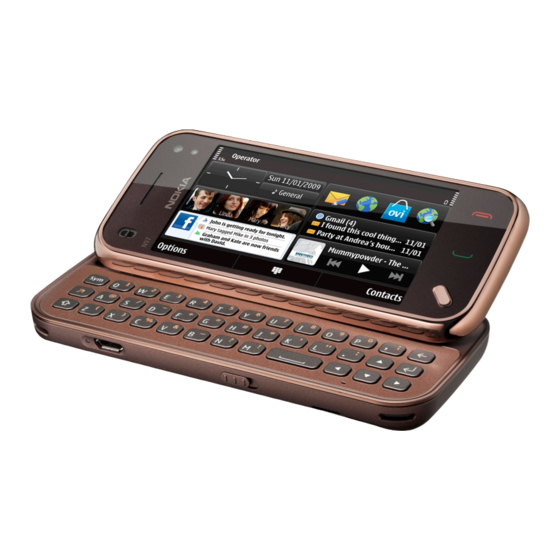
Table 3 Data ................................. 1–11 Table 4 Messaging ............................... 1–11 Table 5 Positioning ............................. 1–11 Table 6 Power ..............................1–12 List of Figures Figure 1 View of RM-555............................1–5 Issue 1 COMPANY CONFIDENTIAL Page 1 –3 Copyright © 2009 Nokia. All rights reserved. - Page 14 RM-555 General Information (This page left intentionally blank.) Page 1 –4 COMPANY CONFIDENTIAL Issue 1 Copyright © 2009 Nokia. All rights reserved.
-
Page 15: Product Selection
RM-555 General Information Product selection RM-555 is a GSM/HSDPA/WCDMA tri-mode handportable multimedia computer with a person centric touch UI, integrated GPS (A-GPS OMA SUPL) and WLAN. It supports EGSM 850/900/1800/1900 and WCDMA 900/1900/2100 bands, and CSD/HSCSD, GPRS/EGPRS, WCDMA/HSDPA data bearers. - Page 16 • 3.2” nHD (640 x 360 pixels) colour display (active area 39.6 mm x 70.4 mm), up to 16M colors, 16:9 aspect ratio • Digital Ambient Light Sensor (ALS) – used to optimize display/key brightness and power consumption • Slideshow from Gallery Page 1 –6 COMPANY CONFIDENTIAL Issue 1 Copyright © 2009 Nokia. All rights reserved.
- Page 17 • Nokia XpressPrint – direct printing via USB (PictBridge), Bluetooth (BPP), and WLAN (UPnP), from memory card or via online printing Store • 8GB internal user memory • Nokia XpressTransfer – easy to transfer and organize photos and video between your device and a compatible PC • Nokia Lifeblog (mobile & PC) Music •...
- Page 18 • MicroSD memory card - support up to 16GB • Nokia 3.5 mm AV connector Add-on software framework • Symbian 9.4 OS • Nokia Series 60, 5th edition, feature pack 2 • Java: MIDP2.0 • C++ and Java SDKs Additional technical specifications •...
-
Page 19: Mobile Enhancements
Mobile enhancements Table 1 Audio Enhancement Type Music headset WH-701 Mini speakers MD-6 MD-8 Hearing aids HDA-12 LPS-5 Wired headsets WH-102 WH-205 WH-500 WH-700 WH-701 WH-800 WH-900 Issue 1 COMPANY CONFIDENTIAL Page 1 –9 Copyright © 2009 Nokia. All rights reserved. - Page 20 BH-214 BH-215 BH-216 BH-301 BH-501 BH-504 BH-600 BH-602 BH-604 BH-606 BH-607 BH-700 BH-701 BH-703 BH-704 BH-803 BH-804 BH-900 BH-902 BH-903 BH-904 BH-905 Bluetooth speakers MD-5W MD-7W Page 1 –10 COMPANY CONFIDENTIAL Issue 1 Copyright © 2009 Nokia. All rights reserved.
-
Page 21: Table 2 Car
MU-43, 8 GB MU-44 16 GB Table 4 Messaging Enhancement Type Other multimedia peripherals SU-33W Stylus STYLUS PEN ASSY Table 5 Positioning Enhancement Type Home connectivity AD-xx HD-1 Issue 1 COMPANY CONFIDENTIAL Page 1 –11 Copyright © 2009 Nokia. All rights reserved. -
Page 22: Technical Specifications
GSM1800: 1710 - 1785 MHz GSM1900: 1850 - 1910 MHz WCDMA VIII (900): 880 - 915 MHz WCDMA II (1900): 1850-1910MHz WCDMA I (2100): 1920 - 1980 MHz Page 1 –12 COMPANY CONFIDENTIAL Issue 1 Copyright © 2009 Nokia. All rights reserved. -
Page 23: Battery Endurance
WCDMA I (2100): 75 Battery endurance Battery Capacity (mAh) BL-4D 1200 Please note that the observed values below should be used only as an unqualified reference. Issue 1 COMPANY CONFIDENTIAL Page 1 –13 Copyright © 2009 Nokia. All rights reserved. -
Page 24: Environmental Conditions
Therefore the phone heat which is created by the phone function, eg: voice call, video recording etc, can shut down itself although the ambient temperature is under 55 Page 1 –14 COMPANY CONFIDENTIAL Issue 1 Copyright © 2009 Nokia. All rights reserved. - Page 25 Condensed or dripping water may cause intermittent malfunctions. Protection against dripping water has to be implemented in (enclosure) mechanics. Continuous dampness will cause permanent damage to the module. Issue 1 COMPANY CONFIDENTIAL Page 1 –15 Copyright © 2009 Nokia. All rights reserved.
- Page 26 RM-555 General Information (This page left intentionally blank.) Page 1 –16 COMPANY CONFIDENTIAL Issue 1 Copyright © 2009 Nokia. All rights reserved.
-
Page 27: Issue 1 Company Confidential Page
Nokia Customer Care 2 — Service Tools and Service Concepts Issue 1 COMPANY CONFIDENTIAL Page 2 –1 Copyright © 2009 Nokia. All rights reserved. - Page 28 RM-555 Service Tools and Service Concepts (This page left intentionally blank.) Page 2 –2 COMPANY CONFIDENTIAL Issue 1 Copyright © 2009 Nokia. All rights reserved.
-
Page 29: Table Of Contents
Figure 12 Service concept for RF testing and RF/BB tuning ................2–20 Figure 13 WLAN functionality testing concept with SB-7 ................2–21 Figure 14 Service concept for RF testing and RF/BB tuning ................2–22 Issue 1 COMPANY CONFIDENTIAL Page 2 –3 Copyright © 2009 Nokia. All rights reserved. - Page 30 Figure 21 Use 2 phone screws from the top side of the UI module............... 2–27 Figure 22 Use 1 phone screw from the bottom side of the Module Jig ............2–28 Page 2 –4 COMPANY CONFIDENTIAL Issue 1 Copyright © 2009 Nokia. All rights reserved.
-
Page 31: Service Tools
The table below gives a short overview of service devices that can be used for testing, error analysis, and repair of product RM-555. For the correct use of the service devices, and the best effort of workbench setup, please refer to various concepts. - Page 32 • Provides galvanic connection to all needed test pads in module • Multiplexing between USB and FBUS media, controlled by Vusb • Connector for control unit • Access for Audio-, MMC, and USB connectors • Module jig attenuation values for RM-555: Band Attenuation GSM850 TX 824-849 0.2dB...
-
Page 33: Cables
The table below gives a short overview of service devices that can be used for testing, error analysis, and repair of product RM-555. For the correct use of the service devices, and the best effort of workbench setup, please refer to various concepts. - Page 34 FPS-21 sales package. CA-35S Power cable CA-35S is a power cable for connecting, for example, the FPS-21 flash prommer to the Point-Of-Sales (POS) flash adapter. Page 2 –8 COMPANY CONFIDENTIAL Issue 1 Copyright © 2009 Nokia. All rights reserved.
-
Page 35: Service Concepts
Service concepts POS (Point of Sale) flash concept Figure 2 POS flash concept Type Description Product specific tools Issue 1 COMPANY CONFIDENTIAL Page 2 –9 Copyright © 2009 Nokia. All rights reserved. -
Page 36: Table 6 Power
Figure 3 Basic flash concept with FPS-21 Type Description Product specific devices FS-125 Flash adapter Other devices FPS-21 Flash prommer box AC-35 Power supply PK-1 SW security device Page 2 –10 COMPANY CONFIDENTIAL Issue 1 Copyright © 2009 Nokia. All rights reserved. - Page 37 Figure 4 CU-4 flash concept with FPS-21 Type Description Product specific devices FS-125 Flash adapter Other devices CU-4 Control unit FPS-21 Flash prommer box AC-35 Power supply PK-1 SW security device Issue 1 COMPANY CONFIDENTIAL Page 2 –11 Copyright © 2009 Nokia. All rights reserved.
-
Page 38: Flash Concept With Fps-21 And Sb-6............................................................................................................. Flash Concept With Ss-46 And Ca-89Ds
Standard USB cable USB cable Flash concept with FPS-21 and SB-6 Figure 5 Flash concept with FPS-21 and SB-6 Type Description Product specific tools FS-125 Flash adapter Page 2 –12 COMPANY CONFIDENTIAL Issue 1 Copyright © 2009 Nokia. All rights reserved. - Page 39 PC with Phoenix service software Cables XCS-4 Modular cable CA-35S Power cable USB cable Flash concept with SS-46 and CA-89DS Figure 6 Flash concept with SS-46 and CA-89DS Issue 1 COMPANY CONFIDENTIAL Page 2 –13 Copyright © 2009 Nokia. All rights reserved.
-
Page 40: Flash Concept With Ss-62 And Ca-89Ds
PC with Phoenix service software Cables CA-89DS Cable Flash concept with SS-62 and CA-89DS Figure 7 Flash concept with SS-62 and CA-89DS Type Description Product specific tools FS-125 Flash adapter Page 2 –14 COMPANY CONFIDENTIAL Issue 1 Copyright © 2009 Nokia. All rights reserved. -
Page 41: Flash Concept With Fps-21, Ss-62 And
Flash concept with FPS-21, SS-62 and SB-6 Figure 8 Flash concept with FPS-21, SS-62 and SB-6 Type Description Product specific tools FS-125 Flash adapter Other tools Issue 1 COMPANY CONFIDENTIAL Page 2 –15 Copyright © 2009 Nokia. All rights reserved. -
Page 42: Flash Concept With Fps-21, Ss-62 And
Flash concept with FPS-21, SS-62 and SB-7 Figure 9 Flash concept with FPS-21, SB-7 and JBT-9 Type Description Product specific tools FS-125 Flash adapter Other tools Page 2 –16 COMPANY CONFIDENTIAL Issue 1 Copyright © 2009 Nokia. All rights reserved. -
Page 43: Module Jig Service Concept
Power cable USB cable Module jig service concept Figure 10 Module jig service concept Type Description Phone specific devices MJ-243 Module jig Other devices CU-4 Control unit Issue 1 COMPANY CONFIDENTIAL Page 2 –17 Copyright © 2009 Nokia. All rights reserved. -
Page 44: Module Jig Service Concept With
XRS-6 RF cable CA-158RS BT/WLAN tuning cable USB cable GPIB control cable Module jig service concept with SB-6 Figure 11 Module jig service concept with SB-6 Page 2 –18 COMPANY CONFIDENTIAL Issue 1 Copyright © 2009 Nokia. All rights reserved. - Page 45 Smart card Measurement equipment PC with Phoenix service software Cables PCS-1 DC power cable XRS-6 RF cable CA-158RS BT/WLAN tuning cable GPIB control cable USB cable Issue 1 COMPANY CONFIDENTIAL Page 2 –19 Copyright © 2009 Nokia. All rights reserved.
-
Page 46: Service Concept For Rf Testing And Rf/Bb Tuning
Smart card reader PC with Phoenix service software Cables DAU-9S MBUS cable PCS-1 DC power cable XRS-6 RF cable CA-158RS BT/WLAN tuning cable GPIB control cable Page 2 –20 COMPANY CONFIDENTIAL Issue 1 Copyright © 2009 Nokia. All rights reserved. -
Page 47: Wlan Functionality Testing Concept With Sb-7
Other tools CU-4 Control unit PCS-1 DC power cable PK-1 SW Security device SS-62 Generic base adapter Cables PCS-1 Power cable DAU-9S Cable Standard USB cable Issue 1 COMPANY CONFIDENTIAL Page 2 –21 Copyright © 2009 Nokia. All rights reserved. -
Page 48: Bluetooth Testing Concept With
Smart card SB-6 Bluetooth test and interface box Smart card reader PC with Phoenix service software Cables DAU-9S MBUS cable PCS-1 DC power cable USB cable Page 2 –22 COMPANY CONFIDENTIAL Issue 1 Copyright © 2009 Nokia. All rights reserved. -
Page 49: Gps Testing Concept With Gps Rf Coupler
Flash adapter base Smart card reader Measurement equipment PC with Phoenix service software Cables CA-58RS RF service cable (product-specific adapter cable) PCS-1 Power cable DAU-9S MBUS cable Issue 1 COMPANY CONFIDENTIAL Page 2 –23 Copyright © 2009 Nokia. All rights reserved. -
Page 50: Module Jig Mj-243 Set-Up Instruction
Service Tools and Service Concepts Type Description XRS-6 RF cable 20dB attenuator Interface cable USB cable Module jig MJ-243 set-up instruction Figure 16 Module jig block diagram Page 2 –24 COMPANY CONFIDENTIAL Issue 1 Copyright © 2009 Nokia. All rights reserved. - Page 51 RM-555 Service Tools and Service Concepts Figure 17 Module jig top view (without module setup) Figure 18 Module jig top view (with module setup) Issue 1 COMPANY CONFIDENTIAL Page 2 –25 Copyright © 2009 Nokia. All rights reserved.
- Page 52 3 Remove the keymat from the UI carefully. Try not to bend the keymat if possible. 4 Optionally, SP6 can be disassembled in order to fix the UI module to it easily. Page 2 –26 COMPANY CONFIDENTIAL Issue 1 Copyright © 2009 Nokia. All rights reserved.
- Page 53 8 Attach a keymat to the UI module. Figure 20 Connecting the UI module to SP6 Flex connectors Figure 21 Use 2 phone screws from the top side of the UI module Issue 1 COMPANY CONFIDENTIAL Page 2 –27 Copyright © 2009 Nokia. All rights reserved.
-
Page 54: Touch Panel Recalibration
Figure 22 Use 1 phone screw from the bottom side of the Module Jig Touch panel recalibration General After replacing the RM-555 A-Cover, the touch panel settings in the phone must be recalibrated to match with the new touch panel. To perform this procedure, you will require the following equipment: •... -
Page 55: Recalibration Procedure
10 Start the calibration. Recalibration procedure 1 Touch the center of the “+” points on the Phone UI in the correct order (1, 2, 3) using the SS-93 Tool. Issue 1 COMPANY CONFIDENTIAL Page 2 –29 Copyright © 2009 Nokia. All rights reserved. - Page 56 RM-555 Service Tools and Service Concepts Tip: After touching each point on the phone UI, check that the touch was registered properly on the Phoenix screen. Page 2 –30 COMPANY CONFIDENTIAL Issue 1 Copyright © 2009 Nokia. All rights reserved.
-
Page 57: Troubleshooting
• Lines can be drawn to the edges (within 1-2 mm) of the screen. Troubleshooting When touching the points on the phone UI, there is a 30-second timeout. If this expires without receiving 3 points, the procedure will abort. Issue 1 COMPANY CONFIDENTIAL Page 2 –31 Copyright © 2009 Nokia. All rights reserved. - Page 58 • Drawn lines are not following the tip of the SS-93/stylus • There are large “dead” areas where lines cannot be drawn If verification continues to fail, contact your next level of support. Page 2 –32 COMPANY CONFIDENTIAL Issue 1 Copyright © 2009 Nokia. All rights reserved.
- Page 59 Nokia Customer Care 3 — BB Troubleshooting and Manual Tuning Guide Issue 1 COMPANY CONFIDENTIAL Page 3 –1 Copyright © 2009 Nokia. All rights reserved.
- Page 60 RM-555 BB Troubleshooting and Manual Tuning Guide (This page left intentionally blank.) Page 3 –2 COMPANY CONFIDENTIAL Issue 1 Copyright © 2009 Nokia. All rights reserved.
- Page 61 3–64 WLAN auto tuning ............................3–67 Bluetooth and FM radio ............................3–69 Bluetooth and FM radio introduction......................3–69 Bluetooth and FM radio component placement ..................3–70 Issue 1 COMPANY CONFIDENTIAL Page 3 –3 Copyright © 2009 Nokia. All rights reserved.
- Page 62 Figure 43 WLAN component placement......................3–62 Figure 44 WLAN auto tune settings........................3–68 Figure 45 WLAN autotuning results ........................3–69 Figure 46 Key component placement for BTHFMRDS2.3M................3–71 Page 3 –4 COMPANY CONFIDENTIAL Issue 1 Copyright © 2009 Nokia. All rights reserved.
- Page 63 Figure 50 Single-ended output waveform of the AV Mic to AV Ear loop............3–78 Figure 51 Single-ended output waveform of the HP Mic to AV Ear loop............3–78 Issue 1 COMPANY CONFIDENTIAL Page 3 –5 Copyright © 2009 Nokia. All rights reserved.
- Page 64 RM-555 BB Troubleshooting and Manual Tuning Guide (This page left intentionally blank.) Page 3 –6 COMPANY CONFIDENTIAL Issue 1 Copyright © 2009 Nokia. All rights reserved.
-
Page 65: Baseband Main Troubleshooting
RM-555 BB Troubleshooting and Manual Tuning Guide Baseband main troubleshooting Troubleshooting flow Issue 1 COMPANY CONFIDENTIAL Page 3 –7 Copyright © 2009 Nokia. All rights reserved. - Page 66 RM-555 BB Troubleshooting and Manual Tuning Guide Page 3 –8 COMPANY CONFIDENTIAL Issue 1 Copyright © 2009 Nokia. All rights reserved.
- Page 67 RM-555 BB Troubleshooting and Manual Tuning Guide Issue 1 COMPANY CONFIDENTIAL Page 3 –9 Copyright © 2009 Nokia. All rights reserved.
-
Page 68: Dead Or Jammed Device Troubleshooting
RM-555 BB Troubleshooting and Manual Tuning Guide Dead or jammed device troubleshooting Troubleshooting flow Page 3 –10 COMPANY CONFIDENTIAL Issue 1 Copyright © 2009 Nokia. All rights reserved. -
Page 69: General Power Checking
LP5952 Camera HWA VCAM_1V8 core VCAM_2V8 BH28SA2 Cameras VBAT VCORE TPS62350 Rapido core VBAT FAN5355 TPS62600 VIO, VDRAM VBAT FAN5361 MicroSD card VBAT levelsifter when used Issue 1 COMPANY CONFIDENTIAL Page 3 –11 Copyright © 2009 Nokia. All rights reserved. - Page 70 MENU_LED VBAT FLASH_LE AS3645A/ 6.68 Camera flash VBAT LM3555 Indicator_ AS3645A/ Video indicator VBAT LED+ LM3555 VCORE_eM BH30SA2 eMMC core VBAT VIO_eMMC BH18SA2 eMMC IO VBAT Page 3 –12 COMPANY CONFIDENTIAL Issue 1 Copyright © 2009 Nokia. All rights reserved.
-
Page 71: Clocking Troubleshooting
RM-555 BB Troubleshooting and Manual Tuning Guide Clocking troubleshooting Troubleshooting flow Issue 1 COMPANY CONFIDENTIAL Page 3 –13 Copyright © 2009 Nokia. All rights reserved. -
Page 72: Usb Charging Troubleshooting
RM-555 BB Troubleshooting and Manual Tuning Guide USB charging troubleshooting Troubleshooting flow Page 3 –14 COMPANY CONFIDENTIAL Issue 1 Copyright © 2009 Nokia. All rights reserved. -
Page 73: Backup Battery Troubleshooting
Switch off the phone, disconnect the main battery and monitor that the voltage of the backup battery decreases. Normal behaviour of the voltage is described in the figures below: Issue 1 COMPANY CONFIDENTIAL Page 3 –15 Copyright © 2009 Nokia. All rights reserved. - Page 74 G2200 if necessary. If the voltage stays ~0V, check resistance VBACK against GND. If there is no shortcircuit, AVILMA N2200 is faulty. Replace N2200. Page 3 –16 COMPANY CONFIDENTIAL Issue 1 Copyright © 2009 Nokia. All rights reserved.
-
Page 75: Flash Programming Troubleshooting
RM-555 BB Troubleshooting and Manual Tuning Guide Flash programming troubleshooting Troubleshooting flow Issue 1 COMPANY CONFIDENTIAL Page 3 –17 Copyright © 2009 Nokia. All rights reserved. - Page 76 RM-555 BB Troubleshooting and Manual Tuning Guide Page 3 –18 COMPANY CONFIDENTIAL Issue 1 Copyright © 2009 Nokia. All rights reserved.
- Page 77 RM-555 BB Troubleshooting and Manual Tuning Guide Issue 1 COMPANY CONFIDENTIAL Page 3 –19 Copyright © 2009 Nokia. All rights reserved.
-
Page 78: Combo Memory Troubleshooting
RM-555 BB Troubleshooting and Manual Tuning Guide Combo memory troubleshooting Troubleshooting flow Page 3 –20 COMPANY CONFIDENTIAL Issue 1 Copyright © 2009 Nokia. All rights reserved. -
Page 79: Microsd Card Troubleshooting
RM-555 BB Troubleshooting and Manual Tuning Guide MicroSD card troubleshooting Troubleshooting flow Issue 1 COMPANY CONFIDENTIAL Page 3 –21 Copyright © 2009 Nokia. All rights reserved. - Page 80 RM-555 BB Troubleshooting and Manual Tuning Guide Page 3 –22 COMPANY CONFIDENTIAL Issue 1 Copyright © 2009 Nokia. All rights reserved.
-
Page 81: Usb Troubleshooting
RM-555 BB Troubleshooting and Manual Tuning Guide USB troubleshooting Troubleshooting flow Issue 1 COMPANY CONFIDENTIAL Page 3 –23 Copyright © 2009 Nokia. All rights reserved. -
Page 82: Sim Card Troubleshooting
RM-555 BB Troubleshooting and Manual Tuning Guide SIM card troubleshooting Troubleshooting flow Page 3 –24 COMPANY CONFIDENTIAL Issue 1 Copyright © 2009 Nokia. All rights reserved. - Page 83 RM-555 BB Troubleshooting and Manual Tuning Guide Issue 1 COMPANY CONFIDENTIAL Page 3 –25 Copyright © 2009 Nokia. All rights reserved.
-
Page 84: Power Key Troubleshooting
RM-555 BB Troubleshooting and Manual Tuning Guide Power key troubleshooting Troubleshooting flow Page 3 –26 COMPANY CONFIDENTIAL Issue 1 Copyright © 2009 Nokia. All rights reserved. -
Page 85: Vibra Troubleshooting
RM-555 BB Troubleshooting and Manual Tuning Guide Vibra troubleshooting Troubleshooting flow Issue 1 COMPANY CONFIDENTIAL Page 3 –27 Copyright © 2009 Nokia. All rights reserved. -
Page 86: Hall Sensor Troubleshooting
The hall sensor system is comprised of a hall sensor in the lower part of the phone and a magnet in the upper sliding/pivoting part of the phone. Page 3 –28 COMPANY CONFIDENTIAL Issue 1 Copyright © 2009 Nokia. All rights reserved. - Page 87 RM-555 BB Troubleshooting and Manual Tuning Guide Troubleshooting flow Issue 1 COMPANY CONFIDENTIAL Page 3 –29 Copyright © 2009 Nokia. All rights reserved.
-
Page 88: Magnetometer Troubleshooting
Magnetizeable metals and magnetic items should be kept more than 20 cm away from the phone, and the phone should be kept stable, during testing. Otherwise the self test and/or functionality will be affected. Troubleshooting flow Page 3 –30 COMPANY CONFIDENTIAL Issue 1 Copyright © 2009 Nokia. All rights reserved. -
Page 89: Accelerometer Troubleshooting
There is a boot between the sensor and the touch window, which isolates the IR transmitter from the IR receiver by preventing the reflection from the touch window surface. Issue 1 COMPANY CONFIDENTIAL Page 3 –31 Copyright © 2009 Nokia. All rights reserved. -
Page 90: Proximity Sensor Troubleshooting
If the automatic flow does not provide enough information, a manual check can be done to narrow down the cause of the fault. Page 3 –32 COMPANY CONFIDENTIAL Issue 1 Copyright © 2009 Nokia. All rights reserved. - Page 91 RM-555 BB Troubleshooting and Manual Tuning Guide Troubleshooting flow Issue 1 COMPANY CONFIDENTIAL Page 3 –33 Copyright © 2009 Nokia. All rights reserved.
- Page 92 RM-555 BB Troubleshooting and Manual Tuning Guide Troubleshooting flow Page 3 –34 COMPANY CONFIDENTIAL Issue 1 Copyright © 2009 Nokia. All rights reserved.
-
Page 93: Proxy Boot Replacement Process Instructions
RM-555 BB Troubleshooting and Manual Tuning Guide Proxy boot replacement process instructions Assembly/Disassembly of boot Figure 23 Assembly/Disassebly of boot Issue 1 COMPANY CONFIDENTIAL Page 3 –35 Copyright © 2009 Nokia. All rights reserved. - Page 94 BB Troubleshooting and Manual Tuning Guide Proxy boot replacement Figure 24 Remove original proxy boot Figure 25 Blow under side of new boot and top of sensor Page 3 –36 COMPANY CONFIDENTIAL Issue 1 Copyright © 2009 Nokia. All rights reserved.
- Page 95 RM-555 BB Troubleshooting and Manual Tuning Guide Figure 26 Assemble new boot Figure 27 Blow and check assembly condition Issue 1 COMPANY CONFIDENTIAL Page 3 –37 Copyright © 2009 Nokia. All rights reserved.
- Page 96 RM-555 BB Troubleshooting and Manual Tuning Guide Check point (z-dir) Figure 28 Proxy boot check point Figure 29 Boot floating now allowed Page 3 –38 COMPANY CONFIDENTIAL Issue 1 Copyright © 2009 Nokia. All rights reserved.
-
Page 97: Resistive Touch Screen Troubleshooting
RM-555 BB Troubleshooting and Manual Tuning Guide Resistive touch screen troubleshooting Resistive touch screen page 1(2) Issue 1 COMPANY CONFIDENTIAL Page 3 –39 Copyright © 2009 Nokia. All rights reserved. - Page 98 RM-555 BB Troubleshooting and Manual Tuning Guide Resistive touch screen page 2(2) Page 3 –40 COMPANY CONFIDENTIAL Issue 1 Copyright © 2009 Nokia. All rights reserved.
- Page 99 RM-555 BB Troubleshooting and Manual Tuning Guide Touch controller basic checks Issue 1 COMPANY CONFIDENTIAL Page 3 –41 Copyright © 2009 Nokia. All rights reserved.
-
Page 100: Hardware Keys Troubleshooting
RM-555 BB Troubleshooting and Manual Tuning Guide Touch screen basic checks Hardware keys troubleshooting Context There are two possible failure modes in the keyboard module: Page 3 –42 COMPANY CONFIDENTIAL Issue 1 Copyright © 2009 Nokia. All rights reserved. -
Page 101: Display Module Troubleshooting
Figure 30 Keymatrix Display module troubleshooting General instructions for display troubleshooting Context • The display is in a normal mode when the phone is in active use. Issue 1 COMPANY CONFIDENTIAL Page 3 –43 Copyright © 2009 Nokia. All rights reserved. - Page 102 Phoenix service software. ii Start iii Read the phone information to check that the engine is functioning normally (you should be able to read the Phone ID). Page 3 –44 COMPANY CONFIDENTIAL Issue 1 Copyright © 2009 Nokia. All rights reserved.
-
Page 103: Display Troubleshooting
Before going to display troubleshooting flow, make sure that the engine is working and starting up correctly. If the problem is in the engine, go to baseband troubleshooting. Issue 1 COMPANY CONFIDENTIAL Page 3 –45 Copyright © 2009 Nokia. All rights reserved. - Page 104 RM-555 BB Troubleshooting and Manual Tuning Guide Troubleshooting flow Page 3 –46 COMPANY CONFIDENTIAL Issue 1 Copyright © 2009 Nokia. All rights reserved.
-
Page 105: Display Backlights Troubleshooting
Display backlights troubleshooting Context The device has a dedicated display WLED driver whose intensity is controlled by Display itself by CABC (content adaptive backlight control) signal. Issue 1 COMPANY CONFIDENTIAL Page 3 –47 Copyright © 2009 Nokia. All rights reserved. - Page 106 RM-555 BB Troubleshooting and Manual Tuning Guide Troubleshooting flow Page 3 –48 COMPANY CONFIDENTIAL Issue 1 Copyright © 2009 Nokia. All rights reserved.
-
Page 107: Led And Led Driver Troubleshooting
. Brightness of backlights can be adjusted manually, and it affects the keypad. Keyboard backlights and some LEDs can be turned ON/OFF separately but not without switching on the display lights. Issue 1 COMPANY CONFIDENTIAL Page 3 –49 Copyright © 2009 Nokia. All rights reserved. - Page 108 RM-555 BB Troubleshooting and Manual Tuning Guide Troubleshooting flow Page 3 –50 COMPANY CONFIDENTIAL Issue 1 Copyright © 2009 Nokia. All rights reserved.
-
Page 109: Ambient Light Sensor Troubleshooting
GPS signal is routed to the antenna feed point through a diplexer. The GPS/WLAN/Bluetooth antenna has 2 contacts on the PWB with C-clips. Figure 31 GPS/WLAN/Bluetooth antenna Figure 32 GPS/WLAN/Bluetooth antenna assembled on B-cover Issue 1 COMPANY CONFIDENTIAL Page 3 –51 Copyright © 2009 Nokia. All rights reserved. -
Page 110: Gps Layout And Basic Test Points
RM-555 BB Troubleshooting and Manual Tuning Guide Figure 33 Two C-clips on PWB GPS layout and basic test points Page 3 –52 COMPANY CONFIDENTIAL Issue 1 Copyright © 2009 Nokia. All rights reserved. -
Page 111: Gps Rf Test Points
GPS signals are available on the test points listed below: • U2Tx (J6200, activity on this pin indicates the GPS is operating) GPS RF test points Figure 35 GPS test points Issue 1 COMPANY CONFIDENTIAL Page 3 –53 Copyright © 2009 Nokia. All rights reserved. -
Page 112: Gps Settings For Phoenix
On will turn on all the RF sections of the ASIC and so all LDOs will be present. Turning Receiver Action Note: These checks are part of GPS basic checks troubleshooting (page 3–60) Figure 36 GPS Control dialog box Page 3 –54 COMPANY CONFIDENTIAL Issue 1 Copyright © 2009 Nokia. All rights reserved. -
Page 113: Oscillator Test
Rx Control window, go to the Simple Tests section, select Oscillator Test and click Start. The Offset In the result will be returned and should be within the limits of +- 84Hz. Issue 1 COMPANY CONFIDENTIAL Page 3 –55 Copyright © 2009 Nokia. All rights reserved. -
Page 114: Receiver Self Test
Oscillator test to prolong and result in Phoenix timing out. If you are carrying out both of these tests, run the Oscillator Test first, after which you can run the Receiver Self Test. Page 3 –56 COMPANY CONFIDENTIAL Issue 1 Copyright © 2009 Nokia. All rights reserved. -
Page 115: Cw Test
MHz tone at the GPS test pad J6201 at a level of -110dBm and click Start. For Pin = -110dBm and negligible other losses, the expected result ranges are: • Galvanic 29.8dB to 38.1dB • Radiated 25.8dB to 38.1dB Issue 1 COMPANY CONFIDENTIAL Page 3 –57 Copyright © 2009 Nokia. All rights reserved. -
Page 116: Quick Test Window
Oscillator Test . It does not necessarily mean that Oscillator Test has failed, but carrying out the Oscillator Test (page 3–55), Receiver Self Test (page 3–56) CW Test (page 3–57) individually will give more valid results. Page 3 –58 COMPANY CONFIDENTIAL Issue 1 Copyright © 2009 Nokia. All rights reserved. -
Page 117: Gps Failure Troubleshooting
GPS troubleshooting is broken down into two parts: General GPS failure & GPS basic checks. The GPS failure troubleshooting flow can be followed and, where applicable, will feed into the basic checks troubleshooting flow. Issue 1 COMPANY CONFIDENTIAL Page 3 –59 Copyright © 2009 Nokia. All rights reserved. - Page 118 RM-555 BB Troubleshooting and Manual Tuning Guide Troubleshooting flow Page 3 –60 COMPANY CONFIDENTIAL Issue 1 Copyright © 2009 Nokia. All rights reserved.
-
Page 119: Gps Basic Checks Troubleshooting
RM-555 BB Troubleshooting and Manual Tuning Guide GPS basic checks troubleshooting Troubleshooting flow Issue 1 COMPANY CONFIDENTIAL Page 3 –61 Copyright © 2009 Nokia. All rights reserved. -
Page 120: Wlan Troubleshooting
SPI interface. BT and WLAN use 38.4MHz clock from Vapaus (N7500) with the clock buffer (D6003). Figure 42 WLAN circuitry WLAN component placement Figure 43 WLAN component placement WLAN settings for Phoenix Use the following to test WLAN using Phoenix: Page 3 –62 COMPANY CONFIDENTIAL Issue 1 Copyright © 2009 Nokia. All rights reserved. - Page 121 This test verifies that the WLAN to BTH co-existence interface signals are properly connected and there are no open circuit or shorts on the four interface signals. The co-existence interface comprises BTH Txconfig, BTH RF Active, BTH Priority, and BTH Frequency. Issue 1 COMPANY CONFIDENTIAL Page 3 –63 Copyright © 2009 Nokia. All rights reserved.
-
Page 122: Wlan Functional Tests
The difference between the currents in (1) and (2) should be between 190 to 220mA. When WLAN is ON, the firmware has been downloaded and the WLAN module is in the receive state. When OFF WLAN is powered down. Page 3 –64 COMPANY CONFIDENTIAL Issue 1 Copyright © 2009 Nokia. All rights reserved. - Page 123 2 To finish the test select the Finish option button. The difference between the two readings should be approximately 150mA and measures the transmit current in 11MBPS, 802.11b mode of operation. Issue 1 COMPANY CONFIDENTIAL Page 3 –65 Copyright © 2009 Nokia. All rights reserved.
- Page 124 WLAN network. Simply starting an Rx test will show the number of packets detected by the WLAN module as it monitors the network. However, it does require a properly configured WLAN network. Page 3 –66 COMPANY CONFIDENTIAL Issue 1 Copyright © 2009 Nokia. All rights reserved.
-
Page 125: Wlan Auto Tuning
RF cable. Start Phoenix WLAN autotune window. Check the settings and verify your PC communicates with CMU200 via GPIB. Auto tuning procedure 1 Start tuning by pressing Tune. Issue 1 COMPANY CONFIDENTIAL Page 3 –67 Copyright © 2009 Nokia. All rights reserved. - Page 126 RM-555 BB Troubleshooting and Manual Tuning Guide Figure 44 WLAN auto tune settings Page 3 –68 COMPANY CONFIDENTIAL Issue 1 Copyright © 2009 Nokia. All rights reserved.
-
Page 127: Bluetooth And Fm Radio
Open circuit solder joints or Replacement of Bluetooth/FM ASIC/ Bluetooth on phone component failure of BTH/ module. user interface. FM ASIC/module BB ASICs or SMD components. Issue 1 COMPANY CONFIDENTIAL Page 3 –69 Copyright © 2009 Nokia. All rights reserved. -
Page 128: Bluetooth And Fm Radio Component Placement
FM audio through headset. Bluetooth and FM radio component placement The figures below show the key component placement for BTHFMRDS2.3M. Page 3 –70 COMPANY CONFIDENTIAL Issue 1 Copyright © 2009 Nokia. All rights reserved. -
Page 129: Bluetooth And Fm Radio Self Tests
1. Place the phone in the flash adapter. 2. Start Phoenix service software. 3. Choose File → Scan Product. 4. From the Mode drop-down menu, set to Local. Issue 1 COMPANY CONFIDENTIAL Page 3 –71 Copyright © 2009 Nokia. All rights reserved. -
Page 130: Bluetooth Ber Test
5. Locate the BT-box serial number (12 digits) found in the type label on the back of the JBT-3, JBT-6, JBT-9, or SB-6 Bluetooth test box. 6. In the Bluetooth LOCALS window, write the 12-digit serial number on the Counterpart BT Device Address line. Page 3 –72 COMPANY CONFIDENTIAL Issue 1 Copyright © 2009 Nokia. All rights reserved. - Page 131 RM-555 BB Troubleshooting and Manual Tuning Guide 7. Place the BT-box near (within 10 cm) of the phone and click Run BER Test. Issue 1 COMPANY CONFIDENTIAL Page 3 –73 Copyright © 2009 Nokia. All rights reserved.
-
Page 132: Bluetooth And Fm Radio Module Troubleshooting
RM-555 BB Troubleshooting and Manual Tuning Guide Bluetooth and FM radio module troubleshooting Troubleshooting flow Page 3 –74 COMPANY CONFIDENTIAL Issue 1 Copyright © 2009 Nokia. All rights reserved. -
Page 133: Tv Out Troubleshooting
Single-ended external earpiece and differential internal earpiece outputs can be measured either with a single-ended or a differential probe. When measuring with a single-ended probe each output is measured against the ground. Issue 1 COMPANY CONFIDENTIAL Page 3 –75 Copyright © 2009 Nokia. All rights reserved. - Page 134 [mVp-p] (fixed) AV Mic to AV HS_MIC & HS_EAR_L & Earpiece HS_EAR_R & AV Mic to HP HS_MIC & EarP & GND Earpiece EarN & GND Page 3 –76 COMPANY CONFIDENTIAL Issue 1 Copyright © 2009 Nokia. All rights reserved.
- Page 135 Figure 49 Single-ended output waveform of the Ext_microphone in Int handsfree out loop measurement when speaker is connected (measured at speaker pads). No filter is used. External output from AV Issue 1 COMPANY CONFIDENTIAL Page 3 –77 Copyright © 2009 Nokia. All rights reserved.
- Page 136 Figure 50 Single-ended output waveform of the AV Mic to AV Ear loop. External output from AV (acoustic input) Figure 51 Single-ended output waveform of the HP Mic to AV Ear loop. Page 3 –78 COMPANY CONFIDENTIAL Issue 1 Copyright © 2009 Nokia. All rights reserved.
-
Page 137: Internal Earpiece Troubleshooting
RM-555 BB Troubleshooting and Manual Tuning Guide Internal earpiece troubleshooting Troubleshooting flow Issue 1 COMPANY CONFIDENTIAL Page 3 –79 Copyright © 2009 Nokia. All rights reserved. -
Page 138: Internal Microphone Troubleshooting
RM-555 BB Troubleshooting and Manual Tuning Guide Internal microphone troubleshooting Troubleshooting flow Page 3 –80 COMPANY CONFIDENTIAL Issue 1 Copyright © 2009 Nokia. All rights reserved. -
Page 139: Internal Handsfree Speaker Troubleshooting
RM-555 BB Troubleshooting and Manual Tuning Guide Internal handsfree speaker troubleshooting Troubleshooting flow Issue 1 COMPANY CONFIDENTIAL Page 3 –81 Copyright © 2009 Nokia. All rights reserved. -
Page 140: External Microphone Troubleshooting
RM-555 BB Troubleshooting and Manual Tuning Guide External microphone troubleshooting Troubleshooting flow Page 3 –82 COMPANY CONFIDENTIAL Issue 1 Copyright © 2009 Nokia. All rights reserved. -
Page 141: External Headset Earpiece Troubleshooting
RM-555 BB Troubleshooting and Manual Tuning Guide External headset earpiece troubleshooting Troubleshooting flow Issue 1 COMPANY CONFIDENTIAL Page 3 –83 Copyright © 2009 Nokia. All rights reserved. -
Page 142: Acoustics Troubleshooting
The phone should be dry and clean, and no objects must be located in such a way that they close any of the holes. Page 3 –84 COMPANY CONFIDENTIAL Issue 1 Copyright © 2009 Nokia. All rights reserved. -
Page 143: Earpiece Troubleshooting
RM-555 BB Troubleshooting and Manual Tuning Guide Earpiece troubleshooting Troubleshooting flow Issue 1 COMPANY CONFIDENTIAL Page 3 –85 Copyright © 2009 Nokia. All rights reserved. -
Page 144: Ihf Troubleshooting
RM-555 BB Troubleshooting and Manual Tuning Guide IHF troubleshooting Troubleshooting flow Page 3 –86 COMPANY CONFIDENTIAL Issue 1 Copyright © 2009 Nokia. All rights reserved. -
Page 145: Microphone Troubleshooting
RM-555 BB Troubleshooting and Manual Tuning Guide Microphone troubleshooting Troubleshooting flow Issue 1 COMPANY CONFIDENTIAL Page 3 –87 Copyright © 2009 Nokia. All rights reserved. -
Page 146: Baseband Manual Tuning Guide
2. Execute the certificate restore process in Phoenix. Next actions Phoenix tuning functions. After a successful rewrite, you must retune the phone completely by using Important: Perform all tunings: RF, BB, and UI. Page 3 –88 COMPANY CONFIDENTIAL Issue 1 Copyright © 2009 Nokia. All rights reserved. -
Page 147: Energy Management Calibration
Write and/or repeat the procedure again. Energy Management Calibration window. 10. To end the procedure, close the Issue 1 COMPANY CONFIDENTIAL Page 3 –89 Copyright © 2009 Nokia. All rights reserved. - Page 148 RM-555 BB Troubleshooting and Manual Tuning Guide (This page left intentionally blank.) Page 3 –90 COMPANY CONFIDENTIAL Issue 1 Copyright © 2009 Nokia. All rights reserved.
- Page 149 Nokia Customer Care 4 — RF Troubleshooting Issue 1 COMPANY CONFIDENTIAL Page 4 –1 Copyright © 2009 Nokia. All rights reserved.
- Page 150 RM-555 RF Troubleshooting (This page left intentionally blank.) Page 4 –2 COMPANY CONFIDENTIAL Issue 1 Copyright © 2009 Nokia. All rights reserved.
- Page 151 4–30 Figure 60 GSM/WCDMA antenna assembled on B-cover .................. 4–30 Figure 61 Three antenna contact clips, matching components and a diplexer on PWB ......4–31 Issue 1 COMPANY CONFIDENTIAL Page 4 –3 Copyright © 2009 Nokia. All rights reserved.
- Page 152 RM-555 RF Troubleshooting (This page left intentionally blank.) Page 4 –4 COMPANY CONFIDENTIAL Issue 1 Copyright © 2009 Nokia. All rights reserved.
-
Page 153: General Rf Troubleshooting
RF shielded environment, testing at frequencies of nearby base stations should be avoided. Level of repair The scope of this guideline is to verify functionality of the cellular RF block without removing RF shield. Issue 1 COMPANY CONFIDENTIAL Page 4 –5 Copyright © 2009 Nokia. All rights reserved. -
Page 154: Rf Key Components
RM-555 RF Troubleshooting RF key components Figure 52 RF key components - top side Figure 53 RF key components - bottom side Page 4 –6 COMPANY CONFIDENTIAL Issue 1 Copyright © 2009 Nokia. All rights reserved. -
Page 155: Auto Tuning
• If this test fails, it means that there is a problem in programming of the N7500 and all of the following tests can not give correct data. 2 ST_CDSP_RF_SUPPLY_TEST (83) Issue 1 COMPANY CONFIDENTIAL Page 4 –7 Copyright © 2009 Nokia. All rights reserved. - Page 156 • Checks the output power of the GSM transmitter. To get the best out of these instructions you need to be have the valid schematics at hand. Page 4 –8 COMPANY CONFIDENTIAL Issue 1 Copyright © 2009 Nokia. All rights reserved.
- Page 157 RM-555 RF Troubleshooting Troubleshooting flow Issue 1 COMPANY CONFIDENTIAL Page 4 –9 Copyright © 2009 Nokia. All rights reserved.
- Page 158 RM-555 RF Troubleshooting Page 4 –10 COMPANY CONFIDENTIAL Issue 1 Copyright © 2009 Nokia. All rights reserved.
- Page 159 RM-555 RF Troubleshooting Issue 1 COMPANY CONFIDENTIAL Page 4 –11 Copyright © 2009 Nokia. All rights reserved.
- Page 160 RM-555 RF Troubleshooting Page 4 –12 COMPANY CONFIDENTIAL Issue 1 Copyright © 2009 Nokia. All rights reserved.
- Page 161 RM-555 RF Troubleshooting Issue 1 COMPANY CONFIDENTIAL Page 4 –13 Copyright © 2009 Nokia. All rights reserved.
- Page 162 RM-555 RF Troubleshooting Page 4 –14 COMPANY CONFIDENTIAL Issue 1 Copyright © 2009 Nokia. All rights reserved.
- Page 163 RM-555 RF Troubleshooting Issue 1 COMPANY CONFIDENTIAL Page 4 –15 Copyright © 2009 Nokia. All rights reserved.
- Page 164 RM-555 RF Troubleshooting Page 4 –16 COMPANY CONFIDENTIAL Issue 1 Copyright © 2009 Nokia. All rights reserved.
- Page 165 RM-555 RF Troubleshooting Issue 1 COMPANY CONFIDENTIAL Page 4 –17 Copyright © 2009 Nokia. All rights reserved.
- Page 166 RM-555 RF Troubleshooting Page 4 –18 COMPANY CONFIDENTIAL Issue 1 Copyright © 2009 Nokia. All rights reserved.
- Page 167 RM-555 RF Troubleshooting Issue 1 COMPANY CONFIDENTIAL Page 4 –19 Copyright © 2009 Nokia. All rights reserved.
-
Page 168: Receiver Troubleshooting
RSSI measurement . For a similar test in WCDMA mode, see WCDMA RSSI measurement . GSM RX chain activation for manual measurements/GSM RSSI measurement Prerequisites Make the following settings in Phoenix service software: Page 4 –20 COMPANY CONFIDENTIAL Issue 1 Copyright © 2009 Nokia. All rights reserved. - Page 169 The reading should reflect the level of the signal generator (-losses) +/- 5 dB. When varying the level in the range -30 to -102 dBm the reading should then follow within +/-5 dB. Issue 1 COMPANY CONFIDENTIAL Page 4 –21 Copyright © 2009 Nokia. All rights reserved.
-
Page 170: Gsm Receiver Troubleshooting Flowchart
WCDMA RX chain activation for manual measurement Steps 1. Via Phoenix Testing menu, choose WCDMA/RX Control. 2. In the RX control window, make the following settings: Page 4 –22 COMPANY CONFIDENTIAL Issue 1 Copyright © 2009 Nokia. All rights reserved. -
Page 171: Wcdma Rssi Measurement
Connect signal generator to RF connector and use appropriate frequency for each channel (2141 MHz for channel 10700 WCDMA band I, WCDMA modulation). Steps 1. Set the following RF generator settings: Issue 1 COMPANY CONFIDENTIAL Page 4 –23 Copyright © 2009 Nokia. All rights reserved. - Page 172 Figure 57 Phoenix WCDMA RX power measurement window 4. Click Start to perform the measurement. Note: WCDMA RSSI measurement is accurate only with WCDMA modulated signal. Page 4 –24 COMPANY CONFIDENTIAL Issue 1 Copyright © 2009 Nokia. All rights reserved.
-
Page 173: Wcdma Receiver Troubleshooting Flowchart
50 Ω load to the RF connector (antenna, RF-measurement equipment or at least a 2 W dummy load); otherwise the GSM or WCDMA Power amplifier (PA) may be damaged. Issue 1 COMPANY CONFIDENTIAL Page 4 –25 Copyright © 2009 Nokia. All rights reserved. -
Page 174: Gsm Transmitter Troubleshooting
Figure 58 Phoenix GSM RF controls window 3. Check the basic TX parameters (i.e. power, phase error, modulation and switching spectrum), using a communication analyser (for example CMU200). Page 4 –26 COMPANY CONFIDENTIAL Issue 1 Copyright © 2009 Nokia. All rights reserved. - Page 175 RM-555 RF Troubleshooting 4. Change power level (RF controls) and make sure the power reading follows accordingly. Issue 1 COMPANY CONFIDENTIAL Page 4 –27 Copyright © 2009 Nokia. All rights reserved.
-
Page 176: Wcdma Transmitter Troubleshooting
If settings are changed (eg. new channel), you have to click RF Stop and Send again. 5. Check the basic TX parameters using a communication analyzer (for example CMU200). Page 4 –28 COMPANY CONFIDENTIAL Issue 1 Copyright © 2009 Nokia. All rights reserved. - Page 177 RM-555 RF Troubleshooting Next actions If you want to troubleshoot the other bands, change band with RF controls and set the communication analyser accordingly. Issue 1 COMPANY CONFIDENTIAL Page 4 –29 Copyright © 2009 Nokia. All rights reserved.
-
Page 178: Antenna Troubleshooting
GSM/WCDMA antenna has three contacts on the PWB via C-clips. Check that the ground and feed pads have a proper contact with the C-clips on the main PWB. Figure 59 GSM/WCDMA antenna Figure 60 GSM/WCDMA antenna assembled on B-cover Page 4 –30 COMPANY CONFIDENTIAL Issue 1 Copyright © 2009 Nokia. All rights reserved. - Page 179 Check visually that all components are properly soldered on the PWB. In case there is damage, replace the damaged one. Figure 61 Three antenna contact clips, matching components and a diplexer on PWB Issue 1 COMPANY CONFIDENTIAL Page 4 –31 Copyright © 2009 Nokia. All rights reserved.
- Page 180 RM-555 RF Troubleshooting (This page left intentionally blank.) Page 4 –32 COMPANY CONFIDENTIAL Issue 1 Copyright © 2009 Nokia. All rights reserved.
- Page 181 Nokia Customer Care 5 — Camera Module Troubleshooting Issue 1 COMPANY CONFIDENTIAL Page 5 –1 Copyright © 2009 Nokia. All rights reserved.
- Page 182 RM-555 Camera Module Troubleshooting (This page left intentionally blank.) Page 5 –2 COMPANY CONFIDENTIAL Issue 1 Copyright © 2009 Nokia. All rights reserved.
- Page 183 Camera tests for Phoenix............................5–5 Camera troubleshooting flow ..........................5–7 Camera HWA failure troubleshooting ........................5–8 Main camera failure troubleshooting ........................5–9 Secondary camera failure troubleshooting ......................5–9 Flash LED failure troubleshooting........................5–10 Issue 1 COMPANY CONFIDENTIAL Page 5 –3 Copyright © 2009 Nokia. All rights reserved.
- Page 184 RM-555 Camera Module Troubleshooting (This page left intentionally blank.) Page 5 –4 COMPANY CONFIDENTIAL Issue 1 Copyright © 2009 Nokia. All rights reserved.
-
Page 185: Camera Troubleshooting Overview
Camera tests for Phoenix Steps 1. The self tests can be executed from Phoenix test software. Connect the device to Phoenix, and select Self Tests from the Testing menu. Issue 1 COMPANY CONFIDENTIAL Page 5 –5 Copyright © 2009 Nokia. All rights reserved. - Page 186 RM-555 Camera Module Troubleshooting 2. The following selection of tests will open (the visibility of the different tests depends on the device in question). Page 5 –6 COMPANY CONFIDENTIAL Issue 1 Copyright © 2009 Nokia. All rights reserved.
-
Page 187: Camera Troubleshooting Flow
RM-555 Camera Module Troubleshooting Camera troubleshooting flow Troubleshooting flow Issue 1 COMPANY CONFIDENTIAL Page 5 –7 Copyright © 2009 Nokia. All rights reserved. -
Page 188: Camera Hwa Failure Troubleshooting
RM-555 Camera Module Troubleshooting Camera HWA failure troubleshooting Troubleshooting flow Page 5 –8 COMPANY CONFIDENTIAL Issue 1 Copyright © 2009 Nokia. All rights reserved. -
Page 189: Main Camera Failure Troubleshooting
RM-555 Camera Module Troubleshooting Main camera failure troubleshooting Troubleshooting flow Secondary camera failure troubleshooting Troubleshooting flow Issue 1 COMPANY CONFIDENTIAL Page 5 –9 Copyright © 2009 Nokia. All rights reserved. -
Page 190: Flash Led Failure Troubleshooting
RM-555 Camera Module Troubleshooting Flash LED failure troubleshooting Troubleshooting flow Page 5 –10 COMPANY CONFIDENTIAL Issue 1 Copyright © 2009 Nokia. All rights reserved. - Page 191 Nokia Customer Care 6 — System Module and User Interface Issue 1 COMPANY CONFIDENTIAL Page 6 –1 Copyright © 2009 Nokia. All rights reserved.
- Page 192 RM-555 System Module and User Interface (This page left intentionally blank.) Page 6 –2 COMPANY CONFIDENTIAL Issue 1 Copyright © 2009 Nokia. All rights reserved.
- Page 193 DA converter and headphone amplifier....................... 6–32 Baseband technical specifications........................6–32 External interfaces ............................6–32 SIM IF connections............................6–32 Charger connector and charging interface connections & electrical characteristics ......6–33 Issue 1 COMPANY CONFIDENTIAL Page 6 –3 Copyright © 2009 Nokia. All rights reserved.
- Page 194 6–30 Figure 85 Vibra circuitry ............................. 6–30 Figure 86 Accessory (AV) connector........................6–31 Figure 87 Accessory (AV) connector with DAC33 and TPA6130 audio enhancements ......... 6–31 Page 6 –4 COMPANY CONFIDENTIAL Issue 1 Copyright © 2009 Nokia. All rights reserved.
- Page 195 Figure 88 DA converter and headphone amplifier................... 6–32 Figure 89 Charger connector..........................6–33 Figure 90 RF block diagram using RF ASIC N7500 (with WCDMA VIII/II/I) ............. 6–34 Issue 1 COMPANY CONFIDENTIAL Page 6 –5 Copyright © 2009 Nokia. All rights reserved.
- Page 196 RM-555 System Module and User Interface (This page left intentionally blank.) Page 6 –6 COMPANY CONFIDENTIAL Issue 1 Copyright © 2009 Nokia. All rights reserved.
-
Page 197: Introduction
Crystal 32.768KHZ B2200 IO-expander BASIC IOExpander N2850 SIM card reader X2700 HS USB transceiver ISP1707 D3300 TV out graphics engine Elcheappo D2480 Accelerometer AHTI_A 3-AXIS N1100 Issue 1 COMPANY CONFIDENTIAL Page 6 –7 Copyright © 2009 Nokia. All rights reserved. - Page 198 RM-555 System Module and User Interface System module block diagram Figure 62 System module block diagram Page 6 –8 COMPANY CONFIDENTIAL Issue 1 Copyright © 2009 Nokia. All rights reserved.
-
Page 199: Energy Management
BSI and GND where the BSI line is used to recognize the battery capacity. This is done by means of an internal battery pull down resistor. Issue 1 COMPANY CONFIDENTIAL Page 6 –9 Copyright © 2009 Nokia. All rights reserved. -
Page 200: Backup Battery
In the table below normal and extreme voltages are shown when a BL-4D battery is used. Table 10 Nominal voltages Voltage Voltage [V] Condition General Conditions Nominal voltage 3.700 Lower extreme voltage 3.145 Higher extreme voltage (fast charging) 4.230 Page 6 –10 COMPANY CONFIDENTIAL Issue 1 Copyright © 2009 Nokia. All rights reserved. -
Page 201: Battery Drains Fast Troubleshooting
Power down can be initiated by pressing the power key again (the system is powered down with the aid of SW). The power key is connected to EM ASIC N2200 (AVILMA) via PWRONX signal. The power key may be disabled in certain charging cases. Issue 1 COMPANY CONFIDENTIAL Page 6 –11 Copyright © 2009 Nokia. All rights reserved. -
Page 202: Power Distribution
RM-555 System Module and User Interface Power distribution Figure 66 Power distribution Page 6 –12 COMPANY CONFIDENTIAL Issue 1 Copyright © 2009 Nokia. All rights reserved. -
Page 203: Clocking Scheme
RM-555 System Module and User Interface Clocking scheme Figure 67 Clocking scheme RM-555 engine clocks RFCLK 38.4 MHz Issue 1 COMPANY CONFIDENTIAL Page 6 –13 Copyright © 2009 Nokia. All rights reserved. -
Page 204: Bluetooth And Fm Rds Radio Module
ASIC via a buried track to an impedance matching circuit placed near the headset connector. The following block diagram shows how Bluetooth-FM is connected to the host engine. Page 6 –14 COMPANY CONFIDENTIAL Issue 1 Copyright © 2009 Nokia. All rights reserved. -
Page 205: I/O Expander
Two control signals are controlled by the I/O Expander, TV-out reset signal and AVVideoCtrl. AVVideoCtrl is used for two tasks: enabling TV out core regulator, and driving the switch that routes the TV out signal to the signature connector. Issue 1 COMPANY CONFIDENTIAL Page 6 –15 Copyright © 2009 Nokia. All rights reserved. -
Page 206: Gps Interface
GPS Clk. GPS has three clock sources: • 16.368MHz clock from a dedicated TCXO (G6200) • 38.4MHz reference clock from Ahneus RF ASIC • 32.768kHz Sleepclk Page 6 –16 COMPANY CONFIDENTIAL Issue 1 Copyright © 2009 Nokia. All rights reserved. - Page 207 Connection of 16.368MHz GPS TCXO RTC_CLK Cellular engine 32768 Hz sleep clock Control GPS_EN_RESET GPS engine reset AGPS_CLK_REQ MCU Interrupt when GPS requires CE to be awake (Host Wakeup) Issue 1 COMPANY CONFIDENTIAL Page 6 –17 Copyright © 2009 Nokia. All rights reserved.
-
Page 208: Wlan Module
ESD protection is done with USB ASIP Z3300. VBUS (+5V) is provided by the host device. The circuit is protected from an overvoltage condition by transistor pair V3300 and reference zenner diode V3301. Page 6 –18 COMPANY CONFIDENTIAL Issue 1 Copyright © 2009 Nokia. All rights reserved. -
Page 209: Cbus Interface
Primary charging current level is up to 500 mA from USB Host and up to 1.25A from USB wall charger with external switch-mode USB Charger BQ24150. Issue 1 COMPANY CONFIDENTIAL Page 6 –19 Copyright © 2009 Nokia. All rights reserved. -
Page 210: Sim Interface
The EM ASIC handles the detection of the SIM card. The detection method is based in the BSI line. Because of the location of the SIM card, removing the battery causes a quick power down of the SIM IF. Page 6 –20 COMPANY CONFIDENTIAL Issue 1 Copyright © 2009 Nokia. All rights reserved. -
Page 211: Microsd Card Interface
• Support for 5MPixel Main camera • Support for secondary VGA camera module • Support for Flash LEDs and its driver from ADI • DM5001D processor Issue 1 COMPANY CONFIDENTIAL Page 6 –21 Copyright © 2009 Nokia. All rights reserved. - Page 212 VBAT supply. These supplies are turned off/on by the host processor using the GPIO (Julie_REG_EN), depending on the camera usage. The high-level camera subsystem block diagram is presented in the following figure: Figure 75 Camera subsystem block diagram Page 6 –22 COMPANY CONFIDENTIAL Issue 1 Copyright © 2009 Nokia. All rights reserved.
-
Page 213: User Interface
12-bit, analog-to-digital (A/D) resistive touch screen converter, including drivers and control logic to measure touch pressure. It also has embedded pre-processing function to reduce the output bus load. The host interface in TSC2004 is I2C. Issue 1 COMPANY CONFIDENTIAL Page 6 –23 Copyright © 2009 Nokia. All rights reserved. -
Page 214: Display
The data interface between display buffer and display is CDP (Compact Display Port), display commands are sent by LoSSI interface. The display backlight control is controlled by the display. Page 6 –24 COMPANY CONFIDENTIAL Issue 1 Copyright © 2009 Nokia. All rights reserved. -
Page 215: Backlight And Illumination
Display backlight brightness is controlled by the CABC signal, and the equality of the current (and thus the brightness) through the two LED chains is ensured by a current mirror. Issue 1 COMPANY CONFIDENTIAL Page 6 –25 Copyright © 2009 Nokia. All rights reserved. -
Page 216: Digital Ambient Light Sensor (Als)
CABC and user settings adjust the display and keyboard illumination brightness. The Ambient Light Sensor is located on the upper flex. It is connected to the I2C bus, and powered by the VOUT (2.5V) voltage. Page 6 –26 COMPANY CONFIDENTIAL Issue 1 Copyright © 2009 Nokia. All rights reserved. -
Page 217: Hall Sensor
• Core supply generation • Charge control circuitry • Level shifter and regulator for USB/FBUS • Current gauge for battery current measuring • LED control for display backlighting Issue 1 COMPANY CONFIDENTIAL Page 6 –27 Copyright © 2009 Nokia. All rights reserved. -
Page 218: Em Asic Vilma N2200
Avilma provides an output for the dynamic vibra component. All wired audio accessories are connected to the AV accessory connector. A Bluetooth audio and FM radio module, which is connected to RAPIDOYAWE, supports Bluetooth audio and FM radio functionality. Page 6 –28 COMPANY CONFIDENTIAL Issue 1 Copyright © 2009 Nokia. All rights reserved. -
Page 219: Internal Microphone
Internal earpiece is used for the HandPortable (HP) call mode. A dynamic 5x10 mm earpiece capsule is Connected to Avilma ASIC’s differential output EarP and EarN. Issue 1 COMPANY CONFIDENTIAL Page 6 –29 Copyright © 2009 Nokia. All rights reserved. -
Page 220: Internal Speakers
The vibra motor is connected to the Avilma ASIC VibraP and VibraN Pulse Width Modulated (PWM) outputs. Figure 85 Vibra circuitry Accessory AV connector The features that are supported by RM-555 accessory interface are the following: • Audio output (stereo headset/headphones having the impedance >16ohm) Page 6 –30... - Page 221 • Connects FM receiver to headphones, which serves as FM antenna Figure 86 Accessory (AV) connector Figure 87 Accessory (AV) connector with DAC33 and TPA6130 audio enhancements Issue 1 COMPANY CONFIDENTIAL Page 6 –31 Copyright © 2009 Nokia. All rights reserved.
-
Page 222: Da Converter And Headphone Amplifier
SIM card, 1.8V or 3.0V. SIMRST EM ASIC N2200 SIM1Rst Reset signal to SIM card SIMCLK EM ASIC N2200 SIM1ClkC Clock signal to SIM card Page 6 –32 COMPANY CONFIDENTIAL Issue 1 Copyright © 2009 Nokia. All rights reserved. -
Page 223: Charger Connector And Charging Interface Connections & Electrical Characteristics
Table 13 Charging IF electrical characteristics Description Parameter Unit VBUS Vcharge 4.75 5.25 VBUS Icharge D+,D-,Ground Internal interfaces Name of connection Component reference Earpiece B500 on Main FPC Issue 1 COMPANY CONFIDENTIAL Page 6 –33 Copyright © 2009 Nokia. All rights reserved. -
Page 224: Back-Up Battery Interface Electrical Characteristics
Figure 90 RF block diagram using RF ASIC N7500 (with WCDMA VIII/II/I) The RF block diagram uses RF ASIC N7500 that performs the RF back-end functions of receive and transmit function of the cellular transceiver. Page 6 –34 COMPANY CONFIDENTIAL Issue 1 Copyright © 2009 Nokia. All rights reserved. -
Page 225: Receiver (Rx)
The transmitter functions are implemented in the RF ASIC. Even though the GSM and WCDMA signals are sent via different components, the principles of the transmission is the same. Issue 1 COMPANY CONFIDENTIAL Page 6 –35 Copyright © 2009 Nokia. All rights reserved. -
Page 226: Frequency Mappings
RM-555 System Module and User Interface Frequency mappings GSM850 frequencies Page 6 –36 COMPANY CONFIDENTIAL Issue 1 Copyright © 2009 Nokia. All rights reserved. -
Page 227: Egsm900 Frequencies
RM-555 System Module and User Interface EGSM900 frequencies Issue 1 COMPANY CONFIDENTIAL Page 6 –37 Copyright © 2009 Nokia. All rights reserved. -
Page 228: Gsm1800 Frequencies
RM-555 System Module and User Interface GSM1800 frequencies Page 6 –38 COMPANY CONFIDENTIAL Issue 1 Copyright © 2009 Nokia. All rights reserved. -
Page 229: Gsm1900 Frequencies
RM-555 System Module and User Interface GSM1900 frequencies Issue 1 COMPANY CONFIDENTIAL Page 6 –39 Copyright © 2009 Nokia. All rights reserved. -
Page 230: Wcdma 2100 Rx Frequencies
RM-555 System Module and User Interface WCDMA 2100 Rx frequencies Page 6 –40 COMPANY CONFIDENTIAL Issue 1 Copyright © 2009 Nokia. All rights reserved. -
Page 231: Wcdma 2100 Tx Frequencies
RM-555 System Module and User Interface WCDMA 2100 Tx frequencies Issue 1 COMPANY CONFIDENTIAL Page 6 –41 Copyright © 2009 Nokia. All rights reserved. -
Page 232: Wcdma Ii (1900) Frequencies
RM-555 System Module and User Interface WCDMA II (1900) frequencies Page 6 –42 COMPANY CONFIDENTIAL Issue 1 Copyright © 2009 Nokia. All rights reserved. -
Page 233: Wcdma Viii (900) Frequencies
2965 3732 2741 888,2 3552,8 2966 933,2 3732,8 2742 888,4 3553,6 2967 933,4 3733,6 2743 888,6 3554,4 2968 933,6 3734,4 2744 888,8 3555,2 2969 933,8 3735,2 Issue 1 COMPANY CONFIDENTIAL Page 6 –43 Copyright © 2009 Nokia. All rights reserved. - Page 234 3000 3760 2776 895,2 3580,8 3001 940,2 3760,8 2777 895,4 3581,6 3002 940,4 3761,6 2778 895,6 3582,4 3003 940,6 3762,4 2779 895,8 3583,2 3004 940,8 3763,2 Page 6 –44 COMPANY CONFIDENTIAL Issue 1 Copyright © 2009 Nokia. All rights reserved.
- Page 235 3035 3788 2811 902,2 3608,8 3036 947,2 3788,8 2812 902,4 3609,6 3037 947,4 3789,6 2813 902,6 3610,4 3038 947,6 3790,4 2814 902,8 3611,2 3039 947,8 3791,2 Issue 1 COMPANY CONFIDENTIAL Page 6 –45 Copyright © 2009 Nokia. All rights reserved.
- Page 236 3070 3816 2846 909,2 3636,8 3071 954,2 3816,8 2847 909,4 3637,6 3072 954,4 3817,6 2848 909,6 3638,4 3073 954,6 3818,4 2849 909,8 3639,2 3074 954,8 3819,2 Page 6 –46 COMPANY CONFIDENTIAL Issue 1 Copyright © 2009 Nokia. All rights reserved.
- Page 237 3647,2 3084 956,8 3827,2 2860 3648 3085 3828 2861 912,2 3648,8 3086 957,2 3828,8 2862 912,4 3649,6 3087 957,4 3829,6 2863 912,6 3650,4 3088 957,6 3830,4 Issue 1 COMPANY CONFIDENTIAL Page 6 –47 Copyright © 2009 Nokia. All rights reserved.
- Page 238 RM-555 System Module and User Interface (This page left intentionally blank.) Page 6 –48 COMPANY CONFIDENTIAL Issue 1 Copyright © 2009 Nokia. All rights reserved.
- Page 239 Nokia Customer Care Glossary Issue 1 COMPANY CONFIDENTIAL Page Glossary–1 Copyright © 2009 Nokia. All rights reserved.
- Page 240 RM-555 Glossary (This page left intentionally blank.) Page Glossary–2 COMPANY CONFIDENTIAL Issue 1 Copyright © 2009 Nokia. All rights reserved.
- Page 241 Digital Signal Processor Dual Transfer Mode DtoS Differential to Single ended EDGE Enhanced data rates for global/GSM evolution EGSM Extended GSM Energy management Electromagnetic compatibility Electromagnetic interference Issue 1 COMPANY CONFIDENTIAL Page Glossary–3 Copyright © 2009 Nokia. All rights reserved.
- Page 242 Low Power Radio Frequency Micro Controller Unit (microprocessor) Multiport control unit MIC, mic Microphone MIDP Mobile Information Device Profile Mobile identification number MIPS Million instructions per second Page Glossary–4 COMPANY CONFIDENTIAL Issue 1 Copyright © 2009 Nokia. All rights reserved.
- Page 243 Synchronous Dynamic Random Access Memory Security ID Subscriber Identity Module SMPS Switched Mode Power Supply Signal-to-noise ratio Standard Product requirements SRAM Static random access memory Serial Trace Interface Issue 1 COMPANY CONFIDENTIAL Page Glossary–5 Copyright © 2009 Nokia. All rights reserved.
- Page 244 Voltage Controlled Crystal Oscillator Vp-p Peak-to-peak voltage VSIM SIM voltage WCDMA Wideband code division multiple access Watchdog WLAN Wireless local area network XHTML Extensible hypertext markup language Page Glossary–6 COMPANY CONFIDENTIAL Issue 1 Copyright © 2009 Nokia. All rights reserved.