Table of Contents
Advertisement
Quick Links
Operation, Parts
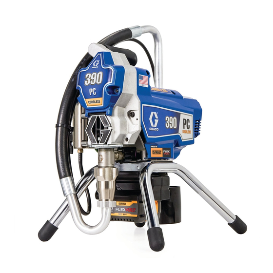
Cordless Electric Airless
Sprayers
For portable airless spraying of architectural paints and coatings (390 PC). For the
application of line striping materials (ES 500 Stencil). Not approved for use in
explosive atmospheres or hazardous (classified) locations. For professional use only.
390 PC Cordless Models: 25T804, 826280, 25T863, 25T943, 25T882, 25T805
ES 500 Stencil Models: 25U513, 25U514
3300 psi (228 bar, 22.8 MPa) Maximum Working Pressure
Important Safety Instructions
Read all warnings and instructions in this manual and related
manuals before using the equipment. Be familiar with the controls
and the proper usage of the equipment. Save these instructions.
Related Manuals
Manual
Description
311861
Gun (Contractor/FTX)
334599
Pump
3A6285
Gun (Contractor PC)
311254
Silver/Flex Plus
Use only genuine Graco replacement parts.
The use of non-Graco replacement parts may void warranty.
3A8179C
EN
Advertisement
Table of Contents

Related Manuals for Graco 25T804


Summary of Contents for Graco 25T804
- Page 1 (ES 500 Stencil). Not approved for use in explosive atmospheres or hazardous (classified) locations. For professional use only. 390 PC Cordless Models: 25T804, 826280, 25T863, 25T943, 25T882, 25T805 ES 500 Stencil Models: 25U513, 25U514 3300 psi (228 bar, 22.8 MPa) Maximum Working Pressure...
-
Page 2: Table Of Contents
Graco Standard Warranty ......42 Graco Information ........43... -
Page 3: Models
Models Models Hi-Boy Stand Battery Charger Voltage VDC Voltage VAC Model 25T804 390 PC Cordless 25T805 60 USA/CA 120 USA/CA ES 500 Stencil 25U513 NOVA 390 PC 826280 Cordless ES 500 Stencil 25U514 54 EMEA/UK 230 EMEA 390 PC Classic... -
Page 4: Important Grounding Information
Important Grounding Information Important Grounding Information Before using your sprayer read this Owners Manual for complete instructions on proper use and safety warnings. The following information is intended to help you understand when to use the grounding wire and clamp provided with your sprayer. -
Page 5: Warnings
All parts of the spray system, including the pump, hose assembly, spray gun, and objects in and around the spray area shall be properly grounded to protect against static discharge and sparks. Use Graco conductive or grounded high-pressure airless paint sprayer hoses. Follow Grounding Instructions, page 10. - Page 6 Check hoses and parts for signs of damage. Replace any damaged hoses or parts. • This system is capable of producing 3300 psi (228 bar, 22.8 MPa). Use Graco parts or accessories that are rated a minimum of 3300 psi (228 bar, 22.8 MPa).
- Page 7 Warnings PRESSURIZED ALUMINUM PARTS HAZARD Use of fluids that are incompatible with aluminum in pressurized equipment can cause serious chemical reaction and equipment rupture. Failure to follow this warning can result in death, serious injury, or property damage. • Do not use 1,1,1-trichloroethane, methylene chloride, other halogenated hydrocarbon solvents or fluids containing such solvents.
-
Page 8: Component Identification
Component Identification Component Identification Stand Models Siphon Hose ON/OFF Switch Pump Pressure Control Fluid Outlet Prime/Spray Valve Grounding Wire and Clamp Tip Guard Filter Spray Tip Finger Guard / TSL Fill Point W Ground Outlet Adapter Airless Hose Ground Plug Adapter Battery Extension Tube for Stencil Gun Trigger Lock... -
Page 9: Hi-Boy
Component Identification Hi-Boy Siphon Hose ON/OFF Switch Pump Pressure Control Fluid Outlet Prime/Spray Valve Grounding Wire and Clamp Tip Guard Filter Spray Tip Finger Guard / TSL Fill Point Pail Hook Airless Hose W Ground Outlet Adapter Battery Model/Serial Tag (Not shown, located Trigger Lock on bottom of unit.) M Drain Tube... -
Page 10: Grounding Instructions
Grounding Instructions Grounding Instructions (Oil-Based and Flammable Materials) A properly grounded electrical outlet can also be used as a true earth ground. Use the provided outlet adapter. Plug the adapter in to a grounded outlet. The equipment must be grounded to reduce Connect the grounding wire and clamp to the the risk of static sparking. -
Page 11: Pails
Grounding Instructions Pails Solvents and oil-based materials: follow local codes and regulations. Use only conductive metal pails, placed on a grounded surface such as concrete. Do not place pail on a non-conductive surface such as paper or cardboard which interrupts grounding continuity. -
Page 12: Pressure Relief Procedure
Pressure Relief Procedure Pressure Relief Procedure Turn the ON/OFF switch to the OFF Follow the Pressure Relief position. Power button is illuminated Procedure whenever you see this when ON. Wait 7 seconds for power to symbol. dissipate. This equipment stays pressurized until pressure is manually relieved. -
Page 13: Trigger Lock
Pressure Relief Procedure Trigger Lock Put drain tube in a pail. Turn prime/spray valve down. Leave prime/spray valve in down (drain) position until you are ready Always engage the trigger lock when sprayer to spray again. is stopped to prevent the gun from being triggered accidentally by hand or if dropped or bumped. -
Page 14: Setup
When unpacking sprayer for the first time or after long term storage perform setup procedure. When first setup is performed remove shipping plug from fluid outlet. Connect Graco airless hose to fluid outlet. Use two wrenches to tighten securely. ti24633a Use wrenches to tighten securely. - Page 15 Setup Remove tip guard. Fill throat packing nut with TSL to prevent premature packing wear. Do this daily or each time you spray. Place the TSL bottle nozzle into the top center opening in the grill at the front of the sprayer. Squeeze bottle to dispense enough TSL to fill the space between the pump rod and packing nut seal.
- Page 16 Setup Turn prime/spray valve down. 11. Turn pressure control to lowest setting. 12. Install battery, see Battery Installation and Removal, page 17. 13. Turn ON/OFF switch to ON position. 14. Increase pressure 1/2 turn to start motor. Allow fluid to flush through sprayer for one minute.
-
Page 17: Battery Installation And Removal
Setup Battery Installation and Install battery by aligning the battery pack with the rails inside the sprayer and Removal sliding it in until the battery pack is firmly seated. Ensure that it does not Always start with a fully charged Battery. disengage. -
Page 18: Startup
Startup Startup Increase pressure 1/2 turn to start motor. Allow paint or other material to circulate through sprayer until material flows out the drain tube. Perform Pressure Relief Procedure, page 12. Turn pressure control to lowest pressure. ti25231a Turn prime/spray valve horizontal. Disengage trigger lock. - Page 19 Startup Hold gun against grounded metal waste 10. Move gun to paint pail and trigger for 20 pail. Trigger gun at least 1 minute until seconds. Release trigger and allow paint appears. sprayer to build pressure. Engage trigger lock. High-pressure spray is able to inject toxins into the body and cause serious bodily injury.
-
Page 20: Operation
Operation Operation Spray Tip Installation Screw assembly onto gun. Tighten. To avoid serious injury from skin injection, do not put your hand in front of the Spray Tip when installing or removing the Spray Tip and Spray Tip Guard. Perform Pressure Relief Procedure, page 12. - Page 21 Operation Spray test pattern. Adjust pressure to Hold gun perpendicular, 10-12 in. (25-30 eliminate heavy edges. cm) from surface. Spray back and forth; overlap by 50%. ti24669a Use smaller tip size if pressure adjustment cannot eliminate heavy edges. ti24673a Trigger gun after moving. Release trigger before stopping.
-
Page 22: Clear Tip Clog
Operation Clear Tip Clog Engage trigger lock. Return Spray Tip to original position. Disengage trigger lock and continue spraying. To avoid injury, never point gun at your hand or into a rag! Release trigger. Engage trigger lock. Rotate Spray Tip. Disengage trigger lock. -
Page 23: Cleanup
Operation Cleanup Remove fluid intake and drain tube from paint, wipe excess paint off outside. To avoid serious injury from fire and explosion when using oil-based or flammable materials: • Do not spray solvents through the spray tip. Always remove tip guard and spray tip before flushing. - Page 24 Operation Increase pressure 1/2 turn to start motor. While continuing to trigger gun, turn Hold gun against grounded paint or prime/spray valve down. Then, release waste pail. Disengage trigger lock. gun trigger. Allow flushing fluid to Trigger gun and increase pressure until circulate until fluid comes out of drain the pump runs steady and flushing fluid tube clear.
- Page 25 Operation 11. Turn prime/spray valve horizontal. 13. Turn pressure control knob to the lowest Trigger gun into grounded flushing or pressure setting and turn ON/OFF waste pail for 20 seconds to purge fluid switch to OFF position. Power button is from hose.
-
Page 26: Cleaning Fluid Compatibility
Operation Cleaning Fluid 16. If flushing with water, flush again with ™ mineral spirits or Pump Armor to leave Compatibility a protective coating to prevent freezing or corrosion. • When spraying water-based materials, flush the system thoroughly with water. • When spraying oil-based or flammable materials, flush the system thoroughly with mineral spirits or compatible... -
Page 27: Maintenance
Maintenance Maintenance Routine maintenance is important to ensure proper operation of your sprayer. Maintenance includes performing routine actions which keep your sprayer in operation and prevents trouble in the future. Activity Interval Inspect/clean sprayer filter, fluid inlet strainer, and gun filter. Daily or each time you spray Inspect motor shield vents for blockage. -
Page 28: Troubleshooting
Troubleshooting Troubleshooting Mechanical/Fluid Flow Follow Pressure Relief Procedure, Check all possible problems and causes page 12, before checking or repairing. before disassembling the unit. What to Check What to Do If check is OK, go to next When check is not OK, Problem check refer to this column... - Page 29 Troubleshooting What to Check What to Do If check is OK, go to next When check is not OK, Problem check refer to this column Pump output is low Pump rod damage. Repair pump. See pump manual. Low stall pressure. Turn pressure knob fully clockwise.
- Page 30 Troubleshooting What to Check What to Do If check is OK, go to next When check is not OK, Problem check refer to this column Pump is difficult to prime Air in pump or hose. Check and tighten all fluid connections.
-
Page 31: Electrical
Troubleshooting Electrical Symptom: Sprayer does not run, stops Perform Pressure Relief Procedure, running, or will not shut off. page 12. Install fully charged battery, see Battery Installation and Removal, page 17. Turn the ON/OFF switch OFF, wait 30 seconds and then turn power back ON again (this ensures sprayer is in normal run mode). -
Page 32: Parts
Parts Parts 390 and ES 500 Stencil Stand Sprayer Parts Ref. Torque Ref. Torque Ref. Torque Ref. Torque 140-160 in-lbs. 10-20 in-lbs (1.13-2.26 40-50 in-lbs (4.5-5.6 23-27 in-lbs (2.6-3.1 N•m) (15.8-18.1 N•m) N•m) N•m) 80-90 in-lbs (9-10.2 8-10 in-lbs (0.9-1.13 N•m) 25-35 in-lbs (2.8-4 N•m) N•m) 3A8179C... - Page 33 17C539 COVER, front head 23 * SHIELD, motor, includes 87, 100422 WASHER, lock 12, 48, 84, 89, 90 19D606 BATTERY COMPARTMENT 25U300 Models: 25T804, 25T863, 17R614 FASTENERS, battery 25T943, 25T882, 25U513, compartment 25U514 115477 FASTENER 826283 Models: 826280 17P924 LABEL, A+...
- Page 34 Parts 390 Hi-Boy Sprayers Parts Ref. Torque Ref. Torque Ref. Torque Ref. Torque 140-160 in-lbs. 10-20 in-lbs (1.13-2.26 40-50 in-lbs (4.5-5.6 23-27 in-lbs (2.6-3.1 N•m) (15.8-18.1 N•m) N•m) N•m) 80-90 in-lbs (9-10.2 8-10 in-lbs (0.9-1.13 N•m) 25-35 in-lbs (2.8-4 N•m) N•m) 3A8179C...
- Page 35 Parts 390 Hi-Boy Sprayer Parts List Ref. Part Description Qty. Ref. Part Description Qty. 15K092 TUBE, drain 107434 BEARING, thrust 19D605 SWITCH, power 25T886 BRACKET, cover O-RING 117501 SCREW, mach, hex hd. 16V903 CONDUIT, corrugated 235004 STRAINER, 3/4-16 unf 20A450 GASKET 115099 WASHER...
- Page 36 Parts Control Box and Filter Ref. Torque Ref. Torque Ref. Torque Ref. Torque 140-160 in-lbs. 130-140 in-lbs (14.7-16.9 48-72 in-lbs (5.4-8.1 (15.8-18.1 N•m) N•m) N•m) 3A8179C...
- Page 37 Qty. Ref. Part Description Qty. 162453 NIPPLE, (1/4 npsm x 117828 PACKING, o-ring 1/4 npt) (Models 111600 PIN, grooved 25T804, 826280, 277364 GASKET, seat, valve 25T863, 25T943, MANIFOLD, fluid 25T882) 17C590 Sprayer (Models: 196181 NIPPLE, (1/4 npsm x 25T804, 25T805,...
-
Page 38: Gun, Hose And Labels
Ref. 50, Ref. 52 Label, Medical Label, (Series) in. x 50 ft Gun, Spray Label, Top Label, Front Side Alert Danger 25T804 & 240794 20A479 20A330 20A328 20A329 222385 # 20A030 # 25T805 & 25T863 $ 240794 288438 20A428... -
Page 39: Wiring Diagram
Wiring Diagram Wiring Diagram 3A8179C... -
Page 40: Technical Specifications
Technical Specifications Technical Specifications 390 PC / ES 500 Stencil Cordless Metric Sprayer Maximum fluid working pressure 390 PC / ES 500 Stencil Cordless 3300 psi 228 bar, 22.8 MPa Maximum Delivery 390 PC / ES 500 Stencil Cordless 0.47 gpm 1.8 lpm Maximum Tip Size 390 PC / ES 500 Stencil Cordless... -
Page 41: California Proposition 65
California Proposition 65 California Proposition 65 CALIFORNIA RESIDENTS WARNING: Cancer and reproductive harm – www.P65warnings.ca.gov. 3A8179C... -
Page 42: Graco Standard Warranty
Graco’s written recommendations. This warranty does not cover, and Graco shall not be liable for general wear and tear, or any malfunction, damage or wear caused by faulty installation, misapplication, abrasion, corrosion, inadequate or improper maintenance, negligence, accident, tampering, or substitution of non-Graco component parts. -
Page 43: Graco Information
Graco Information Graco Information For the latest information about Graco products, visit www.graco.com. For patent information, see www.graco.com/patents. TO PLACE AN ORDER, contact your Graco distributor or call 1-800-690-2894 to identify the nearest distributor. 3A8179C... - Page 44 Original instructions. This manual contains English. MM 3A8179 Graco Headquarters: Minneapolis International Offices: Belgium, China, Japan, Korea GRACO INC. AND SUBSIDIARIES • P.O. BOX 1441 • MINNEAPOLIS MN 55440-1441 • USA Copyright 2021, Graco Inc. All Graco manufacturing locations are registered to ISO 9001. www.graco.com...