Table of Contents
Advertisement
Quick Links
Operation, Repair, Parts
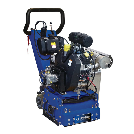
GrindLazer
For removal of materials from flat horizontal concrete and asphalt surfaces. Not approved for
use in explosive atmospheres or hazardous (classified) locations. Gas/propane units not for
use indoors or in enclosed spaces. For professional use only.
Models 25P474 / 25R100 - Graco DC1538 G DCS (High speed / Standard speed)
Models 25P475 / 25R101 - Graco DC1525 P DCS (High speed / Standard speed)
Models 25P476 / 25R102 - Graco DC1520 E DCS 480V (High speed / Standard speed)
Models 25P783 / 25R103 - Graco DC1520 E DCS 380V (High speed / Standard speed)
Maximum Working Pressure: 1750 psi (121 bar, 12.1 MPa)
Important Safety Instructions
Read all warnings and instructions in this manual and in the Kohler engine manual before
using the equipment. Be familiar with the controls and the proper usage of the equipment.
Save these instructions.
62 590 13 - Kohler Owner's Manual (Gas)
DC1538 G DCS
™
Related Manuals:
24 590 52- Kohler Owner's Manual (Propane)
DC1525 P DCS
(Drums and cutters sold separately)
www.graco.com/techsupport
3A7600C
DC1520 E DCS
EN
Advertisement
Table of Contents

Related Manuals for Graco GrindLazer 25P474


Summary of Contents for Graco GrindLazer 25P474
- Page 1 Models 25P475 / 25R101 - Graco DC1525 P DCS (High speed / Standard speed) Models 25P476 / 25R102 - Graco DC1520 E DCS 480V (High speed / Standard speed) Models 25P783 / 25R103 - Graco DC1520 E DCS 380V (High speed / Standard speed) Maximum Working Pressure: 1750 psi (121 bar, 12.1 MPa)
-
Page 2: Table Of Contents
Parts List - Guidebar / Vacuum Hose Assemblies Graco Information ......74 (All Models) ......39... -
Page 3: Warnings
Warnings Warnings The following warnings are for the setup, use, grounding, maintenance, and repair of this equipment. The exclamation point symbol alerts you to a general warning and the hazard symbols refer to procedure-specific risks. When these symbols appear in the body of this manual or on warning labels, refer back to these Warnings. Product-specific hazard symbols and warnings not covered in this section may appear throughout the body of this manual where applicable. - Page 4 Warnings WARNING SKIN INJECTION HAZARD High-pressure fluid from hose leaks, or ruptured components will pierce skin. This may look like just a cut, but it is a serious injury that can result in amputation. Get immediate surgical treatment. • Inspect hose before each use for cuts, bulges, kinks or any other damage. •...
-
Page 5: Gasoline/Propane Engine Warnings
Warnings Gasoline/Propane Engine Warnings WARNING FIRE AND EXPLOSION HAZARD -- GASOLINE Flammable fumes, such as solvent and paint fumes, in work area can ignite or explode. To help pre- vent fire and explosion: • Use equipment only outdoors. Never use indoors or in enclosed spaces. •... -
Page 6: Electric Motor Warnings
Warnings Electric Motor Warnings DANGER SEVERE ELECTRIC SHOCK HAZARD This equipment is powered by more than 240 V. Contact with this voltage will cause death or serious injury. • Turn off and disconnect power cord before servicing equipment. • Connect only to grounded electrical outlets. •... -
Page 7: Component Identification
Component Identification Component Identification DC1538 G DCS (Gas) See Lifting Instructions, page 10. Component Component Engine Kill Button Adjustable Handlebar Manual Height Adjustment Handlebar Adjustable Bolts Battery DCS Control Vacuum Port Hour Meter / Tachometer Lift Carriage with Swivel Casters Home Button Self-Propelled Drive Wheels Zero Button... -
Page 8: Dc1525 P Dcs (Propane)
Component Identification DC1525 P DCS (Propane) See Lifting Instructions, page 10. Component Component Engine Kill Button Adjustable Handlebar Manual Height Adjustment Handlebar Adjustment Bolts Battery DCS Control Vacuum Port Hour Meter / Tachometer Lift Carriage with Swivel Casters Home Button Self-Propelled Drive Wheels Zero Button Removable Side Plate... -
Page 9: Dc1520 E Dcs (Electric)
Component Identification DC1520 E DCS (Electric) See Lifting Instructions, page 10. Component Component Manual Height Adjustment Adjustable Handlebar Vacuum Port Handlebar Adjustment Bolts Lift Carriage with Swivel Casters DCS Control Self-Propelled Drive Wheels Home Button Removable Side Plate Zero Button Hydraulic Drive Pump Cut Depth Button Hydraulic Reservoir... -
Page 10: Setup
Setup Setup Propane Tank Lifting Instructions Propane (LP gas) supply tank not provided by Graco. • Only lift the equipment using all available lift points. Supply tank must be vertically mounted and vapor The lift chains must be angled at least 45° from the withdrawal type. -
Page 11: Handlebar Adjustment
Setup Handlebar Adjustment Engine Kill Button (Gas/Propane) The handlebars are equipped with a high-density In the event of a malfunction or an accident (such as the vibration suppression material to reduce operator machine operator falling or losing footing), the fatigue. To adjust the handlebars to a new position for GrindLazer is equipped with a corded Engine Kill Button. -
Page 12: Drum Installation/Replacement
Setup Drum Installation/Replacement 4. Remove six hex head cap screws from the Side Plate using the 9/16” socket or wrench. 5. Remove the Side Plate (this may require the rubber mallet to break it loose). Gas/Propane: To avoid injury from unexpected start 6. -
Page 13: Dcs Control
Setup DCS Control Zero Button Buttons on the DCS Control have two functions, quick press and long press. Quick press refers to pressing the Quick Press: Takes the drum to the work surface. button and releasing the button quickly, while long press is pressing the button and holding the button for two or more seconds. - Page 14 Setup Cut Depth Button Up Arrow Button* Quick Press: Raises the drum by 0.01” (0.25mm, 10 Quick Press: Takes the drum to the Cut Depth Target. mil). Long Press: Raises the drum to Home position. Long Press: If at or above zero point: Opens new screen to select desired cut depth using up/down buttons.
- Page 15 Setup Menu Screens Menu Screen #3 - Model Select Your GrindLazer model name can be found on the han- To display the Menu Screens, hold down Home Button dlebar dashboard label. Select the model on the DCS from the Run Screen. To save menu settings and return Control which matches the model you have.
- Page 16 Setup Menu Screen #5 - Error Codes Error Codes E04: High Voltage Displays the most recent error code and the total num- E05: High Motor Current ber of times that error has occurred. Cycle through pre- E08: Low Voltage vious error codes using Up/Down Buttons. E09: Hall Sensor Error E12: High Current (short circuit) E31: Home Button Error...
-
Page 17: Operation
Operation Operation If the Engine Does Not Start • Turn the ON/OFF Switch on the Control Panel to ON. • Check engine for proper gas and oil levels. • Check the spark plug. Make sure socket areas are clean and clear of debris, and the proper gap is set. Do not start machine while cutter head is in contact Replace if needed. -
Page 18: When Operating
The drum assembly must be removed daily and inspected for drum wear, hole elongation and possible weld separation. Replace the cutter shafts every 40 hours, or prior to any drum wear. If the drum’s center holes are elongated, order another Graco cutter drum. 3A7600C... -
Page 19: Dcs Instructions
Operation DCS Instructions Set Cut Depth Target: Quick press the Zero Button to take the drum to the work Each time the DCS Control is turned on, the DCS actua- surface. Set the Cut Depth Target by: tor will travel to the Home position. 1. - Page 20 Operation The DCS Control is now ready to grind/scarify. 3. Insert 6mm hex key into the port the screw plug was removed from. NOTE: The Zero Point and Cut Depth are referenced • One revolution of the hex key results in 1/16” (1.6 from the Home position.
-
Page 21: Repair
Repair Repair 3. Clean the exterior of the machine so you can locate all of the appropriate parts. 4. Using a 9/16” socket or wrench, remove the four hex Gas/Propane: To avoid injury from unexpected start bolts attaching the belt cover to the side of the up, disable engine as follows: 1) Turn DCS Power machine. -
Page 22: Hydraulic Belt Replacement (Electric Models Only)
Repair 7. Put the belt cover back in place and secure the four 4. To tighten the belt, slide the bracket up and lightly hex nuts with the 9/16” socket or wrench. tighten the hex bolts. To ensure alignment of the pulleys, use a ruler or a straight edge and place it on the faces of both pulleys and adjust the bracket Deflection... -
Page 23: Bearing Housing Replacement
Repair Bearing Housing Replacement 5. With the shaft rotation locked, use the 7/32” hex key to remove the two set screws on the drive pulley. Once removed, insert one of the set screws into the Tools needed: hole directly above the keyway to back out the bushing. -
Page 24: Drive Pulley Replacement
Repair Drive Pulley Replacement Electric Models Standard Speed: Use the 48-tooth pulley on the motor The drive pulleys must be replaced to change between shaft and the 56-tooth pulley on the drum shaft with the high speed and standard speed. 1200 mm belt. -
Page 25: Maintenance Checklist
Maintenance Checklist Maintenance Checklist • Maintain proper engine oil and crankcase levels. Change every 25-50 hours (see Kohler manual). • Clean spark plugs regularly, and set the proper gap Gas/Propane: To avoid injury from unexpected start (see Kohler manual). up, disable engine as follows: 1) Turn DCS Power Switch OFF. -
Page 26: Purge Procedures
Maintenance Checklist Purge Procedures 2. With the bypass valve closed and the engine/motor running, slowly move the directional control in both forward and reverse directions 5 to 6 times. Check the Due to the effects air has on efficiency in hydrostatic drive oil level, and add hydraulic fluid as required after applications, it is critical that air is removed or purged from stopping engine/motor. -
Page 27: Recycling And Disposal
Recycling and Disposal Recycling and Disposal Rechargeable Battery Disposal End of Product Life Do not place batteries in the trash. Recycle batteries At the end of the product’s useful life, dismantle and according to local regulations. In the USA and Canada, recycle it in a responsible manner. -
Page 28: Dcs Control Translations
DCS Control Translations DCS Control Translations English Español Français Deutsche International FINDING HOME ENCONTRANDO INICIO TROUVER LE DÉBUT START FINDEN HOME INICIO START DÉBUT DEPTH ALTURA TIEFE HAUTEUR TARGET OBJETIVO ZIEL OBJECTIF ZERO CERO NULL ZÉRO SEL MODEL MODELO MODELL MODELE LANGUAGE IDIOMA... - Page 29 DCS Control Translations English Español Français Deutsche International FREQUENCY FRECUENCIA ANZHAL FRÉQUENCE HIGH CURRENT ALTA CORRIENTE HOHER STROM COURANT ÉLEVÉ LOW VOLTAGE BAJO VOLTAJE NIEDERSPANNUNG BASSE TENSION HIGH VOLTAGE ALTO VOLTAJE HOCHSPANNUNG HAUTE TENSION HALL SENSORS SENSORES DE HALL HALL-SENSOREN CAPTEURS DE HALL HOME BUTTON BOTÓN DE INICIO...
-
Page 30: Troubleshooting
Troubleshooting Troubleshooting Gas/Propane: To avoid injury from unexpected start up, disable engine as follows: 1) Turn ignition OFF. 2) Disconnect spark plug wires. 3) Disconnect negative (-) battery cable from battery. Electric: To avoid injury from unexpected start up, disconnect power plug before you service your machine. - Page 31 Troubleshooting Problem Cause Solution Pulley is misaligned Re-align pulley Drive belt wearing prematurely Wrong belt Order new belt Hydraulic fluid level may be low Ensure hydraulic fluid level reservoir is filled to the proper level V-belt to hydraulic pump is slipping or dam- Check V-belt, replace if damaged Machine will not move in forward aged...
-
Page 32: Dcs Error Codes
Troubleshooting DCS Error Codes To clear an error code on the DCS Control: 1. Turn DCS Power Switch to OFF. 2. Address/Fix the issue. 3. Turn DCS Power Switch to ON. Error Cause Solution E04: High Voltage Battery is damaged. Replace battery. -
Page 33: Dcs Actuator Rod Does Not Move
Troubleshooting DCS Actuator Rod Does Not Move Use this flow chart if the DCS Actuator Rod does not move or if the DCS displays error code E09 (Hall Sensor Error). Reference Wiring Diagram, page 68. Turn power switch to OFF. Remove the blue shroud behind the DCS Control. Ensure you have a good 12V battery installed. -
Page 34: Parts - Main Housing Assembly (All Models)
Parts - Main Housing Assembly (All Models) Parts - Main Housing Assembly (All Models) Torque to 23-27 ft-lbs (31.2-36.6N·m) Torque to 40 ft-lbs (54.2 N·m) Torque to 90-110 in-lbs (10.2-12.4 N·m) ti38091a 3A7600C... -
Page 35: Parts List - Main Housing Assembly (All Models)
Parts - Main Housing Assembly (All Models) Parts List - Main Housing Assembly (All Models) Ref. Part Description Qty. Ref. Part Description Qty. 18B352 STRIPS, front, brush 18B284 PLATE, side 107139 BOLT, carriage, 1/4”-20x1” 18B345 SKIRT, fixed, left side 17W021 WASHER, fender, bend, 1/4 x 1” 18B370 PLATE, retaining, left skirt 102040... -
Page 36: Parts - Front Wheel / Wheel Carrier Assemblies
Parts - Front Wheel / Wheel Carrier Assemblies (All Models) Parts - Front Wheel / Wheel Carrier Assemblies (All Models) Torque to 40 ft-lbs (54.2 N·m) Torque to 34 ft-lbs (46.1 N·m) ti38092a ti38094a 3A7600C... -
Page 37: Parts List - Front Wheel / Wheel Carrier Assemblies (All Models)
Parts - Front Wheel / Wheel Carrier Assemblies (All Models) Parts List - Front Wheel / Wheel Carrier Assemblies (All Models) Ref. Part Description Qty. Ref. Part Description Qty. 169468 WASHER, flat, 3/4” 17W020 WASHER, flat, 1/4” 18B380 AXLE, wheel 100016 WASHER, lock, 1/4”... -
Page 38: Parts - Guidebar / Vacuum Assemblies
Parts - Guidebar / Vacuum Assemblies (All Models) Parts - Guidebar / Vacuum Assemblies (All Models) Torque to 40 ft-lbs (54.2 N·m) Torque to 90-110 in-lbs (10.2-12.4 N·m) Torque to 15 ± 5 ft-lbs (20.3 ± 6.8 N·m) ti38093a ti38096a 3A7600C... -
Page 39: Parts List - Guidebar / Vacuum Hose Assemblies (All Models)
Parts - Guidebar / Vacuum Assemblies (All Models) Parts List - Guidebar / Vacuum Hose Assemblies (All Models) Ref. Part Description Qty. Ref. Part Description Qty. 18B178 ACTUATOR, 80mm 100021 SCREW, hex, cap, 1/4”-20 x 1” 18A114 17W020 WASHER, flat, 1/4” 17Y962 PIN, cotter, bow tie 100016... -
Page 40: Parts - Hydraulic Motor / Rear Assembly
Parts - Hydraulic Motor / Rear Assembly (All Models) Parts - Hydraulic Motor / Rear Assembly (All Models) Torque to 90-110 in-lbs (10.2-12.4 N·m) See manufacturer’s package Torque to 15 ± 5 ft-lbs (20.3 ± 6.8 N·m) ti38097a ti38095a 3A7600C... -
Page 41: Parts List - Hydraulic Motor / Rear Assembly (All Models)
Parts - Hydraulic Motor / Rear Assembly (All Models) Parts List - Hydraulic Motor / Rear Assembly (All Models) Ref. Part Description Qty. Ref. Part Description Qty. 18B373 BEARING, drive wheel, flanged 17W020 WASHER, flat, 1/4” 18B507 SCREW, hex, cap, 1/2”-13 x 2” 100016 WASHER, lock, 1/4”... -
Page 42: Parts - Support System / Hydraulic Tank
Parts - Support System / Hydraulic Tank (All Models) Parts - Support System / Hydraulic Tank (All Models) Torque to 23-27 ft-lbs (31.2-36.6N·m) Torque to 90-110 in-lbs (10.2-12.4 N·m) ti38098a ti38099a 3A7600C... -
Page 43: Parts List - Support System / Hydraulic Tank (All Models)
Parts - Support System / Hydraulic Tank (All Models) Parts List - Support System / Hydraulic Tank (All Models) Ref. Part Description Qty. Ref. Part Description Qty. 110838 NUT, nylock, 5/16”-18 17W020 WASHER, flat, 1/4” 124227 SCREW, hex, 5/16”-18 x 1” 100023 WASHER, flat, 3/8”... -
Page 44: Parts - Motor / Hydraulic Assemblies (Gas)
Parts - Motor / Hydraulic Assemblies (Gas) Parts - Motor / Hydraulic Assemblies (Gas) Torque to 90 ± 5 in-lbs (10.2 ± 0.6 N·m) Torque to 30 ± 5 ft-lbs (40.7 ± 6.8 N·m) Torque to 40 ± 5 ft-lbs (54.2 ±... -
Page 45: Parts List - Motor / Hydraulic Assemblies (Gas)
Parts - Motor / Hydraulic Assemblies (Gas) Parts List - Motor / Hydraulic Assemblies (Gas) Ref. Part Description Qty. Ref. Part Description Qty. 18B368 ARM, pump control 17W020 WASHER, flat, 1/4” 18B516 SCREW, hex, cap, 1.25 x 16mm 102040 NUT, nylock, 1/4-20 18B423 BALL, joint 19B308... -
Page 46: Parts - Hydraulic Fittings / Fuel Tank Assemblies
Parts - Hydraulic Fittings / Fuel Tank Assemblies (Gas) Parts - Hydraulic Fittings / Fuel Tank Assemblies (Gas) Torque to 90 ± 5 in-lbs (10.2 ± 0.6 N·m) Torque to 23 - 27 ft-lbs (31.2 ± 36.6 N·m) Torque to 15 ± 5 ft-lbs (20.3 ±... -
Page 47: Parts List - Hydraulic Fittings / Fuel Tank Assemblies (Gas)
Parts - Hydraulic Fittings / Fuel Tank Assemblies (Gas) Parts List - Hydraulic Fittings / Fuel Tank Assemblies (Gas) Ref. Part Description Qty. Ref. Part Description Qty. 116830 FILTER, oil 100527 WASHER, flat, 5/16” 18B300 HOSE, hydraulic, 20” 110838 NUT, nylock, 5/16-18 18B301 HOSE, hydraulic, 20”... -
Page 48: Parts - Pulley Assemblies (Gas)
Parts - Pulley Assemblies (Gas) Parts - Pulley Assemblies (Gas) High Speed Torque to 90 ± 5 in-lbs (10.2 ± 0.6 N·m) Torque to 30 ± 5 ft-lbs (40.7 ± 6.8 N·m) See manufacturer’s 63 39 40 package 38 39 40 ti37949b Standard Speed 69 71 70... -
Page 49: Parts List - Pulley Assemblies (Gas)
Parts - Pulley Assemblies (Gas) Parts List - Pulley Assemblies (Gas) High Speed (Model 25P474) Ref. Part Description Qty. Ref. Part Description Qty. 18A501 SCREW, socket head cap, 100023 WASHER, flat, 3/8” 5/8-18 x 1” 100133 WASHER, lock, 3/8” 19C103 BELT 100101 SCREW, hex, cap, 3/8-16 x 1”... -
Page 50: Parts - Dashboard / Battery Assemblies (Gas)
Parts - Dashboard / Battery Assemblies (Gas) Parts - Dashboard / Battery Assemblies (Gas) 3A7600C... -
Page 51: Parts List - Dashboard / Battery Assemblies (Gas)
Parts - Dashboard / Battery Assemblies (Gas) Parts List - Dashboard / Battery Assemblies (Gas) Ref. Part Description Qty. Ref. Part Description Qty. 18Y705 FOAM, urethane, 1/4” 18B394 CABLE, vernier, control 115753 BATTERY, 35 AH agm 17W073 SWITCH, kill 18A786 STRAP, Velcro, 2”... -
Page 52: Parts - Motor / Hydraulic Assemblies (Propane)
Parts - Motor / Hydraulic Assemblies (Propane) Parts - Motor / Hydraulic Assemblies (Propane) Torque to 90 ± 5 in-lbs (10.2 ± 0.6 N·m) Torque to 30 ± 5 ft-lbs (40.7 ± 6.8 N·m) Torque to 40 ± 5 ft-lbs (54.2 ±... -
Page 53: Parts List - Motor / Hydraulic Assemblies (Propane)
Parts - Motor / Hydraulic Assemblies (Propane) Parts List - Motor / Hydraulic Assemblies (Propane) Ref. Part Description Qty. Ref. Part Description Qty. 18B368 ARM, pump control 100527 WASHER, flat, 5/16” 18B516 SCREW, hex, cap, 1.25 x 16mm 110838 NUT, nylock, 5/16-18 18B445 FITTING, adapter 124227 SCREW, hex, cap, 5/16-18 x 1 18B423 BALL, joint... -
Page 54: Parts - Propane Tank / Dashboard Assemblies
Parts - Propane Tank / Dashboard Assemblies (Propane) Parts - Propane Tank / Dashboard Assemblies (Propane) Torque to 23 - 27 ft-lbs (31.2 ± 36.6 N·m) ti38079a ti38081a 3A7600C... -
Page 55: Parts List - Propane Tank / Dashboard Assemblies (Propane)
Parts - Propane Tank / Dashboard Assemblies (Propane) Parts List - Propane Tank / Dashboard Assemblies (Propane) Ref. Part Description Qty. Ref. Part Description Qty. 18B120 SWITCH, key 100527 WASHER, flat, 5/16” 17Z193 SWITCH, power, assembly 110838 NUT, nylock, 5/16-18 17Z340 TOGGLE, boot 124227... -
Page 56: Parts - Pulley Assemblies (Propane)
Parts - Pulley Assemblies (Propane) Parts - Pulley Assemblies (Propane) High Speed 54 55 Torque to 90 ± 5 in-lbs (10.2 ± 0.6 N·m) Torque to 30 ± 5 ft-lbs (40.7 ± 6.8 N·m) See manufacturer’s package ti38078b Standard Speed 67 144 67 65 68 69 67... -
Page 57: Parts List - Pulley Assemblies (Propane)
Parts - Pulley Assemblies (Propane) Parts List - Pulley Assemblies (Propane) High-Speed (Model 25P475) Ref. Part Description Qty. Ref. Part Description Qty. 18A504 SPACER, clutch 100023 WASHER, flat, 3/8” 18A500 WASHER, clutch 100133 WASHER, lock, 3/8” 18A501 SCREW, socket head cap, 102637 SCREW, hex, cap, 3/8-16 x 1.5”... -
Page 58: Parts - Battery Assembly (Propane)
Parts - Battery Assembly (Propane) Parts - Battery Assembly (Propane) ti38080a 3A7600C... -
Page 59: Parts List - Battery Assembly (Propane)
Parts - Battery Assembly (Propane) Parts List - Battery Assembly (Propane) Ref. Part Description Qty. Ref. Part Description Qty. 110823 SCREW, low profile, 1/4-20 x 1” 17Y121 BOX, battery 801958 TERMINAL, battery, protector, 18Y704 FOAM, urethane, 1/2” 18Y701 FOAM, urethane, 1/4” 801959 TERMINAL, battery, protector, 18Y705... -
Page 60: Parts - Electrical Components (Electric)
Parts - Electrical Components (Electric) Parts - Electrical Components (Electric) 2X 70 12 13 4X 3 ti38104a Torque to 90 ± 5 in-lbs (10.2 ± 0.6 N·m) Torque to 40 ± 5 ft-lbs (54.2 ± 6.8 N·m) Torque to 23 - 27 ft-lbs (31.2 ±... -
Page 61: Parts List - Electrical Components (Electric)
Parts - Electrical Components (Electric) Parts List - Electrical Components (Electric) Ref. Part Description Qty. Ref. Part Description Qty. 18B763 STRAIN, wire, relief, .25-.38 100133 WASHER, lock, 3/8” 18B762 STRAIN, wire, relief, .63-.75 100023 WASHER, flat, 3/8” 102360 WASHER, flat, #10 117501 SCREW, hex, hd, 8-32 x 1/2”... -
Page 62: Parts - Hydraulic Motor Assemblies (Electric)
Parts - Hydraulic Motor Assemblies (Electric) Parts - Hydraulic Motor Assemblies (Electric) Torque to 40 ± 5 ft-lbs (54.2 ± 6.8 N·m) Torque to 15 ± 5 ft-lbs (20.3 ± 6.8 N·m) ti38106a ti38107a 3A7600C... -
Page 63: Parts List - Hydraulic Motor Assemblies (Electric)
Parts - Hydraulic Motor Assemblies (Electric) Parts List - Hydraulic Motor Assemblies (Electric) Ref. Part Description Qty. Ref. Part Description Qty. 18B339 KEY, 3/16 x .75 100133 WASHER, lock, 3/8” 101566 NUT, nylock, 3/8”-16 100023 WASHER, flat, 3/8” 102637 SCREW, hex, cap, 3/8”-16 x 1.5” 18B584 BELT, hydraulic, pulley 18B490 WASHER, flat, 3/8”... -
Page 64: Parts - Hydraulic Assembly (Electric)
Parts - Hydraulic Assembly (Electric) Parts - Hydraulic Assembly (Electric) Torque to 90 ± 5 in-lbs (10.2 ± 0.6 N·m) Torque to 15 ± 5 ft-lbs (20.3 ± 6.8 N·m) ti38108a 3A7600C... -
Page 65: Parts List - Hydraulic Tank Assembly (Electric)
Parts - Hydraulic Assembly (Electric) Parts List - Hydraulic Tank Assembly (Electric) Ref. Part Description Qty. Ref. Part Description Qty. 116828 HEAD, filter, spin-on 18B585 MOUNT, control, cable 100022 SCREW, hex, 1/4”-20 x .75” 18B729 PUMP, hydraulic 100016 WASHER, lock, 1/4” 18B443 FITTING, adapter 17W020... -
Page 66: Parts - Pulley Assemblies (Electric - 480V & 380V)
Parts - Pulley Assemblies (Electric - 480V & 380V) Parts - Pulley Assemblies (Electric - 480V & 380V) High Speed ti38109a Torque to 90 ± 5 in-lbs (10.2 ± 0.6 N·m) Torque to 30 ± 5 ft-lbs (40.7 ± 6.8 N·m) Standard Speed See manufacturer’s package... - Page 67 Parts - Pulley Assemblies (Electric - 480V & 380V) Parts List - Pulley Assemblies (Electric 480V & 380V) High Speed (Models 25P476 & 25P783) Ref. Part Description Qty. Ref. Part Description Qty. 19B362 BELT, power grip 100133 WASHER, lock, 3/8” 19B383 GUARD, belt 100023...
-
Page 68: Wiring Diagram
Wiring Diagram Wiring Diagram Gas Models 3A7600C... -
Page 69: Propane Models
Wiring Diagram Propane Models 3A7600C... -
Page 70: Electric Models (480V)
Wiring Diagram Electric Models (480V) 3A7600C... -
Page 71: Electric Models (380V)
Wiring Diagram Electric Models (380V) 3A7600C... -
Page 72: Technical Data
Technical Data Technical Data DC1538 G DCS (Models 25P474 / 25R100) Maximum Working Pressure 1750 psi 121 bar, 12.1 MPa Noise level (dBa) Sound power 107 dBa per ISO 3744 Sound pressure 91 dBa measured at 3.1 feet (1m) Vibration level* Right/Left Hand 14.5 m/sec * Vibration measured per ISO 5349 based on 8 hour daily exposure... - Page 73 Technical Data California Proposition 65 CALIFORNIA RESIDENTS WARNING: Cancer and reproductive harm – www.P65warnings.ca.gov. 3A7600C...
-
Page 74: Graco Standard Warranty
With the exception of any special, extended, or limited warranty published by Graco, Graco will, for a period of twelve months from the date of sale, repair or replace any part of the equipment determined by Graco to be defective.