Table of Contents
Advertisement
Quick Links
HF
TRANSCEIVER
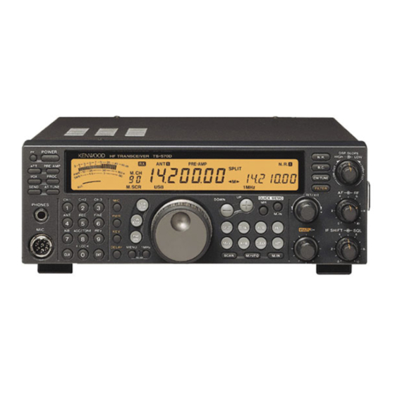
TS-5700
SERVICE
P h o n e jac k
(E11-0438-05)
Key t o p
(K29-5096-03)
Foot (F)
(J02-0442-04)
MIC c o n n ecto r
(EOG-0858-15)
CIRCUIT DESCRIPTION ................................... 2
DESCRIPTION OF COMPONENTS ................ 30
SEMICONDUCTOR DATA .............................. 36
PARTS LIST ..................................................... 44
EXPLODED VIEW ........................................... 61
................................. .. .. ............... ....
ADJUSTMENT ............................................... 64
TERMINAL FUNCTION ................................... 78
I
PC BOARD VIEWS
CIRCUIT DIAGRAMS
LCD ASSV (B38-0765-05) .......................... 81
MANUAL
Meta l l ic ca b i n et (U p p e r )
(A01-2117-02)
x
2
Key t o p
(K29-5097-03)
CONTE NTS
63
KENWOOD
© 1996-9
851-8343-00
Key t o p
(K29-5095-03)
Pa n l e assy
(A62-0459-03)
Key t o p
(K29-5110-03)
F o ot (F)
K n o b
(J02-0440-04)
(K29-5100-03)
FINAL UNIT (X45-353X-XX) (B/2) ............ 84
TX-RX UNIT (X57-500X-XX) (B/2) ............ 84
FINAL UNIT (X45-353X-XX) (A/2) ............ 85
CONTROL UNIT (X53-369X-XX) ............... 93
TX-RX UNIT (X57-500X-XX) (A/2) .......... 101
BLOCK DIAGRAM ........................................ 113
LEVEL DIAGRAM ....... ......................... ....... .. 115
VS-3 (VOICE SYNTHESIZER UNIT) ............ 117
DRU-3A (DIGITAL RECORDING UNIT) ....... 117
SPECIFICATIONS . . . . . . . .. . . . . . . . . . . . . . . . . . . . . . . . . . . . . . . . . 119
PRINTED IN JAPAN
(N)
1331
K n o b (O ut)
x
(K29-5099-04)
3
x
2
Advertisement
Table of Contents

Related Manuals for Kenwood TS-5700


Summary of Contents for Kenwood TS-5700
-
Page 1: Table Of Contents
KENWOOD TRANSCEIVER TS-5700 MANUAL SERVICE PRINTED IN JAPAN © 1996-9 851-8343-00 1331 P h o n e jac k Meta l l ic ca b i n et (U p p e r ) Key t o p (E11-0438-05) (A01-2117-02) -
Page 2: Circuit Description
TS -57 0 0 CI R CU IT D ES CR I PTION Frequ ency Confi g u rati o n The TS-570D utilizes double conversion in all trans When the transmitter is used in SSB mode or in mit modes and non-FM receive modes, and triple con other modes, likewise, the frequency is determined by version in FM mode. - Page 4 � 8.83MHz 73.08-103.05MHz 64.22MHz 73.08- 65.54- 103.05MHz 66.04MHz 0545 0533 IC506 2SC27141YI SN76514N 2SC2714(Y) :::; :::; :::; 00,..: ,...: """ "' ::!! r--: oo..: 73.08- 65.54- <(CD U 84.04MHz 66.04MHz VC01A 0528 >>> 5.54-6.04MHz IC505 0519 2SK18751VI "'O UPC1686G 2SC2412KISI ..
- Page 5 TS-5700 CIRCU IT D ES CRI PTI O N • DDS C i rcu it Confi g u ration 6) Phase data operatio n The DDS IC has been developed with standard cells The target frequency phase data i s output by accu...
- Page 6 TS-570 0 CIRC U IT D ESCRI PTI O N • (l0 1 1 ) L01 Loca l Si g n a l s a n d CAR) 2) CAR Table 3 lists the DDS1 frequency configuration. Table 2 lists the DDS2 frequency configuration. The 8.
- Page 8 TS-570 0 CIRCUIT D ES CRIPTION • I F Filter Rat i n g s (TX-RX U n it) XF2: L71-0266-05 XF3: L71-0208-15 Item XF1 : L71-0401-05 883 0 k H z N o m i n a l c e n t e r f re q u e n cy 73 0 5 M H z 8830 k H z ±...
- Page 9 TS-5700 TS-5700 CIRCUIT DESCRIPTION ---J------- ANT1 ANT2 TX- R X UNIT X57-500X-XX 0800,802,804 Q805 Q806 D800 Q807 RU201 2SC27141Ylx3 2SC2714IYI MA716 2SC2412KISI DTA1 14EK NB IN IC15: KCD11 (SSB,AM HIC) -30MHz IC4 11/4,2/41 BU4066BCFV HSM88AS HSM88AS AGC TIME CONST Q803...
- Page 10 TS-5700 CIRCUIT DESCRIPTION Noise Blanker Circuits AGC Circuit • • The 8.83MHz IF signal generated by the second The part of the IF signal amplified by IC15: KCD11 is mixer is input to IF amplifier 011: 3SK131, passes envelope-detected for the AGC to control the AGC volt...
- Page 11 TS-5700 CIRCUIT DESCRIPTION Squelch Circuit • Signal-Strength Meter Circuit • In FM mode, the noise detection voltage (FSQL) out In modes other than FM, the AGC voltage is inverted and amplified by operational amplifier IC1: NJM2904M. put from IC7: KCD10 is sent to the control unit.
- Page 12 TS-5700 C I R C U IT D ES CR I PTI O N • Transmitter Circuit Configuration ALC C i rcu it The forward wave voltage (VSF) detected by the fi Figure 9 is a block diagram of the transmitter circuit.
- Page 13 TS-5700 CI RCU IT D ES CR I PTION • • Stan dby Control Ti m i n g Power Control Ci rcuit Standby control timing is determined by using soft Power is controlled by changing the base voltage ware for the main CPU in the control unit. The control (POC) of 02 of the differential amplifier consisting of signals for the control unit are listed below.
- Page 14 TS-5700 TS-5700 CIRCUIT DESCRIPTION ANT1 ANT2 ,!!< : R X ������!'!!! ��--------------------------------------------------------------- ----------------------- IC5 (4/41 IC6 (8/81 NJM2902M CAR C OPTION DRU-3A IC16: KCC11 (ALC HICI IC5 (3/41 NJM2902M IC6 (7/81 ALC C FM TX KEY I PADDLE JS �...
- Page 15 TS-5700 CIRCUIT DESCRIPTION Various Control Circuits by the Digital-to-Ana • log Converter The circuits whose signal level was varied directly The digital-to-analog converter (M62363FP) is a lad with a volume control or adjusted with a semi-fixed der-type variable attenuator having independent eight...
- Page 16 • ing the internal ROM and RAM. It transfers data from The TS-5700 has two PLLs and two DDSs in the or to the extended 1/0 and DSP through external ad PLL unit of the TX-RX unit. The main CPU sends data dress and data buses.
- Page 17 TS-5700 CIRCU IT D ESCRI PTI O N r----------------------1 Through V&I AT INPUT Coupler Detector Load ZL ZL=RL+jXL Unknown 2VSFM + VSRM VS W R= Conver t er 2VSFM - VSRM VS W R VSRM .È _____ Fig. 1 6 AT control block diag ram •...
- Page 18 TS-5700 CIRCUIT D ES CRIPTION • B a n d Data P L L n R F B P F L P F P L L n F r e q u e n cy ( M H z )
- Page 19 TS-5700 CIRCUIT DESCRIPTION Control U n it ( DS P ) • Outl i n e The TS-570D uses the DSP t o process audio signals The DSP circuits are divided into an analog section the detection output of the conventional models. The that processes analog signals and a digital section that processes are listed below.
- Page 20 TS-5700 CIRCUIT D ES CRIPTION Voice EQ. ON Voice EQ. OFF Voice EQ. ON Voice EQ. OFF SSB/AM PROC ON +3dB FM PROC ON +6dB +3dB SSB/AM PROC OFF +3dB FM PROC OFF +3dB AGC output level Test Tone FM : 0.375 (-9dB) Others: 0.2474 (-12.1dB)
- Page 21 TS-5700 CIRC U IT D ES CRI PTI O N • D i g ital U n it The flow of transmit signa l s is explained below. If The digita l unit consists of a D S P (IC507: the mode is S SB, FM, or AM, the signal from the mi...
- Page 22 TS-5700 CIRCUIT DESCRIPTION • VS-3 Audio S i g n a l Flow The audio signal output from the VS-3 is not pro I C 8 LA4446 cessed by the DSP. The signal is amplified by the AF V O I C E amplifier and output to the speaker or headphone.
- Page 23 TS-5700 CIRC U IT D ES CRI PTI O N Address ( HEX) Bit (HEX) DSP-MCU Accept Fu nction (Para meter) C + 9 I R 02 RX CW fi l t e r 0 - 3 M O D E...
- Page 24 TS-570 0 CI RCU IT D ES CR I PTI O N Address (HEX) Bit (HEX) DSP-MCU Fu ncti o n ( Para meter) Accept C + 1 E U pdated at P R O C c o m p r e s s i o n l e v e l •...
- Page 25 CIRCU IT D ES CRI PTI O N • New Functions 2) Receive fi lter process i n g The DSP used in the TS-5700 processes detected Filters used for reception include a high-pass filter AF signals. The DSP has various functions for pro...
- Page 26 TS-570 0 CIRCUIT DESCRIPTION 3 ) Voice equalizing processi n g - - - - A f i lter f o r voice equali z ing process ing is used to change the transmission sound quality. It consists of .ĕ 32-tap F I R filters.
- Page 27 TS-5700 CIRCU IT D ES CRI PTI O N 6) M icro p h o n e a m p l ifier AGC processi n g 9 ) Noise/i nterference p rocess i n g T h e digital AGC processing i s carried out for t h e sig...
-
Page 28: Description Of Components
TS-5700 D ES CR I PTION OF COM PON ENTS FINAL U N IT (X45-353X-XX) 0- 1 0 : K,M2 2-7 1 E,E2,E3 Use/Fu nct i o n Operati on/Condition/Compati b i l ity Ref. N o . Parts N o . - Page 29 TS-5700 D ES CR I PTION OF COM PON E NTS Ref. N o . Parts N o . Use/Fu nction Operation/Condition /Com pati b i l ity DTC 1 43 E K Switc h i n g AT-3 00 co nt ro l (TT, TS)
- Page 30 TS-5700 D ESC RI PTI O N O F CO M P O N E NTS Operation/Condition/Com pati b i l ity Use/Fu nction Ref. N o . Parts N o . < P re-a m p l if i e r (f 2 1 .
- Page 31 TS-5700 D ES CR I PTI O N O F CO M PO N E NTS Ref. No. Parts N o . Use/Fu ncti on Operati on/Condition/Compati b i l ity I C 1 5 KC D 1 1 H I C S S B .
- Page 32 TS-570 0 D ES CR I PTION OF COM PON E NTS Use/Fu nction Operation/Condit i o n /Compati b i l ity Ref. No. Parts No. Vo ltage sta b i l i z a t i o n 0 64 0 2 C Z 6 2 (Y) Z e n e r d i o d e...
-
Page 34: Semiconductor Data
TS-570 0 SEMICONDUCTOR DATA • Extended 1/0 : CXD 1 0950 (Control U n it IC5) Term i n a l c o n n ecti o n diagram • Term i n a l function P i n N a m e Port 1 / 0 Deta ils... - Page 35 TS-5700 S E M I CO N D U CTOR DATA P i n N a m e Port 1 / 0 D eta i l s 4 6 - 48 I A D 8 - I A D 1 0...
- Page 36 TS-5700 S EM I CON D U CTOR DATA CPU : M377 1 0E FBJOF * (Control U n it IC6) • Term i n al co n n ection d i ag ram P81/CLKO - 67 P80/CTSO/RTSO/DAO - 68 A Vee VREF...
- Page 37 TS-5700 S EM I CO N D U CTOR DATA P i n N a m e Port 1 / 0 Deta ils R X K R e c e i v e r c i rc u it control "...
- Page 38 SEMICONDUCTOR DATA A/ D, D/A Converter : AK4506-VS (Control U n it I C504) • Block diagram • Ter m i n a l connection diagram VB DGND MCLK CMODE VA AGND AINA+ VAEF AINA- Clock Divider AGND AINL+ AO UTA+ AINL+ AINL- Decimation...
- Page 39 TS-5700 S EM I CON D U CTOR DATA DSP : ADSP2 1 8 1 KS- 1 1 5 (Co ntro l U n it I C50 7 ) • Term i n a l co n n ection diagram...
- Page 40 TS-570 0 S EM I CON D U CTOR DATA • Term i n a l co nnection diagram • H I C : KCD 1 0 (TX-RX U n it IC7 ) Ci rcuit diag ram - - - - - - - - - - - - - - - - - - - - - - - - - - - - - - - - - - - - - - - - - - - - - - R 3 3 .
- Page 41 TS-5700 S E M I CO N D U CTOR DATA • H I C : KCC 1 1 (TX-RX U n it I C 1 6) • Ter m i n al co n n ection diag ram Ci rcuit d i ag ram...
- Page 42 L e s articles non m e n t i o n n e s d a n s l e n e s o n t pas fou r n i s . TS-5700 Te i l e o h n e werden n i c h t g e l i efert.
-
Page 43: Parts List
TS-570 0 PARTS LIST FINAL UNIT IX45-353X-XX) Desti- Desti- Ref. No. Parts No. Description Ref. No. Pai™s No. Description nation nation Address Address C 1 1 CE04EW1 El D O M ELECTRO 1 0U F 25WV C 1 05 CM9302H82 1 J M I CA BZOPF C 1 2 . - Page 44 TS -570 0 PARTS LS IT FINAL UNIT (X45-353X-XX) Desti- Desti- Address Parts No. Description Description Ref. No. Ref. No. Address Parts No. nati o n nati on L34- 1 280-0S COIL (6 ST) ELECTRO 47 U F SOWV LS01 C903 CE04EW1 H470M L34- 1 279-05...
- Page 45 TS-570 0 PARTS LI ST FINAL UNIT (X45-353X-XX) CONTROL UNIT (X53-369X-XX) Desti- Desti- Rel. No. Address Parts No. Description Rel. No. Address Parts No. Description nati o n arts nation R52,53 R K73FB2A 1 03J C H I P R 1 0K 1 /1 0W 01 1...
- Page 46 TS -570 0 PARTS LSIT CONTROL UNIT (X53-369X-XX) Desti- Desti- P a rts No. Description Description Rel. No. Address Rel. No. Address Parts No. nation nation R90-0754-05 M U LTI-COMP R C H I P C 0 . 1 0 U F C P 1 -7 C 5 1 B .
- Page 47 TS-570 0 PARTS LI ST CONTROL U NIT (X53-369X-XX) TX-RX U NIT (X57-500X-XX) Desti- Desti- Ref. No. Address Pa rts No. Description Ref. No. Address Pa rts No. Description nation arts nation R 5 1 5 RK73G B 1 J 1 02J C H I P R 1 / 1 6W 03,4...
- Page 48 TS-570 0 PARTS LS IT TX-RX UNIT (X57-500X-XX) Desti- Desti- Ref. N o . Address Parts No. Descripti o n Description Ref. No. Address Parts No. nation nati o n CK73FF1 C474Z C H I P C 0.47UF 1 000PF C 1 65 C65,66 CK73FB 1 H 1 02 K...
- Page 49 TS-570 0 PARTS LI ST TX-RX U N I T (X57-500X-XX) Desti- Ref. No. Desti- Address Parts No. Description R e f . No. Address Parts No. Description nati o n nation C268 CE04EW1 C470M ELECTRO 47 U F 1 6WV C390 CK73EB 1 H 1 04K C H I P C...
- Page 50 TS -570 0 PARTS LS IT TX-RX UNIT (X57-500X-XX) Desti- Desti- Description Rel. No. Address Parts No. Description Rel. No. Address Parts N o . nation nation C H I P C l OOOPF C628 CK73FB1 H 1 02 K C H I P C 1 .
- Page 51 TS-570 0 PARTS LI ST TX-RX U NIT (X57-500X-XX) Desti- Desti- Rel. No. Address Parts No. Description Rel. No. Address Pa rts No. Description nation nati o n C7 1 1 -7 1 4 CK73FB 1 H 1 02 K C H I P C 1 000PF C N 2 1...
- Page 52 TS -570 0 PARTS LS IT TX-RX UNIT (X57-500X-XX) Desti- Desti- Pa rts No. Description Ref. No. Address Ref. No. Address Parts No. Description nati o n nation L 4D- 1 D95-48 SMALL FIXED I N D U CTOR l 1 U H ) C O I L L52D L34-44 1 3-D5...
- Page 53 TS - 5700 PARTS LI ST TX-RX UNIT (X57-500X-XX) Desti- Desti- Rel. No. Address Pa rts No. Description Ref. No. Address Parts No. Description nation nati o n R 1 5 RK73EB2 B 1 2 1 J C H I P R 1 20 1 /BW R K73FB2A331 J...
- Page 54 TS-5700 PARTS LS IT TX-RX UNIT (X57-500X-XX) Desti· Desti· Description Ref. No. Address Parts N o . Address Parts No. Description Ref. No. nation nation R92-0670-05 C H I P R 0 O H M 1 . 0 K 1 /1 0W...
- Page 55 TS-570 0 PARTS LI ST TX-RX UNIT (X57-500X-XX) Desti- Ref. No. Address Parts No. Desti- Description Ref. No. Address Pa rts No. Descripti o n nation nation R356.357 R K73FB2A 1 02J C H I P R 1 . 0 K 1 / 1 0W R 5 1 3 R K73 FB2A68 1 J...
- Page 56 TS -570 0 PARTS LS IT TX-RX UNIT (X57-500X-XX) Desti- Desti- Parts No. Description Description Ref. No. Address Ref. No. Address Parts No. nati o n nation 1 / 1 0W 1 00 1 / 1 0W R653 RK73F82A223J C H I P R R583 R K73FB2A 1 0 1 J C H I P R...
- Page 57 TS-5700 PARTS LI ST TX-RX UNIT (X57-500X-XX) Desti- Desti- Ref. No. Address Pa rts No. Description R e f . No. Address Parts No. Descri ptio n nati o n nati o n R 1 2-67 1 1 -05 VARIABLE R...
- Page 58 TS -570 0 PARTS LSIT TX-RX U NIT (X57-�00X-XX) LCD ASSY (838-0765-05) Desti- Desti- Address Parts No. Descripti o n Descripti o n Rel. No. Rel. No. Address Parts No. nati o n arts nation 2SC27 1 4(Y) TRA N S I STOR 0543 01 0 2S K520( K43)
-
Page 59: Exploded View
TS-5700 TS-5700 EXPLODED VIEW M 2 . 6 x 6 (F) : N32-2606-46 6 (F) : N32-3006-46 M3 x 6 (QC) BLK : N33-3006-45 20 (QC) B LK : N33-3020-45 M4 x 1 0 ( B i ) : N35-401 0-46... -
Page 60: Packing
TS-5700 PACKIN G 21 I nstruction card 9 Warranty card ( B59-1 034-00) : E,E2,E3 ( B46-03 1 0-03) : E,E2,E3 60 Bag ( B46-041 0-40) : K 1 1 I nstruction manual (H25-0708-04) ( B62-0623-00) 24 DC cord 1 0 Schematic d i agram... -
Page 61: Adjustment
TS-5700 ADJUSTMENT Required Test Equipment 1 1. DC Voltmeter (DC V.M) Noise Generator ( Noise G.) 1) Input resistance : More than 1 MQ Must generate ignition noise containing harmon ics beyond 30MHz. 2) Voltage range : 1 .5 to 1 OOOV AC/DC A high-recision multimeter may be used. - Page 65 TS-570 0 ADJ U STM E NT Menu No. Description Fu nct i o n N ot u s e TG C sett i n g 1 4 M H z ba n d (50W) ( 1 4 2 M H z U S B ) 1 4 M H z b a n d ( 2 5W) ( 1 4 2 M H z U S B ) 1 4 M H z ba n d ( 1 0W) ( 1 4 .
- Page 66 TS-5700 ADJ U STM E NT Test- Measurement Adjustment Term i n a l equ ipment Item Condition Specifications/Rema rks U n it U n it Parts Method 4 . Lock voltage 1 ) D i s p lay f . : 3 0 k H z DC V .
- Page 67 TS-570 0 ADJUSTMENT Adj ustment � Measurement Test- Term i n a l equi pment Specifications/Remarks Item Condition Method U n it U nit Pa rts R e peat adj u st m e n t 1 ) D i s p lay f . : 2 2 . 00 0 M H z Tra c k i n g R e a r A N T...
- Page 68 TS-5700 ADJ U STM E NT Test- Measurement Adj ustment Terminal equipment Item Condition Specifications/Remarks U n it U n it Parts Method 1 0 . N B 1 ) D i s p lay f . : 1 4 . 1 00 M H z D C V .
- Page 69 TS-570 0 ADJ U STM E NT Measurement Adjustment Test- Terminal equipment Specifications/Remarks Condition Item Parts Method U n it U n it S S G R e a r A N T 1 7 . S/N 1 ) D i s p lay f. : B e l ow p a n e l A F V R : 0 .
- Page 70 TS-5700 ADJ U STM E NT Measurement Test- Adj ustment Term i n a l equipment Item Condition Specifications/Rema rks U n it U n it Parts Method 3. TX A M P 1 ) D i s p lay f : 1 4 . 2 00 M H z...
- Page 71 TS-570 0 ADJ U STM E NT Adjustment Measurement Test- Terminal equi pment Specifications/Remarks Item Condition U nit U n it Parts Method Front UP o r 1 00W ± 5W 5) M e n u N o . : 2 8 Power meter R e a r A N T...
- Page 73 TS-570 0 ADJUSTMENT Adj ustm ent Poi nts (Top) ANT 1 ANT2 CJ I � � FINAL U N IT (X45-353X-XX) CN 1 2 © CN15 PO IN � §3: � � � CN14 T P1 AM O o o PH O PO OUT VR1,2 : F i n a l i d l i n g c u r r e n t V R 3 : Powe r freq u e n cy c h a racte r i s t i c...
- Page 74 TS-5 7 00 ADJ U STM E NT Adj u stm ent Poi nts ( B otto m ) J900 OTP2 REMOTE ACC2 OTP3 PADDLE CN502 TCXO S0-2 � (OPTION) TC500 TC1 ��TC2 TP5050 � CN501 L1 1 1 @J L51 @J L54 CN4 OTP504 �...
-
Page 75: Terminal Function
TS -570 0 TERMINAL FUNCTION CN No. Pin No. CN No. Pin No. Name Fu nction Name Fu nction Key i n p ut 2 FINAL U N IT (X45-353X-XX) Key i n p ut 3 C N 1 Coaxial O RV D rive i n p u t U s u a l l y 5V ( F o r power switc h ) - Page 76 TS-570 0 TER M I NAL FU N CTI O N CN N o . Pin No. CN No. Pin No. Name Function Name Fu nction C N 1 2 CAR i n p u t ( S . S3 M H z) 1 0A L C D l a m p 1 OV ( R e l ay) G N D...
- Page 77 TS -570 0 TE R M I NAL FU N CTI O N CN No. Pin No. CN N o . Pin No. Name Fu nction Fu nction Name P E N 2 P L L I C e n a b l e ( L 0 2 ) E l ectro n i c keyer dot s i g n a l U n l o c k detect i o n output U L K...
-
Page 86: Final Unit (X45-353X-Xx) (B/2)
TS-5700 TS-5700 B LOCK DIAGRAM ---J------- ANT1 ANT2 TX- R X UNIT X57-500X-XX � - - - - - - - - - - - - - - - - - - - - - - - - - - - - - - - - - - - - - - - - - - - - - - - - - - - - - - - - - - - - - - - - - - - - - - - - - - - - - - - - - - - - - - - - - - - - - - - - - - - - -... -
Page 87: Level Diagram
TS-5700 TS-5700 LEVEL Dl�GRAM Receiver Section ---- -4 73.05MHz 8.83MHz AF 1 kHz • Measurement condition -1 1 3d B m -1 1 5dBm -104.5dBm -83dBm - 1 0 1 .5dBm -68d Bm -68d Bm -68d Bm -74.5dBm -57.5dBm -58.5dBm Frequency : 1 4. -
Page 88: Voice Synthesizer Unit)
TS-5700 VS-3 (VOIC E SYNT HESIZ ER UNIT) I (DIGIT AL RECOR DING UNIT) DRU- 3A VS-3 Extern a l View VS-3 Circ u it D i a g ra m r - - - - - - - - - - - - - - - - - - - - - - - x 1 4. -
Page 89: Dru-3A (Digital Recording Unit)
TS-570 0 DRU-3A (DIGITAL RECORDING UNIT) D R U -3A Circu it D i a g ra m X43-3090-20 ..., I C 90 1 , 902 : M B88306PF I C903 I C 9 0 5 I C903 : M 62 0 0 3 F P I C 9 0 4 : I S D 2560 G I R E S 1 C K... -
Page 90: Specifications
TS -570 0 S P E C I FI CATI O N S Item Rati n g M o d e J 3 E ( L S B , U S B ) , A 1 A (CW) , A3 E (A M ) , F3 E ( F M ) , F l D ( F S K) N u m b e r of m e m o ry c h a n n e l s 1 00 Ante n n a i m pe d a n c e... - Page 91 TS -570 0 S P E C I FI CATI O N S Item Rat i n g C i rc u i t type D o u b l e convers i o n s u p e r h eterodyn e F M o n ly : Tri p l e convers i o n s u pe r h eterodyne Freq u e n cy ra n g e 500 k H z to 3 0 M H z...