
Related Manuals for Canon CX-1


Summary of Contents for Canon CX-1
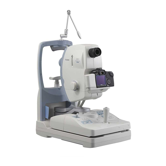
- Page 1 Digital Retinal Camera CX-1 Operation Manual Before using the instrument, be sure to read this manual thoroughly. Keep the manual where it is easily accessible.
- Page 2 7. In no event will Canon be liable for direct or indirect consequential damage arising out of the use of this product. Canon will not be liable for loss of image data due to any reason.
-
Page 3: Safety Information
This instrument conforms to IEC 60601-1-2:2001. For U.S.A. and Canada • When the CX-1 is going to be operated at a voltage of 240V in USA or Canada, be sure to con- nect the instrument to a center tapped voltage source. -
Page 4: General Safety Information
Safety Information Follow the safety instructions in this manual and all warnings and cautions printed on the warning labels. Ignoring such cautions or warnings while handling the product may result in injury or accident. Be sure to read and fully understand the manual before using this product. Keep this manual for future reference. -
Page 5: Safety Precautions
Also, when other equipment is going to be connected to the instrument using the WARNING connector for interface, be sure to check after the connection that leakage current is within the tolerable value. For details, please contact a Canon representative or distributor. Power Supply... - Page 6 WARNING Do not hold it by the digital camera or the face rest poles or other parts, as they may come off and result in injury. Do not hit or drop the instrument. The instrument may be damaged if it receives a...
-
Page 7: Maintenance And Inspection
When Problem Occurs Should any of the following occur, immediately turn OFF the power of each instrument, unplug the power cable from the AC outlet, and contact a Canon representative or distributor. • When there is smoke, an odd smell or abnormal sound. - Page 8 Safety Information System Use Do not place multiple portable socket-outlets on the floor. Otherwise, it may result in WARNING fire or electric shock. Do not connect an additional multiple portable socket-outlet or extension cord to the WARNING system. Otherwise, it may result in fire or electric shock. Do not connect instruments which are not specified as part of the system.
- Page 9 Safety Information Label on the Instrument The CX-1 has a label on it. The label contents and its position are indicated below.
-
Page 10: Table Of Contents
Components Digital Retinal Camera CX-1... 1 Digital camera ...1 Power cable (3 m, Non-shielded) ...1 * Plug shapes differ by power specifications. Chin rest paper ...100 Camera mount cap...1 Dust cover ...1 CD-ROM (Retinal imaging control software)...1 Optional Units Internal eye fixation target... - Page 11 Safety Information ...(1) Components ...(8) 1. Features ... 1 2. Notes for Using the Instrument... 2 3. Names of Parts... 4 3.1 Main Unit ...4 3.2 Operation Panel ...6 3.3 Observation Monitor and Viewfinder ...7 4. Preparation ... 8 4.1 Power Cable Connections ...8 4.2 Connecting to a Computer ...9 4.3 Carrying the Instrument ...10 5.
- Page 12 7.3.1 Objective Lens ... 44 7.3.2 Viewfinder ... 45 7.3.3 Forehead Rest ... 45 7.3.4 Retinal Camera and Digital Camera Outer Covers ... 46 7.4 Refilling the Chin Rest Paper ...47 7.5 Removing and Installing the Digital Camera ...48 7.5.1 Removing the Digital Camera ... 48 7.5.2 Installing the Digital Camera ...
-
Page 13: Digital Retinal Camera Cx-1
Small pupil photography function The CX-1 can photograph dilated pupils with a diameter of at least 5.1 mm in the mydriatic mode, with 50° of their field angle. It can photograph non-dilated pupils with the diameter of at least 4.3 mm in the non-mydriatic mode, with 45°... -
Page 14: Notes For Using The Instrument
2. Notes for Using the Instrument Digital camera • The digital camera installed on the Digital Retinal Camera CX-1 is designed for the CX-1. • The specifications differ from the typical commercially-available Canon digital cameras. It cannot be used for purposes other than observing and taking photographs of peoples’ eyes. Do not use the digital camera removing from the retinal camera body. -
Page 15: Chin Rest Paper
• If this product will be transported in an automobile or shipped a long distance, protective measures need to be taken for vibrations and shocks. Ask a Canon representative or distributor for more information. Others For U.S.A. Rx only-Caution: Federal law restricts this device to sale by or on the order of a licensed practitioner. -
Page 16: Names Of Parts
3. Names of Parts 3.1 Main Unit External eye fixation lamp (see page 17, Face rest Forehead rest (see page 45) Objective lens (see page 44) Objective lens cap Chin rest (see page 15) Diopter compensation lever (see page 34) Focus knob (see page 17, 27) Pan Tilt grip (see page 35) 10 Finger guard... - Page 17 12 Viewfinder (see page 7) 13 Digital camera (see page (8)) 14 Digital camera cover (see page 48) 15 Observation monitor (see page 7) 16 Digital camera power switch (see page 11) 17 Shutter release button (see page 18, 21,...
-
Page 18: Operation Panel
3. Names of Parts 3.2 Operation Panel Brightness adjuster (see page 16) Focus indicator switch/lamp (see page 33) ×2 switch/lamp (see page 33) Small pupil photography switch/lamp (see page 34) BA switch/lamp (see page 30) Flash intensity indicator (see page 19) Flash intensity switches (see page 19) TIMER/C switch/lamp (see page 22) Observation mode lamp... -
Page 19: Observation Monitor And Viewfinder
3.3 Observation Monitor and Viewfinder Observation monitor (with x1.3 magnification) Photography mode indication COLOR: Color (see page 14) RED FREE: Red free (see page 20) COBALT: Cobalt (see page 21) FLUO: Fluorescein angiography (see page 21) FAF: Fundus autofluorescence (see page 23) Focus indicator (see page 17) ×2 photography indicator (see page 33) Small pupil photography indicator... -
Page 20: Preparation
4. Preparation Please ask a Canon representative or distributor to perform installation of this instrument. 4.1 Power Cable Connections WARNING WARNING CAUTION CAUTION Check that the power switch of the retinal camera is set to the O position (OFF). Connect the power cable to the retinal camera. -
Page 21: Connecting To A Computer
• Cable with type AB connector plug supporting USB 2.0 Hi-Speed, maximum length of 3 meters For further details, contact a Canon representative or the distributor from which you purchased the unit. Note: When connecting the USB cable, pass it underneath the cables of the camera main unit. -
Page 22: Carrying The Instrument
See section 7.5.1 Removing the Digital Camera (page 48). Note: If this product will be transported in an automobile or shipped a long distance, protective measures need to be taken for vibrations and shocks. Ask a Canon representative or distributor for more information. -
Page 23: Dust Cover
For details on the control software operations, refer to the operation manual of the control software. Turn on the power switch of the digital camera. Set the power switch of the digital camera to Turn on the power of the retinal camera. -
Page 24: Move The Stage Unit To Get Started
5. Basic Photography 5.1.2 Move the Stage Unit to Get Started Press the stage unit lock button to release the lock. Grasp the operation lever, and pull the stage all the way to the right front, and then press the stage lock button to lock it in place. -
Page 25: Photography Flow
5.2 Photography Flow This instrument includes non-mydriatic and mydriatic observation modes. In each observation mode, photographs can be taken using color, red-free, cobalt, fluorescein angiography, or fundus autofluorescence. The observation monitor is used in non-mydriatic mode, and the viewfinder is used in mydriatic mode. -
Page 26: Non-Mydriatic Mode
5. Basic Photography 5.3 Non-Mydriatic Mode The Non-Mydriatic mode is designed for photographing the patient eye without using a mydriatic. To switch from the mydriatic mode to the non-mydriatic mode, hold down the observation mode switch for approx. 2 or more seconds. The observation mode lamp Non-Myd turns on. - Page 27 Align the height of the patient’s eye. Press the CHIN REST switches to adjust the chin rest up or down so that the patient’s eye is aligned with the height adjustment mark. Move the stage position. Do not put your fingers or hands between the sliding part and base of the stage unit or on the panning and tilting sliding parts.
- Page 28 5. Basic Photography Direction Height Side movement Forward/backward The right and left dots (working distance dots) appear sharpest when the retinal camera is at the optimum position. When the split lines are not visible Part of the split lines may not be visible if the pupil diameter is small. In this case, press the small pupil photography switch to turn on the small pupil photography function.
- Page 29 Determine the area to be photographed. Have the patient stare at the green internal eye fixation lamp. If necessary, press a FIX TARGET switch to move the internal eye fixation lamp to guide the patientís eye. If you press the blink switch, the internal eye fixation lamp blinks to make the lamp more noticeable to the patient and helps to guide the patient’s eye.
- Page 30 5. Basic Photography Take the image. Check that the photography ready lamp lights green. Check again that the working distance dots appear sharpest and the split lines form a single line, and then press the shutter release button. Concerning the photography ready lamp The ready status of the fundus camera is indicated by the color of the photography ready lamp.
- Page 31 Concerning the adjustment of the flash intensity (for color, red free, cobalt photography mode, and fluorescein angiography mode) The flash intensity is already set to the standard level for each photography mode. To adjust the intensity, press the flash intensity switches. Each time one of these switches is pressed, the intensity is increased or reduced by steps of 0.3.
-
Page 32: Red-Free Photography Mode
5. Basic Photography Concerning locking the stage unit When the stage unit lock button is pressed, the stage unit can be locked or unlocked in the following two places. Lock position Locked at center Lock at front right Turn off the power of the retinal camera. 5.3.2 Red-free Photography Mode Enter the study information into the computer. -
Page 33: Cobalt Photography Mode
5.3.3 Cobalt Photography Mode In this mode, photography using the exciter filter for fluorescein angiography is possible. Enter the study information into the computer. Select the cobalt photography mode. Press the COBALT switch. Or select the photography mode with the control software. - Page 34 5. Basic Photography Roughly determine the area to be photographed. Focus on the patient’s eye. Start the timer. Press the TIMER/C switch as soon as the fluorescein medium is injected. The buzzer sounds each second, the lamp lights brightly and the elapsed time is displayed in the control software.
-
Page 35: Fundus Autofluorescence Mode
5.3.5 Fundus Autofluorescence Mode Enter the study information into the computer. Select the fundus autofluorescence mode. Press the FAF switch. Or select the photography mode with the control software. The FAF lamp turns on. FAF is displayed on the observation monitor. Perform the procedure starting from step 3 in 5.3.1 Color Photography Mode (see page 14). -
Page 36: Mydriatic Mode
5. Basic Photography 5.4 Mydriatic Mode The Mydriatic mode is designed for photographing the patient’s eye that a mydriatic is applied. To switch from the non-mydriatic mode to the mydriatic mode, hold down the observation mode switch for approx. 2 or more seconds. The observation mode lamp Myd turns on. - Page 37 Align the height of the patient’s eye. Press the CHIN REST switches to adjust the chin rest up or down so that the patient’s eye is aligned with the height adjustment mark. Move the stage position. Do not put your fingers or hands between the sliding part and base of the stage unit or on the panning and tilting sliding parts.
- Page 38 5. Basic Photography Direction Height Side movement Forward/backward The right and left dots (working distance dots) appear sharpest when the retinal camera is at the optimum position. When the split lines are not visible Part of the split lines may not be visible if the pupil diameter is small. In this case, press the small pupil photography switch to turn on the small pupil photography function.
- Page 39 When it is difficult to guide a patient’s eye using the external eye fixation lamp Patients’ eyes can also be guided using the internal eye fixation target (sold separately). For details, contact a Canon representative or distributor. Focus on patient’s eye.
- Page 40 5. Basic Photography Take the image. Check that the photography ready lamp lights green. In a flare-free condition, check the focus again, and press the shutter release button. Concerning the photography ready lamp The ready status of the fundus camera is indicated by the color of the photography ready lamp. This status differs depending on the photography mode and image-taking conditions.
- Page 41 Review the image. The fundus images and study information are displayed in the control software. Check the images. To take images of the other eye, repeat steps 7 and the following. End the study. End the study with the control software. Lock the stage unit.
-
Page 42: Red-Free Photography Mode
5. Basic Photography 5.4.2 Red-free Photography Mode Enter the study information into the computer. Select the red-free photography mode. Press the RED FREE switch. Or select the photography mode with the control software. The RED FREE lamp turns on. Perform the procedure starting from step 3 in 5.4.1 Color Photography Mode (see page 24). 5.4.3 Cobalt Photography Mode Enter the study information into the computer. - Page 43 Focus on patient’s eye. Start the timer. Press the TIMER/C switch as soon as the fluorescein medium is injected. The buzzer sounds each second, the lamp lights brightly and the elapsed time is displayed in the control software. Take the image. In a flare-free condition, check the focus again, and press the shutter release button.
-
Page 44: Fundus Autofluorescence Mode
5. Basic Photography 5.4.5 Fundus Autofluorescence Mode Enter the study information into the computer. Select the fundus autofluorescence mode. Press the FAF switch. Or select the photography mode with the control software. The FAF lamp turns on. Perform the procedure starting from step 3 in 5.4.1 Color Photography Mode (see page 24). Concerning the adjustment of the flash intensity (for fundus autofluorescence mode) The flash intensity is already set to the standard level for each photography mode. -
Page 45: Photography Auxiliary Functions
6. Photography Auxiliary Functions 6.1 Using the Focus Indicator The focus indicator switch on the operation panel can be used to select whether to use the focus indicator or not. When the focus indicator is being used, the focus indicator lamp lights brightly. -
Page 46: Small Pupil Photography Function
6. Photography Auxiliary Functions 6.3 Small pupil photography function The small pupil photography function can be used in the color, red free or cobalt photography mode. To activate this function, press the small pupil photography switch on the operation panel. The small pupil photography lamp turns on brightly. -
Page 47: Panning Function And Tilting Function
6.5 Panning Function and Tilting Function 6.5.1 Panning Function This function is used to take photographs of peripheral areas in the side-to-side direction. First, turn the panning lock knob to the adjust the angle of the retinal camera in the side-to-side direction. -
Page 48: Camera Cover
6. Photography Auxiliary Functions 6.6 Using the External Monitor The image on the observation monitor can be viewed on an external monitor. Please ask your Canon representative or distributor about which external monitors can be used. Before connecting or disconnecting the cable, turn off the power for the retinal camera. - Page 49 Turn on the external monitor, and get the input selected on the monitor. Turn on the power for the retinal camera and digital camera. The image is displayed on the connected external monitor (No image is displayed on the digital camera observation monitor).
-
Page 50: Daily Inspection And Maintenance
In order to ensure that the instrument is used safely and normally, please be sure to inspect the instrument before use. If the inspection finds a fault, and you are unable to correct the problem, please contact a Canon representative or distributor. -
Page 51: Before Turning On The Power
7. Daily Inspection and Maintenance Result Month Month Month Contact a Canon representative or Pass/ Pass/ Pass/ distributor if there is any Fail Fail Fail problem. -
Page 52: Turning On The Power
Check that the chin rest moves smoothly up and down when the CHIN REST switch is pressed. Result Month Month Month Contact a Canon representative or Pass/ Pass/ Pass/ distributor if there is any Fail Fail Fail problem. Result... -
Page 53: External Eye Fixation Lamp
If performing the remedy still does not fix the problem, or the warning is still displayed, turn OFF the power, and contact a Canon representative or distributor. Please be sure to describe the problem or warning message in detail. - Page 54 -10 to +15 D. -42- Remedy Lower the observation light intensity. Perform positioning (see page 15). Contact a Canon representative or distributor. Reduce the brightness for observation. Perform positioning. Press the focus indicator switch to display the split bar.
- Page 55 Clean the lens (see page 44). Perform a self-cleaning (see page 52). Note: The imaging sensor is very sensitive. Contact a Canon representative or distributor for cleaning it. Clean the lens (see page 44). Instruct the patient to open his or her eye wider.
-
Page 56: Cleaning And Disinfection
Note: Do not let the tip of a blower touch the objective lens. Use the procedure below to clean the objective lens when it is dirty. Please order the lens cleaning paper, lens cleaner, and blower from a Canon representative or distributor. Turn ON the power of the retinal camera. -
Page 57: Viewfinder
Wipe off the objective lens. Gently wipe the lens with Canon-designated lens cleaning paper that has been slightly wet with the Canon-designated lens cleaner. Starting from the center of the lens, wipe the lens in increasingly larger spirals toward the circumference. -
Page 58: Retinal Camera And Digital Camera Outer Covers
7. Daily Inspection and Maintenance 7.3.4 Retinal Camera and Digital Camera Outer Covers WARNING Note: Do not clean the cover of the instrument with lens cleaner. The cover of the instrument could be damaged. Use the procedure below to clean the cover when it is dirty. -
Page 59: Refilling The Chin Rest Paper
Note: The chin rest paper is a consumable product (sold separately). To purchase the chin rest paper, please contact a Canon representative or distributor. Pull out the chin rest right and left holding pins. -
Page 60: Removing And Installing The Digital Camera
Note: Do not touch the lens part of the main unit and the mirror part of the digital camera when attaching and detaching the digital camera from the retinal camera body. If any dirt, fingerprints, dust, and other foreign objects attaches to the lens or mirror part, you cannot take a good image. - Page 61 While pressing down on the lens unlock button of the digital camera counterclockwise so that the camera mount index I on the top of the digital camera is aligned with the seam of the cover of the retinal camera body...
-
Page 62: Body Cap
Attach the mount cap to the retinal camera mount. Also attach the body cap to the digital camera. Note: The digital retinal camera CX-1 is already installed with an digital camera for this instrument. Please take careful note of the following points if the digital camera must be removed or installed. - Page 63 Hold the knob of the mount lock lever, and push down the lever to the LOCK position Turn the digital camera clockwise until it clicks into place Check that the digital camera is firmly secured in place. 7. Daily Inspection and Maintenance Seam of cover is aligned with the cover...
-
Page 64: Cleaning The Digital Camera (Imaging Sensor)
7.5.3 Cleaning the Digital Camera (imaging sensor) In this digital camera, a self-cleaning sensor unit is activated when the power switch is set to the ON or position and to the OFF position for automatically removing dust and other substances that are adhering to the imaging sensor front surface. -
Page 65: Main Specifications And Performance
30° to the right and left 15° up and 10° down AC 100 V to 240 V, 50/60 Hz, 8 A to 4 A 320 (W) × 531 (D) × 577 (H) mm 26 kg (including the digital camera (0.8 kg)) -53-... -
Page 66: Functions In The Observation And Photography Modes
8. Main Specifications and Performance 8.2 Functions in the Observation and Photography Modes The following table shows the availability of functions when each of observation modes is used with each photography mode. Available options are indicated with the check mark “ ”. Unavailable options are indicated with “N/A.”... -
Page 67: Guidance And Manufacturer's Declaration For Emc Directive
8.3 Guidance and Manufacturer’s Declaration for EMC Directive Electromagnetic Emissions The CX-1 is intended for use in the electromagnetic environment specified below. The customer or the user of the CX-1 should assure that it is used in such an environment. Emission Test... - Page 68 8. Main Specifications and Performance Electromagnetic Immunity The CX-1 is intended for use in the electromagnetic environment specified below. The customer or the user of the CX-1 should assure that it is used in such an environment. Immunity Test Electrostatic...
- Page 69 RF transmitters, an electromagnetic site survey should be considered. If the measured field strength in the location in which the CX-1 is used exceeds the applicable RF compliance level above, the CX-1 should be observed to verify normal operation.
- Page 70 AC Power Cable USB Cable USB Cable NOTE 2: Do not install the CX-1 adjacent to or stacked with other electric/electronic equipment. NOTE 3: Essential Performance (against Electromagnetric Disturbances) • No unintentional raise/lower movements of Chin Rest shall occur. • No unintentional flashing shall occur.
-
Page 71: Service Information
9. Service Information Repair If problem cannot be solved even after taking the measures indicated in Section 7, contact a Canon representative or distributor for repair. When requesting repair, please provide us with the following information by referring to the rating label on the main unit. - Page 74 CANON INC. Medical Equipment Group 30-2, Shimomaruko 3-chome, Ohta-ku, Tokyo, Japan Telephone: (81)-3-3758-2111 CANON U.S.A., INC. CANON MEDICAL SYSTEMS Eye Care Systems Department 15975 Alton Parkway, Irvine, CA 92618, U.S.A. Telephone: (1)-949-753-4000 CANON EUROPA N.V. Medical Products Division Bovenkerkerweg 59-61, 1185 XB Amstelveen, The Netherlands Telephone: (31)-20-545-8926 CANON (CHINA) CO., LTD.