Table of Contents
Advertisement
Questo manuale d'istruzione è fornito da trovaprezzi.it. Scopri tutte le offerte per
C1000-8T-2G-L
o cerca il tuo prodotto tra le
Cisco Catalyst 1000 Series 8-Port and 16-Port Switch Hardware
Installation Guide
First Published: 2019-12-25
Americas Headquarters
Cisco Systems, Inc.
170 West Tasman Drive
San Jose, CA 95134-1706
USA
http://www.cisco.com
Tel: 408 526-4000
800 553-NETS (6387)
Fax: 408 527-0883
migliori offerte di Switch
Cisco Catalyst 1000
Advertisement
Table of Contents

Related Manuals for Cisco C1000-8T-2G-L


Summary of Contents for Cisco C1000-8T-2G-L
- Page 1 Questo manuale d’istruzione è fornito da trovaprezzi.it. Scopri tutte le offerte per Cisco Catalyst 1000 C1000-8T-2G-L o cerca il tuo prodotto tra le migliori offerte di Switch Cisco Catalyst 1000 Series 8-Port and 16-Port Switch Hardware Installation Guide First Published: 2019-12-25 Americas Headquarters Cisco Systems, Inc.
-
Page 2: Table Of Contents
Port LEDs Rear Panel Internal Power Supply Security Slot Network Configurations C H A P T E R 2 Switch Installation Safety Warnings Box Contents Tools and Equipment Installation Guidelines Cisco Catalyst 1000 Series 8-Port and 16-Port Switch Hardware Installation Guide... - Page 3 Switch Connections Bad or Damaged Cable Ethernet and Fiber-Optic Cables Link Status 10/100/1000 Port Connections 10/100/1000 PoE+ Port Connections SFP Module Interface Settings Ping End Device Spanning Tree Loops Cisco Catalyst 1000 Series 8-Port and 16-Port Switch Hardware Installation Guide...
- Page 4 Installing the Cisco Microsoft Windows XP USB Driver Installing the Cisco Microsoft Windows 2000 USB Driver Installing the Cisco Microsoft Windows 7 USB Driver Uninstalling the Cisco Microsoft Windows USB Driver Cisco Catalyst 1000 Series 8-Port and 16-Port Switch Hardware Installation Guide...
- Page 5 Contents Uninstalling the Cisco Microsoft Windows XP and 2000 USB Driver Uninstalling the Cisco Microsoft Windows 7 USB Driver Cisco Catalyst 1000 Series 8-Port and 16-Port Switch Hardware Installation Guide...
- Page 6 Contents Cisco Catalyst 1000 Series 8-Port and 16-Port Switch Hardware Installation Guide...
-
Page 7: Preface
[x | y] Optional alternative keywords are grouped in brackets and separated by vertical bars. {x | y} Required alternative keywords are grouped in braces and separated by vertical bars. Cisco Catalyst 1000 Series 8-Port and 16-Port Switch Hardware Installation Guide... -
Page 8: Related Documentation
Statement 1071 SAVE THESE INSTRUCTIONS Related Documentation • Cisco SFP modules documentation, including compatibility matrixes, located at: Cisco Catalyst 1000 Series 8-Port and 16-Port Switch Hardware Installation Guide viii... -
Page 9: Obtaining Documentation And Submitting A Service Request
Obtaining Documentation and Submitting a Service Request For information on obtaining documentation, submitting a service request, and gathering additional information, see the monthly What's New in Cisco Product Documentation, which also lists all new and revised Cisco technical documentation, at: http://www.cisco.com/c/en/us/td/docs/general/whatsnew/whatsnew.html... - Page 10 Preface Obtaining Documentation and Submitting a Service Request Cisco Catalyst 1000 Series 8-Port and 16-Port Switch Hardware Installation Guide...
-
Page 11: Product Overview
C H A P T E R Product Overview The Cisco Catalyst 1000 Series switches are fixed-configuration, Gigabit Ethernet switches that provide entry-level enterprise-class Layer 2 access for branch offices, conventional workspace, and out-of-wiring closet applications. Cisco Catalyst 1000 Series switches provide support for the following features: •... -
Page 12: Front Panel
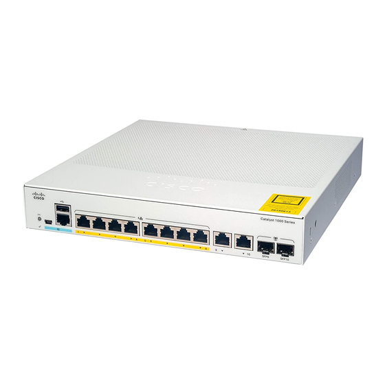
16 10/100/1000 PoE+ ports (PoE budget of 240W); 2 1-Gigabit SFP module uplink slots. Front Panel This section describes the front panel components of an 8-port and 16-port Cisco Catalyst 1000 switch. • 8 or 16 downlink Ethernet ports of one of these types: • 10/100/1000 •... - Page 13 Product Overview Front Panel Figure 1: Front Panel of an 8-Port Cisco Catalyst C1000 PoE Switch Reset button RJ-45 Console Port System LEDs 8 10/100/1000 PoE+ ports USB mini-Type B Combo ports (2 GE (console) port Copper ports and 2 SFP...
-
Page 14: Poe Ports
The ports provide PoE support for devices compliant with IEEE 802.3af and IEEE 802.3at and also provide PoE support for Cisco IP Phones and Cisco Aironet Access Points. The PoE switch ports are Power Source equipment (PSE) capable and source power to PD devices connected to the downlink ports. A switch can source POE power of up to 30.8W per port. -
Page 15: Console Ports
The USB mini-Type B console port is not supported on the Cisco Catalyst 1000 Fast Ethernet Series Switches. If you use the USB mini-Type B console port, the Cisco Windows USB device driver must be installed on any PC connected to the console port (for operation with Microsoft Windows). Mac OS X or Linux do not require special drivers. -
Page 16: Leds
Product Overview LEDs Table 2: Port mapping for Cisco Catalyst 1000 8-Port Switch models 1-GigabitEthernet ports GigabitEthernet1/0/9 GigabitEthernet1/0/10 Table 3: Port mapping for Cisco Catalyst 1000 16-Port Switch models 1-GigabitEthernet ports GigabitEthernet1/0/17 GigabitEthernet1/0/18 LEDs You can use the switch system and port LEDs to monitor switch activity and performance. -
Page 17: System Led
Product Overview System LED Figure 4: System LED for a Cisco Catalyst 1000 Series Switch SYST LED (system) Port LEDs System LED Color System Status System is not powered on. Green System is operating normally. Amber System is receiving power but is not operating properly. -
Page 18: Port Leds
• Heat sink fins (PoE models only) Figure 5: Rear Panel of a Non-PoE Switch Security Slot A loop (for the optional power cord retainer) An AC power connector Cisco Catalyst 1000 Series 8-Port and 16-Port Switch Hardware Installation Guide... - Page 19 A loop (for the optional power cord retainer) Figure 7: Rear Panel of an Externally Powered Switch Security Slot A loop (for the optional power cord retainer) A DC power connector Cisco Catalyst 1000 Series 8-Port and 16-Port Switch Hardware Installation Guide...
-
Page 20: Internal Power Supply
See the switch software configuration guide for network configuration concepts and examples of using the switch to create dedicated network segments and interconnecting the segments through Fast Ethernet and Gigabit Ethernet connections. Cisco Catalyst 1000 Series 8-Port and 16-Port Switch Hardware Installation Guide... -
Page 21: Switch Installation
Before working on equipment that is connected to power lines, remove jewelry (including rings, necklaces, and watches). Metal objects will heat up when connected to power and ground and can cause serious burns or weld the metal object to the terminals. Statement 43 Cisco Catalyst 1000 Series 8-Port and 16-Port Switch Hardware Installation Guide... - Page 22 Do not work on the system or connect or disconnect cables during periods of lightning activity. Statement 1001 Warning Read the installation instructions before connecting the system to the power source. Statement 1004 Cisco Catalyst 1000 Series 8-Port and 16-Port Switch Hardware Installation Guide...
- Page 23 Ultimate disposal of this product should be handled according to all national laws and regulations. Statement 1040 Warning When installing or replacing the unit, the ground connection must always be made first and disconnected last. Statement 1046 Cisco Catalyst 1000 Series 8-Port and 16-Port Switch Hardware Installation Guide...
- Page 24 A restricted access area can be accessed only through the use of a special tool, lock and key or other means of security. Statement 1072 Cisco Catalyst 1000 Series 8-Port and 16-Port Switch Hardware Installation Guide...
-
Page 25: Box Contents
To prevent airflow restriction, allow clearance around the ventilation openings to be at least: 3 inches (7.6 cm). Statement 1076 Warning Hot surface. Statement 1079 Box Contents This section lists the contents of the shipping box for an 8-port and 16-port Cisco Catalyst 1000 switch. Cisco Catalyst 1000 Series 8-Port and 16-Port Switch Hardware Installation Guide... - Page 26 (Optional) DIN rail mount (only with Cisco Catalyst 1000 16-port switch models) This section lists the contents of the shipping box for an externally powered 8-port and 16-port Cisco Catalyst 1000 switch. Cisco Catalyst 1000 Series 8-Port and 16-Port Switch Hardware Installation Guide...
- Page 27 Switch Installation Box Contents Figure 10: Box Contents of an Externally Powered 8-Port and 16-Port Cisco Catalyst 1000 Switch Externally powered 8-port or 16-port (Optional) Power cord retainer Cisco Catalyst 1000 switch AC power cord (Optional) Cable guard Cisco Catalyst 1000 Series 8-Port and 16-Port Switch Hardware Installation Guide...
-
Page 28: Tools And Equipment
• Allow at least 1.75 in. (4 cm) of clearance from the top cover, if you are installing the switch in upright position. • Allow at least 3 in. (7.6 cm) of clearance from the top cover, if you are installing the switch. Cisco Catalyst 1000 Series 8-Port and 16-Port Switch Hardware Installation Guide... -
Page 29: Verifying Switch Operation
After a successful POST, unplug the power cord from the switch and install the switch on a wall, on a table, or on a shelf. Warning Attach only the following Cisco external power system to the switch: Cisco XPS 2200 Statement 387 Mounting the Switch Mounting on a Desk or Shelf Without Mounting Screws... -
Page 30: On A Desk, Shelf, Or Wall (With Mounting Screws)
Step 6 Remove the screw template from the desk or shelf. Step 7 Place the switch onto the mounting screws, and slide it forward until it locks in place. Cisco Catalyst 1000 Series 8-Port and 16-Port Switch Hardware Installation Guide... -
Page 31: Wall-Mounting
For the best support of the switch and cables, make sure that you attach the switch securely to a wall stud or to a firmly attached plywood mounting backboard Cisco Catalyst 1000 Series 8-Port and 16-Port Switch Hardware Installation Guide... - Page 32 Figure 13: Installing the Mounting Screws on the Wall Step 7 Remove the screw template from the wall. Step 8 Place the switch onto the mounting screws, and slide it down until it locks in place. Cisco Catalyst 1000 Series 8-Port and 16-Port Switch Hardware Installation Guide...
-
Page 33: In A Rack
• If the rack is provided with stabilizing devices, install the stabilizers before mounting or servicing the unit in the rack. Statement 1006 Cisco Catalyst 1000 Series 8-Port and 16-Port Switch Hardware Installation Guide... - Page 34 Warning To prevent airflow restriction, allow clearance around the ventilation openings to be at least: 3 in. (7.6 cm) Statement 1076 Cisco Catalyst 1000 Series 8-Port and 16-Port Switch Hardware Installation Guide...
-
Page 35: On A Din Rail
Figure 16: Mounting the Switch in a Rack On a DIN Rail The DIN-mount kit (part number CMPCT-DIN-MNT=) is optional only with Cisco Catalyst 1000 16-port switch models. You can order it when you order your switch. The DIN-mount kit contains: •... - Page 36 Figure 17: Placing the Switch on the DIN-Mount Tray Switch DIN rail mount Step 2 Use the two number-10 Phillips pan-head screws to secure the DIN rail mount to the switch. Cisco Catalyst 1000 Series 8-Port and 16-Port Switch Hardware Installation Guide...
-
Page 37: Mounting The Switch On A Din Rail
Position the switch directly in front of the DIN rail, making sure that the top of the DIN rail mount clip hooks over the top of the DIN rail. Cisco Catalyst 1000 Series 8-Port and 16-Port Switch Hardware Installation Guide... -
Page 38: Removing The Switch From A Din Rail
Ensure that power is removed from the switch, and disconnect all cables and connectors from the front panel of the switch. Step 2 Pull down on the DIN rail mount release tabs. As the clips release, lift the bottom of the switch. Cisco Catalyst 1000 Series 8-Port and 16-Port Switch Hardware Installation Guide... -
Page 39: Installing The Power Cord Retainer (Optional)
Step 1 Choose the sleeve size of the power cord retainer based on the thickness of the cord. The smaller sleeve can be snapped off and used for thin cords. Cisco Catalyst 1000 Series 8-Port and 16-Port Switch Hardware Installation Guide... - Page 40 Sleeve for thinner power cords Power cord retainer Loop Step 3 Slide the retainer through the first latch. Figure 22: Sliding the Retainer Through the Latch AC power cord Latch Cisco Catalyst 1000 Series 8-Port and 16-Port Switch Hardware Installation Guide...
- Page 41 Detach the sleeve, and slide it over the power cord. Figure 24: Sleeve Around the Power Cord Smaller sleeve for thin AC power cord power cords Step 6 Secure the AC power cord by pressing on the retainer. Cisco Catalyst 1000 Series 8-Port and 16-Port Switch Hardware Installation Guide...
-
Page 42: Installing The Cable Guard (Optional)
• Two washers Procedure Step 1 (Optional) Attach the supplied washers before you install the cable guard. This is only required if you are not installing the wall-mount brackets. Note Cisco Catalyst 1000 Series 8-Port and 16-Port Switch Hardware Installation Guide... - Page 43 Two number-10 Phillips pan-head screws Cable Guard Step 3 Loosen the number-10 Phillips pan-head screws, slide the cable guide out, and pivot it upwards so that you can install the cables. Cisco Catalyst 1000 Series 8-Port and 16-Port Switch Hardware Installation Guide...
- Page 44 Step 5 Guide the connected cables through the slots in the front of the cable guard. Slide the cable guide in as shown in the following figure. Tighten the screws. Cisco Catalyst 1000 Series 8-Port and 16-Port Switch Hardware Installation Guide...
-
Page 45: Installing Sfp Modules
Installing SFP Modules See the switch release notes on Cisco.com for the list of supported SFP modules. Use only Cisco SFP modules on the switch. Each Cisco module has an internal serial EEPROM that is encoded with security information. -
Page 46: Installing An Sfp Module
Step 5 If the module has a bale-clasp latch, close it. Step 6 For fiber-optic SFP modules, remove the dust plugs and save. Step 7 Connect the SFP cables. Cisco Catalyst 1000 Series 8-Port and 16-Port Switch Hardware Installation Guide... -
Page 47: Removing An Sfp Module
The ports provide PoE support for devices compliant with IEEE 802.3af and 802.3at (PoE+), and also provide Cisco prestandard PoE support for Cisco IP Phones and Cisco Aironet Access Points. Cisco Catalyst 1000 Series 8-Port and 16-Port Switch Hardware Installation Guide... - Page 48 On a per-port basis, you can control whether or not a port automatically provides power when an IP phone or an access point is connected. To access an advanced PoE planning tool, use the Cisco Power Calculator available on Cisco.com at this URL: http://tools.cisco.com/cpc/launch.jsp...
-
Page 49: 10/100/1000 Ethernet Port Connections
Switch to computer or server Switch to router Switch to IP phone 100BASE-TX and 1000BASE-T traffic requires twisted four-pair, Category 5 or higher. 10BASE-T traffic can use Category 3 cable or higher. Cisco Catalyst 1000 Series 8-Port and 16-Port Switch Hardware Installation Guide... - Page 50 Switch Installation Auto-MDIX Connections Cisco Catalyst 1000 Series 8-Port and 16-Port Switch Hardware Installation Guide...
-
Page 51: Troubleshooting
You can also get statistics from Device Manager, from the CLI, or from an SNMP workstation. Switch POST Results POST failures are usually fatal. Contact your Cisco technical support representative if your switch does not pass POST. System LEDs If you have physical access to the switch, look at the port LEDs for troubleshooting information about the switch. -
Page 52: Ethernet And Fiber-Optic Cables
• Verify that there is sufficient PoE power budget to provide power to the attached device. Use the show power inline global configuration command to check on the available PoE power budget. Cisco Catalyst 1000 Series 8-Port and 16-Port Switch Hardware Installation Guide... -
Page 53: Sfp Module
PoE fault. SFP Module Use only Cisco SFP modules in the switch. Each Cisco module has an internal serial EEPROM that is encoded with security information. This encoding provides a way for Cisco to identify and validate that the module meets the requirements for the switch. -
Page 54: Switch Performance
Finding the Switch Serial Number If you contact Cisco Technical Assistance, you need to know the switch serial number. You can also use the show version privileged EXEC command to see the switch serial number. - Page 55 Troubleshooting Finding the Switch Serial Number Figure 33: Serial Number Location on an 8-Port Cisco Catalyst 1000 Series Switch Product label Serial number Cisco Catalyst 1000 Series 8-Port and 16-Port Switch Hardware Installation Guide...
- Page 56 Troubleshooting Finding the Switch Serial Number Figure 34: Serial Number Location on a 16-Port Cisco Catalyst 1000 Series Switch NAL label Product label 4 in 1 label (includes PID number, Serial number, MAC address, and CLEI code) Cisco Catalyst 1000 Series 8-Port and 16-Port Switch Hardware Installation Guide...
-
Page 57: Technical Specifications
• 3.92 lbs (1.78 kg) (C1000-16T-2G-L) • 3.13 lbs (1.42 kg) (C1000-16T-E-2G-L) • 5.24 lbs (2.38 kg) (C1000-16P-2G-L) • 3.13 lbs (1.42 kg) (C1000-16P-E-2G-L) • 5.48 lbs (2.49 kg) (C1000-16FP-2G-L) Cisco Catalyst 1000 Series 8-Port and 16-Port Switch Hardware Installation Guide... -
Page 58: Environmental Specifications
Minimum ambient temperature for cold start is 32°F (0°C) Note When using the Cisco Catalyst 1000 series 8-port and 16-port switches with GLC-BX-U or GLC-BX-D SFP module, the thermal limitations are as follows: • Up to 5,000 ft (1524 m), the operation temperature should not exceed 113°F (45°C). -
Page 59: Power Requirements
Wattage for BTU/hr C1000-8T-2G-L 14.26 16.249 C1000-8T-E-2G-L 16.78 C1000-8P-2G-L 12.19 80.24 89.71 C1000-8P-E-2G-L 15.71 67.82 87.78 C1000-8FP-2G-L 14.52 138.15 156.15 C1000-8FP-E-2G-L 15.7 141.16 153.35 C1000-16T-2G-L 16.68 18.89 C1000-16T-E-2G-L 16.68 18.92 Cisco Catalyst 1000 Series 8-Port and 16-Port Switch Hardware Installation Guide... - Page 60 Switch Model Consumption Consumption with Available PoE Maximum Power without PoE (Watts) PoE (Watts) Wattage for BTU/hr C1000-16P-2G-L 16.92 136.92 40.7 C1000-16P-E-2G-L 16.32 136.32 36.68 C1000-16FP-2G-L 16.8 256.8 54.4 Cisco Catalyst 1000 Series 8-Port and 16-Port Switch Hardware Installation Guide...
-
Page 61: Connector And Cable Specifications
Connector Specifications 10/100/1000 Ports (Including PoE) All 10/100/1000 ports use standard RJ-45 connectors and Ethernet pinouts. Figure 35: 10/100/1000 Port Pinouts SFP Module Connectors Figure 36: Duplex LC Cable Connector Cisco Catalyst 1000 Series 8-Port and 16-Port Switch Hardware Installation Guide... -
Page 62: Cables And Adapters
Each port must match the wavelength specifications on the other end of the cable, and the cable must not exceed the stipulated cable length. Copper 1000BASE-T SFP module transceivers use standard four twisted-pair, Category 5 cable at lengths up to 328 feet (100 meters). Cisco Catalyst 1000 Series 8-Port and 16-Port Switch Hardware Installation Guide... -
Page 63: Cable Pinouts
The wire connected to the pin on the outside of the left plug should be a different color from the wire connected to the pin on the inside of the right plug. Cisco Catalyst 1000 Series 8-Port and 16-Port Switch Hardware Installation Guide... -
Page 64: Console Port Adapter Pinouts
RJ-45-to-DB-9 Terminal Adapter Console Device Signal DB-9 Pin Signal Table 7: Console Port Signaling with a DB-25 Adapter Switch Console Port (DTE) RJ-45-to-DB-25 Terminal Adapter Console Device Signal DB-25 Pin Signal Cisco Catalyst 1000 Series 8-Port and 16-Port Switch Hardware Installation Guide... - Page 65 Connector and Cable Specifications Connector and Cable Specifications Switch Console Port (DTE) RJ-45-to-DB-25 Terminal Adapter Console Device Signal DB-25 Pin Signal Cisco Catalyst 1000 Series 8-Port and 16-Port Switch Hardware Installation Guide...
- Page 66 Connector and Cable Specifications Connector and Cable Specifications Cisco Catalyst 1000 Series 8-Port and 16-Port Switch Hardware Installation Guide...
-
Page 67: Configuring The Switch
If your device supports Bluetooth, it loads with the initial setup tasks preconfigured. Connect your PC to the device using Bluetooth. In your Web browser, enter the IP address 172.16.0.1. Enter the following default credentials: username: cisco, password: cisco and press Enter. Cisco Catalyst 1000 Series 8-Port and 16-Port Switch Hardware Installation Guide... - Page 68 Confirm that the STAT LED is solid green. This indicates that POST is complete. If the STAT LED turns amber, the device failed POST. Reconnect the AC power cord to the AC power connector of your device and to a grounded AC outlet. If the STAT LED still does not turn green, contact your Cisco representative or retailer.
-
Page 69: Completing The Configuration Setup Wizard
To log on to the device using an Internet browser on your PC, type the IP address 10.0.0.1 or 10.0.0.3 in the address bar of your Internet browser and press Enter. Step 8 Type the following default credentials: username: cisco, password: cisco and press Enter. The Configuration Setup wizard is displayed. Click Go to Wizard. Completing the Configuration Setup Wizard Completing the Configuration Setup Wizard enables you to set up your device with the minimum configuration required to enable traffic to pass through the network. -
Page 70: Connecting The Rj-45 Console Port
Configure the baud rate and character format of the PC or terminal to match the console port default characteristics: • 9600 baud • 8 data bits • 1 stop bit • No parity • None (flow control) Cisco Catalyst 1000 Series 8-Port and 16-Port Switch Hardware Installation Guide... -
Page 71: Installing The Cisco Microsoft Windows Usb Device Driver
Installing the Cisco Microsoft Windows XP USB Driver Procedure Step 1 Obtain the Cisco USB console driver file from the Cisco.com web site and unzip it. You can download the driver file from the Cisco.com site for downloading the switch software. Note Step 2 If using 32-bit Windows XP, double-click the setup.exe file in the Windows_32 folder. -
Page 72: Installing The Cisco Microsoft Windows 7 Usb Driver
Installing the Cisco Microsoft Windows 7 USB Driver Procedure Step 1 Obtain the Cisco USB console driver file from the Cisco.com web site and unzip it. You can download the driver file from the Cisco.com site for downloading the switch software. Note Step 2 If using 32-bit Windows 7, double-click the setup.exe file in the Windows_32 folder. - Page 73 When the Remove the Program window appears, click Remove. If a User Account Control warning appears, click Allow - I trust this program to proceed. Note Step 5 When the InstallShield Wizard Completed window appears, click Finish. Cisco Catalyst 1000 Series 8-Port and 16-Port Switch Hardware Installation Guide...
- Page 74 Configuring the Switch Uninstalling the Cisco Microsoft Windows 7 USB Driver Cisco Catalyst 1000 Series 8-Port and 16-Port Switch Hardware Installation Guide...
- Page 75 Cisco has more than 200 offices worldwide. Addresses and phone numbers are listed on the Cisco website at www.cisco.com/go/offices. Cisco and the Cisco logo are trademarks or registered trademarks of Cisco and/or its affiliates in the U.S. and other countries. To view a list of Cisco trademarks, go to this URL: https://www.cisco.com/c/en/us/about/legal/trademarks.html.