Table of Contents
Advertisement
Quick Links
Advertisement
Table of Contents

Related Manuals for Kanomax 6824


Summary of Contents for Kanomax 6824
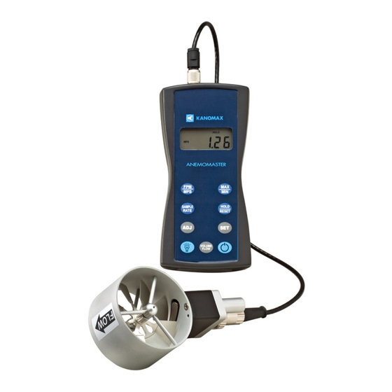
- Page 1 PO Box 372 Fax: (973) 786-7586 Andover, NJ 07821 USA info@kanomax-usa.com Model 6824 ™ THERMO-ANEMOMETER User Manual 6824 ™ User Manual, PN 10283 Kanomax USA, Inc Rev 1.0, 30-July-2021 www.kanomax-usa.com Page 1 of 28 Copyright © 2021, Kanomax USA, Inc.
- Page 2 You now own one of the most accurate, dependable, and highly regarded airflow measurement instruments available today. Kanomax’ s model 6824 digital thermo-anemometer is a versatile instrument for measuring air velocity and temperature in various applications such as HVAC, aerospace development, industrial process airflow, and fluids research.
-
Page 3: Warranty
Andover, New Jersey 07821 Please include a note with name, address, telephone number and description of the problem. Although we provide assistance on Kanomax products both personally and through our literature, it is still the total responsibility of the customer to determine the suitability of the product for use in their application. -
Page 4: Important Safety Information
However, there is no guarantee that interference will not occur in a particular situation. 6824 ™ User Manual, PN 10283 Kanomax USA, Inc Rev 1.0, 30-July-2021 www.kanomax-usa.com Page 4 of 28 Copyright © 2021, Kanomax USA, Inc. - Page 5 WEEE – Waste Electrical and Electronic Equipment 2002/96/EC Kanomax asks that all our products to be recycled at the end of their current use, to comply with local waste requirements. Kanomax supports local Waste Electrical and Electronic Equipment (WEEE) directives where they are in operation.
- Page 6 Dropping the instrument or the probe may cause damage or malfunction to the instrument and may change the calibration data. We recommend sending it in immediately to be checked. 6824 ™ User Manual, PN 10283 Kanomax USA, Inc Rev 1.0, 30-July-2021 www.kanomax-usa.com Page 6 of 28 Copyright © 2021, Kanomax USA, Inc.
- Page 7 When storing or shipping the instrument, the manufacturer recommends disconnecting the cable(s) and returning it to the original carrying case. 6824 ™ User Manual, PN 10283 Kanomax USA, Inc Rev 1.0, 30-July-2021 www.kanomax-usa.com Page 7 of 28 Copyright © 2021, Kanomax USA, Inc.
-
Page 8: Section 1 - Specifications
Approx. 150 hours, without backlight Battery check: Automatic low battery display Display: 0.5” LCD, 4 digits, with LED backlight 6824 ™ User Manual, PN 10283 Kanomax USA, Inc Rev 1.0, 30-July-2021 www.kanomax-usa.com Page 8 of 28 Copyright © 2021, Kanomax USA, Inc. - Page 9 (3) Size AA 1.5V alkaline batteries (installed in instrument) (1) Hard-shell carrying case with foam liner (1) 6824 operation manual Dimensions INSTRUMENT 6824 ™ User Manual, PN 10283 Kanomax USA, Inc Rev 1.0, 30-July-2021 www.kanomax-usa.com Page 9 of 28 Copyright © 2021, Kanomax USA, Inc.
- Page 10 Phone: 1-800-247-8887 PO Box 372 Fax: (973) 786-7586 Andover, NJ 07821 USA info@kanomax-usa.com APT275 PROBE APT100 PROBE 6824 User Manual, PN 10283 Kanomax USA, Inc ™ Rev 1.0, 30-July-2021 www.kanomax-usa.com Page 10 of 28 Copyright © 2021, Kanomax USA, Inc.
-
Page 11: Section 2 - Switch Functions
3 seconds. The LCD will flash. The backlight is now switched on permanently. To switch the backlight off, press the backlight key again. 6824 ™ User Manual, PN 10283 Kanomax USA, Inc Rev 1.0, 30-July-2021 www.kanomax-usa.com Page 11 of 28 Copyright © 2021, Kanomax USA, Inc. - Page 12 An average value of airspeed measurements during the preceding 16 seconds is displayed. Note: The sample rate for temperature readings is always 2 seconds. 6824 ™ User Manual, PN 10283 Kanomax USA, Inc Rev 1.0, 30-July-2021 www.kanomax-usa.com Page 12 of 28 Copyright © 2021, Kanomax USA, Inc.
- Page 13 HOLD/RESET key is pressed while in MAX/MIN mode, new readings are no longer recorded. To return to MAX/MIN mode, press the HOLD/RESET key again. 6824 ™ User Manual, PN 10283 Kanomax USA, Inc Rev 1.0, 30-July-2021 www.kanomax-usa.com Page 13 of 28 Copyright © 2021, Kanomax USA, Inc.
-
Page 14: Appendix A - Lcd Display Symbols
(973) 786-7586 Andover, NJ 07821 USA info@kanomax-usa.com APPENDIX A – LCD DISPLAY SYMBOLS APPENDIX B – BATTERY REPLACEMENT 6824 ™ User Manual, PN 10283 Kanomax USA, Inc Rev 1.0, 30-July-2021 www.kanomax-usa.com Page 14 of 28 Copyright © 2021, Kanomax USA, Inc. -
Page 15: Appendix C - Airflow Volume Calculations
Step 3: Volume flow = Air Velocity x Area, therefore, Volume flow rate = 450 FPM x 2 sq ft. = 900 CFM. 6824 ™ User Manual, PN 10283 Kanomax USA, Inc Rev 1.0, 30-July-2021 www.kanomax-usa.com Page 15 of 28 Copyright © 2021, Kanomax USA, Inc. -
Page 16: Appendix D - Analog Outputs (If Equipped)
20. the instrument is measuring a temperature of 49.16 °C. 20 – 20 = 49.16 °C × 6824 ™ User Manual, PN 10283 Kanomax USA, Inc Rev 1.0, 30-July-2021 www.kanomax-usa.com Page 16 of 28 Copyright © 2021, Kanomax USA, Inc. - Page 17 ±2% of reading ±1 digit (±11 FPM). Custom Analog Voltage Outputs are also available – contact Kanomax for details. Analog Output circuit block diagram and connector pin assignment Mating Cable Connector: Binder Part No.
-
Page 18: Appendix E - Usb Data Output (If Equipped)
For Windows users, open the Windows Device Manager (found in Control Panel) and verify that a USB serial port exists as shown below. 6824 ™ User Manual, PN 10283 Kanomax USA, Inc Rev 1.0, 30-July-2021 www.kanomax-usa.com Page 18 of 28 Copyright © 2021, Kanomax USA, Inc. - Page 19 NOTE: Units with USB or RS232 communications, output only Air data at this time. Temperature data is not available on the output. 6824 ™ User Manual, PN 10283 Kanomax USA, Inc Rev 1.0, 30-July-2021 www.kanomax-usa.com Page 19 of 28 Copyright © 2021, Kanomax USA, Inc.
-
Page 20: Appendix F - Rs232 Communications (If Equipped)
You are now ready to capture the data being measured by your instrument. Please refer to Appendix G – Viewing and Capturing Data for further instructions. 6824 ™ User Manual, PN 10283 Kanomax USA, Inc Rev 1.0, 30-July-2021 www.kanomax-usa.com Page 20 of 28 Copyright © 2021, Kanomax USA, Inc. -
Page 21: Appendix G - Viewing And Capturing Data
There are many terminal emulator programs available on the market. It is up to the end-user to determine which program is compatible with his/her system, what settings it may require and the Kanomax product being used. Kanomax does not endorse or recommend any of these programs and assumes no liability for their use. - Page 22 Set the ‘Baud Rate:’ to 9600 You will now receive data from your instrument. The graphic below shows the serial port output data from Parallax Serial Terminal when connected to a Kanomax 6824 Instrument. CFM was selected part way through. Graphics may vary. 6824 ™...
- Page 23 Measurement Units Same as Units shown on LCD Display Below are examples of the formatted output data for Kanomax 681x Instruments (units may be different depending on the units selected on the LCD display): Model 6822 displaying in Air Velocity Mode:...
- Page 24 Andover, NJ 07821 USA info@kanomax-usa.com Exporting and Graphing Data Exporting serial port instrument data from the Kanomax instrument to a spreadsheet application such as Microsoft Excel or OpenOffice Calc allows the data to graphed or recorded. The simplest way to export the instrument data is to use a terminal emulator...