Table of Contents
Advertisement
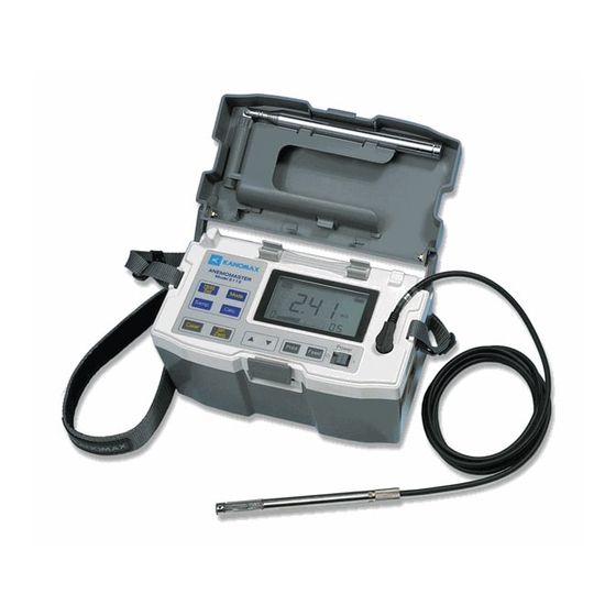
ANEMOMASTER
MODEL 6113/6114/6115
Operation Manual
取扱説明書本文にでてくる警告事項は、ご使用いただく前に
注意深く読み、よく理解してください。
いつでもご使用いただけるように大切に保管してください。
Please read this operation manual carefully and understand the warnings
described in this manual before operating the instrument.
Keep this manual handy for ready reference.
05001
08.04
Advertisement
Table of Contents

Related Manuals for Kanomax ANEMOMASTER Series


Summary of Contents for Kanomax ANEMOMASTER Series
- Page 1 ANEMOMASTER MODEL 6113/6114/6115 Operation Manual 取扱説明書本文にでてくる警告事項は、ご使用いただく前に 注意深く読み、よく理解してください。 いつでもご使用いただけるように大切に保管してください。 Please read this operation manual carefully and understand the warnings described in this manual before operating the instrument. Keep this manual handy for ready reference. 05001 08.04...
- Page 2 List of Components MODEL 6113/6114/6115 Item Model Features 6113 6114 6115 ● - - 6113-0J - ● - Main Body 6114 - - ● 6115 Air Velocity/Temperature ● ● ● Probe 6113-01 Probe ● ● ● Extension Rod 6112-03 960mm Probe Extension ●...
- Page 3 Safety Precautions Safety Precautions PLEASE READ CAREFULLY BEFORE PROCEEDING These precautions explain how to use the device correctly and safely, thereby preventing injury to yourself or to others. This section has been sub-divided into a WARNING section and a CAUTION section, according to the likelihood and nature of any potential injuries or damage inflicted.
- Page 4 Otherwise, there is an increased risk of electrical shock, fire or damage to the device. Return the device immediately to the nearest KANOMAX authorized service center.
- Page 5 Otherwise, there is an increased risk of damage to the device or personal injury. Have the device serviced regularly to ensure proper operation and accuracy. For information regarding service, contact your nearest KANOMAX Office or KANOMAX authorized service center. It is recommended the device be calibrated once a year.
-
Page 6: Table Of Contents
Table of Contents 1. Part Names and Functions ..................1 1.1 Main Body ......................... 1 1.2 Operation Panel......................3 1.3 Probe .......................... 4 1.4 Extension Rod ......................5 2. Getting Started ......................6 2.1 Installing Batteries ..................... 6 2.2 Confirming Probe Number ..................7 2.3 Connecting Probe ....................... - Page 7 6.4.1 Printing with Single Parameter Output Setting ............. 26 6.4.2 Digital Output with Single Parameter Output Setting ........... 26 6.5 Analog Output (Optional) ..................27 7. Function Settings ..................... 28 7.1 Changing Date and Time ..................28 7.2 Other Function Settings ................... 29 7.2.1 Setting Procedure ....................
-
Page 8: Part Names And Functions
1. Part Names and Functions 1. Part Names and Functions 1.1 Main Body Unit: mm Extension Rod Cable Lid (Probe storage area) Probe <Rotate> Approx. 210 Probe Connection Terminal Pressure Sensor Port Probe Rest Power Switch (Optional) LCD Display Operation Panel (To be used only when measuring*) I : ON O: OFF... - Page 9 1. Part names and Functions <Bottom View> ROM Cassette Probe Number Display Window Battery Compartment ROM Cassette Storage Area <Left Side View> Built-in Printer Printer Paper Cutter...
-
Page 10: Operation Panel
1. Part Names and Functions 1.2 Operation Panel When a key is pressed, you will hear a confirmation beep. You can turn the beep off in the function setting. Hold/Set Key: Press this key to hold/release the displayed value of the measurement mode. Also use this key to save the selected item in time/date setting mode and function setting mode. -
Page 11: Probe
1. Part Names and Functions 1.3 Probe Unit: mm Approx. φ10 Wind Direction Mark Air Velocity Sensor Temp. Compensation Sensor Temperature Sensor Approx. 23 Probe Number Approx. φ5 Cable Length: Approx. 2000 本体側... -
Page 12: Extension Rod
1. Part Names and Functions 1.4 Extension Rod Unit: mm Approx. 68 Connecting Probe Probe Extension Rod Approx. φ15... -
Page 13: Getting Started
2. Getting Started 2. Getting Started 2.1 Installing Batteries <Bottom View of the Instrument> 1) Press lightly with your fingers at points indicated and pull to open the battery cover. 2) Insert batteries in the order shown in the picture (1-6) making sure the polarity of the batteries. -
Page 14: Confirming Probe Number
2. Getting Started 2.2 Confirming Probe Number Confirm that the number on the probe and the number on the instrument (indicated on the ROM cassette in the bottom of the instrument) are same. * You need to confirm the probe number if you purchase multiple units or if you own a spare probe. (The probe number on the instrument is also displayed on the LCD when you Confirm that the... -
Page 15: Turning On/Off The Power
2. Getting Started 2.4 Turning ON/OFF the Power After you connect the probe to the instrument and turn the power ON, the software version followed by the probe number will be displayed. Then the Normal Measurement screen will show up. ON (Turn the power ON) O... -
Page 16: Precautions For Measurement
2. Getting Started 2.5 Precautions for Measurement 2.5.1 Air Velocity Measurement Precautions Wind Direction Mark Probe has its own directivity characteristics. Make sure that the wind direction mark is facing against the airflow. (For details on the directivity characteristics, refer to “12 Probe Directivity” in page 36.) If you are not sure Wind of the wind direction, slowly rotate the probe and make a measurement at the point where you get the maximum air velocity reading. - Page 17 2. Getting Started <Zero Adjustment Procedure> DISPLAY PROCEDURE Press key in the Measurement Mode to select pressure measurement. Each time you press the key, the measurement item changes in the order of Air Velocity -> Air Temperature -> Pressure. If you hold down key for over 2 seconds, you will hear a long beep sound, and the pressure will be indicated as “0.00”.
-
Page 18: Normal Measurement ***Measurement Mode
3. Normal Measurement 3. Normal Measurement *** Measurement Mode *** When the instrument is turned ON, the air velocity measurement screen will display automatically. The displayed measurement data is updated every 1 second. <Air Velocity Measurement Display> 3.1 Changing Measurement Mode DISPLAY PROCEDURE When the Normal Measurement screen in the left shows up, press... -
Page 19: Holding The Reading
3. Normal Measurement 3.2 Holding the Reading DISPLAY PROCEDURE While the Normal Measurement screen (Measurement Mode) is on the screen, press key. (You can also use this function in the Air Temperature Measurement Mode and Pressure Measurement Mode.) mark will appear at the upper right of the display while the reading is held. -
Page 20: Changing Time Constant
3. Normal Measurement 3.4 Changing Time Constant You can change the Time Constant only when measuring air velocity. The Time Constant for air temperature and pressure (optional for 6113/6114) is fixed at 1 second. DISPLAY PROCEDURE As you press key when the Normal Measurement screen (Air Velocity Measurement Mode) is displayed, the configured time constant shows up for a moment as shown in the left and then the time constant for measurement value will be changed. -
Page 21: Saving And Deleting Measurement Data
4. Saving and Deleting Measurement Data 4. Saving and Deleting Measurement Data 4.1 Saving Measurement Data (1) Saving Instantaneous Value DISPLAY PROCEDURE Press key when the Normal Measurement screen (Measurement Mode) is displayed. (This procedure can be performed in any measurement mode of measuring Air Velocity, Air Temperature, ℃... -
Page 22: Deleting Measurement Data
4. Saving and Deleting Measurement Data 4.2 Deleting Measurement Data 4.2.1 Deleting All: Deleting All Stored Measurement Data DISPLAY PROCEDURE Press keys simultaneously for 4 seconds or longer on the Normal Measurement screen (Measurement Mode). Then “n-00” will be displayed as shown in the left, and all of the stored data will be deleted. -
Page 23: Deleting Selected Data: Deleting Single Specified Stored Data
4. Saving and Deleting Measurement Data 4.2.3 Deleting Selected Data: Deleting Single Specified Stored Data DISPLAY PROCEDURE Press key 4 times on the Normal Measurement screen (Measurement Mode) to display the Stored Measurement Data Display in the Calculation Mode. (For details on Calculation Mode, refer to “5. Measuring AVG, MAX and MIN Value”... -
Page 24: Measuring Avg, Max And Min Value ***Calculation Mode
5. Measuring AVG, Max and Min Value 5. Measuring AVG, Max and Min Value *** Calculation Mode *** Calculation Mode calculates the maximum, minimum, and average value of the stored data. If there are no stored data, you must store measurement data first referring to “4. Saving and Deleting Measurement Data”... - Page 25 5. Measuring AVG, MAX and MIN Value DISPLAY PROCEDURE <Stored Measurement Data Display> The latest stored measurement data is displayed with the data number and bar graph. (The bar graph shows the rough indication of the stored data location.) In this display every time you press key, each of the stored measurement data is displayed as follows: Air Temperature →...
-
Page 26: Data Output
6. Data Output 6. Data Output 6.1 Printing Out Measurement Data (Only applicable to 6113) 6.1.1 Setting Printer Paper (Roll Paper) (1) Press lightly where indicated and pull the printer cover to open it. (2) Turn the power ON and press key. - Page 27 6. Data Output Head Lever (4) As you insert the leading edge of the roll paper, the roller will automatically rotate to reel in the paper and the paper comes out from the top. * If the paper is not set properly (the paper is placed diagonally or bent), pull the head lever up, remove the paper and repeat the above procedure from (2) to (4).
-
Page 28: Printing Out Instantaneous Value
6. Data Output 6.1.2 Printing Out Instantaneous Value DISPLAY PROCEDURE Press key on the Normal Measurement display (Measurement Mode) to hold the measurement values of the all parameters and print ℃ them out. (Air Velocity, Air Temperature and Pressure). Example of Print Out <Measurement Result>... -
Page 29: Printing Out Stored Data
6. Data Output 6.1.4 Printing Out Stored Data DISPLAY PROCEDURE Display the Calculation Mode (by pressing key in the Normal Measurement screen). While holding down key, press key to print out the calculation values (Average, Maximum and Minimum) of all the measurement parameters as well as the stored measurement data. -
Page 30: Printing Precautions
6. Data Output 6.1.6 Printing Precautions When printing out on the Model 6113’s built-in printer, the instrument draws a large current. If the battery is running low, enough current may not be provided to the printer as the battery’s voltage decreases dramatically. Consequently, temporary battery voltage drop occurs and the instrument’s voltage becomes lower than the level that it requires for operation, which may cause the instrument to stop working. -
Page 31: Digital Output
6. Data Output 6.2 Digital Output RS232C Terminal 6.2.1 Preparation for Digital Output To download the data stored in the ANEMOMASTER to your PC, connect the ANEMOMASTER to your PC using the RS232C cable (Optional). <What you need> ●Personal Computer ●RS-232C Cable (Sold Separately) ●Communication Software (Example: Windows has hyper terminal software.) <Baud Rate Setting>... -
Page 32: Entering Command From Pc To Output Data
6. Data Output 6.3 Entering Command from PC to Output Data To connect the ANEMOMASTER to your PC, refer to “6.2.1 Preparation for Digital Output” in page 24. Command Function ---Icon and its Meaning--- D**** To set how many data to read : Space Receive Interrupt : Line Break or Press Enter... -
Page 33: Transmission Of Stored Data (Data Stored In Memory)
6. Data Output 6.3.2 Transmission of Stored Data (Data stored in memory) DISPLAY PROCEDURE <To output stored data volume> Enter “P ”. After the command is received, “AP” will be returned and the P0012 amount of stored data will be output. DISPLAY PROCEDURE <To output stored data>... -
Page 34: Analog Output (Optional)
6. Data Output 6.5 Analog Output (Optional) Analog Output Terminal (1) Data Update Interval : 0.1 seconds (2) Load Impedance: 5KΩ or higher (3) Output Current : DC 0~1V For analog output, select one setting from the output range listed in the table below. -
Page 35: Function Settings
7. Function Settings 7. Function Settings 7.1 Changing Date and Time DISPLAY PROCEDURE Press keys simultaneously for 2 seconds or longer on the Normal Measurement screen (Measurement Mode). The set-up phase number that indicates what you are adjusting appears at the bottom left, and the last 2 digits of the year flash. Use keys to adjust the year. -
Page 36: Other Function Settings
7. Other Settings 7.2 Other Function Settings You can configure the baud rate, measurement units, data output parameters using the bit settings on the screen (Soft Dip Switch). Once the setting is stored, it will not be lost even if the instrument is turned OFF because of the back-up batteries. -
Page 37: Dip Switch Setup Chart
7. Other Settings 7.2.2 Dip Switch Setup Chart = Factory Default Setting Setup Parameter Specification Bit Status Display 4800bps b0:00 b1:00 9600bps b0:01 b1:00 Baud Rate Setting [b0, b1] 19200bps b0:00 b1:01 38400bps b0:01 b1:01 - b2:00 Buzzer ON/OFF Setting [b2] -... -
Page 38: Cleaning Probe
8. Cleaning Probe 8. Cleaning Probe If the sensor is contaminated with impurities such as dust, particles, soot or machine oil, the heat dissipation rate will change causing inaccurate readings. In most cases, as heat dissipation decreases, the air velocity readings will also decrease. -
Page 39: Specifications
9. Specifications 9. Specifications Product Anemomaster Model 6113/6114/6115 Measuring Object Clean air flow Measuring Range 0.10 ~ 50.0m/s Resolution 0.00 ~ 9.99m/s:0.01m/s, 10.0~50.0m/s:0.1m/s Accuracy ±(3% of the reading + 0.1) m/s Velocity Approx. 1sec (at Air Velocity: 1m/s, Response: 90%) Response Time Temp.Compensation ±(5% of the reading + 0.1)m/s in the temperature range of 5 ~ 80℃... -
Page 40: Measurement Principles
10. Measurement Principles 10. Measurement Principles 10.1 Hot-wire Anemomaster Principle When the heated air velocity sensor is exposed to airflow, Current the sensor temperature will change by the heat drawn by the airflow. Accordingly, the sensor resistance values will change. This change in the resistance values will Airflow Cooling vary largely as the air velocity increases. -
Page 41: Air Volume Calculation
10. Measurement Principles Constant Voltage Air Temperature Measurement An air temperature element (platinum thin film element) whose resistance value changes by the air temperature is incorporated in one side of the bridge. The air temperature can be obtained by measuring the variance in Output the resistance value. -
Page 42: Air Velocity Compensation
11. Air Velocity Compensation 11. Air Velocity Compensation The air velocity sensor of this instrument is heated. The air flowing past the heated sensor removes heat from the sensor. The instrument uses the relation between how much heat removed (dissipation heat) and air velocity to indicate the air velocity. -
Page 43: Probe Directivity (Air Velocity)
12. Probe Directivity 12. Probe Directivity (Air Velocity) 12.1 Horizontal Directivity Wind Direction Mark 90° -180° 0° -90° When Air Velocity is 5m/s 12.2 Vertical Directivity Wind Direction Mark 0° -90° 90° -180° When Air Velocity is 5m/s... -
Page 44: Troubleshooting
Probe/Probe Cable may not be connected property. → Check probe connection. Probe/Probe Cable wire is disconnected or the sensor is damaged. → Contact your local KANOMAX Office or service center. Incorrect air velocity reading Confirm that the direction mark of the probe is facing against the airflow. -
Page 45: Printing
13. Troubleshooting 13.4 Printing Refer To Symptom Possible Cause(s) / Solution(s) (Page No.) Printing Failure Printing paper may not be installed properly. → Open the printer cover and confirm there is no ejected paper caught inside the printer. Printing paper may be running short. →... -
Page 46: Warranty And After-Sales Service
14. Warranty and After-sales Service KANOMAX Limited Warranty The limited warranty set below is given by KANOMAX with respect to the KANOMAX brand anemometer, its attachment parts including Probe and other accessories (hereafter referred to as “PRODUCT”) that you have purchased. - Page 47 Repair parts are retained for a minimum period of five (5) years after production cessation of the PRODUCT. This storage period of repair parts is considered as the period during which KANOMAX can provide repair service.
- Page 48 U.S.A. & Europe KANOMAX USA, INC. PO Box 372, 219 Route 206, Andover, NJ 07821 U.S.A. TEL: (800)-247-8887 / (973)-786-6386 FAX: (973)-786-7586 URL: http://www.kanomax-usa.com/ E-Mail: info@kanomax-usa.com Japan & Asia KANOMAX JAPAN, INC. 2-1 Shimizu Suita City, Osaka 565-0805, Japan TEL: 81-6-6877-0183 FAX: 81-6-6877-5570 URL: http://www.kanomax.co.jp/...