Table of Contents
Advertisement
Quick Links
Advertisement
Table of Contents

Related Manuals for Kanomax TABmaster Mini


Summary of Contents for Kanomax TABmaster Mini
- Page 1 TABmaster Mini Model 6750 User's Manual...
-
Page 2: Overview
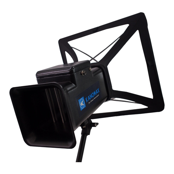
Overview TABmaster Mini (Model 6750) is a portable airflow meter for measuring airflow at the intake and exhaust points of a HVAC system. The size of the provided hood is 355×355 mm (approximately 14” x 14”). The edge of the hood, that touches walls or other surfaces, is hemmed with a dust- and stain- repellent urethane material. -
Page 3: Important Safety Information
Important Safety Information The symbols for the warnings in this manual are defined as below: Classifications Danger: To Prevent Serious Injury or Death Warnings in this classification indicate a danger that may result in serious injury or death if not observed. Caution: To Prevent Damage to the Product Warnings in this classification indicate risk of damage to the Product that may void the product warranty if not observed. - Page 4 Caution Always unplug the instrument from the electrical outlet when it is not in use. Handle Failure to do this may cause an electric shock, fire or circuit damage. properly Do not expose the instrument to rain or water drops. Otherwise, it may cause an electric shock, fire or circuit damage.
- Page 5 Do not move this instrument from a cold place to a warm place quickly. It will cause condensation. Even when used in an environment within the specified operating Forbidden temperature and humidity, a sudden temperature change may cause condensation. Condensation generated on the sensor may cause inaccurate measurements.
-
Page 6: Table Of Contents
Table of Contents Overview ....................... 2 List of Components ....................2 Important Safety Information ................3 Chapter 1 Part Names and Functions ..............7 Main Body ......................7 Indicator ......................8 Hood ........................ 8 Extension Rod ....................8 Chapter 2 Installing and Assembling the Hood ............. 9 Installing the Hood .................. -
Page 7: Chapter 1 Part Names And Functions
Chapter 1 Part Names and Functions Hood Main body Main body-indicator cable Extension rod Indicator Main Body ■External structure Indicator connector Airflow detecting port Extension rod fixing screw ■Internal structure Rectifying honeycomb Support pole Pole mounting hole ■Sampling Tube Matrix Measures airflow at 16 measuring points. -
Page 8: Indicator
Indicator ■Front [POWER] button Liquid crystal display Operation Power supply button terminal ■Back Battery Cover Cover Lock ■Top Main body [POWER] connector Button Hood Clear Support hood Pole Hood edge urethane rubber Frame Extension Rod Indicator Fixing jig Extension rod Grip... -
Page 9: Chapter 2 Installing And Assembling The Hood
Chapter 2 Installing and Assembling the Hood Installing the Hood Match the stitching lines of the fabric hood to the corners of the main body to install the hood. If the hood is twisted, it cannot be installed properly. Assembling the Hood and Frame ●Insert the tip of the support pole into the pole mounting hole (see Fig. -
Page 10: Assembling The Indicator And Jig
●Connect the tip of the extension rod to the extension rod connecting base. Adjust the angle as required and lock it. Extension rod connecting base Turn lock When storing the instrument in the carrying case, remove the hood and extension rod so as not to damage the carrying case. Assembling the Indicator and Jig ●Open the turn knob of the indicator fixing jig and attach the jig to the extension rod. -
Page 11: Chapter 3 Operation Procedure
Chapter 3 Operation Procedure AC-powered Operation With batteries installed, Connect the AC Adaptor (optional item) to the instrument to supply power from the AC adaptor. Specification of the AC Adaptor Input: AC 110 to 240V, 50/60 HZ Output: DC 5V/ 2A AC-powered operation is available. -
Page 12: Turning The Power On/Off
A new measurement cannot be started. The current measurement might be interrupted. Setting operations for various functions might be interrupted Do not use a new (fully charged) batteries and low-charged batteries at the same time. Turning the Power ON/OFF Turning the Power On Hold down the [POWER] button at the top of the indicator. -
Page 13: Operating The Instrument
Operating the Instrument Use the operation button on the indicator to operate the instrument. Grayed-out functions shown on the LCD screen are inactive ones. mark on the LCD screen means pressing the operation button once; the mark means holding down the operation button for more than 2 seconds. -
Page 14: Chapter 4 Taking A Measurement
Chapter 4 Measurement Main Screen After turning the power ON, the screen will automatically move to atmospheric pressure manual setting screen and the current set value of atmospheric pressure will be displayed. Pressing ▲ ▼ will set the atmospheric pressure value. Pressing will store the setting and move to the main screen for measurement. - Page 15 says - - - . After a certain period of time, the measured value will be displayed.(The measured value is updated once a second.) Note: The displayed airflow value is an instantaneous value of every second. To interrupt the ongoing measurement, press the [停止] button ( ).
-
Page 16: Chapter 5 Menu Operation
Chapter 5 Menu Operation Displaying the Menu Screen Hold down on the measurement main screen for more than 2 seconds to display the menu screen. On the menu screen, the following Five (6) items can be set: ID Set (ID Setting) Display (Read data) Delete (Delete data) UPlink (Send data) -
Page 17: Display(Read
Select [2. New ID] Select [2. 新規 ID (New ID)] to set a new ID. Hold down Press to add a new ID, and tap to cancel to add a new ID. No data is stored in a new ID If no measurement data is stored in a new ID, an additional new ID cannot be created. -
Page 18: Delete(Delete
Press Press to go back to the previous screen. Delete (Delete data) Select [Delete] on the menu screen. [Delete All], [Delect by ID] and [Delete by No.] are available. to go back to the [Delete] screen. to go back to the menu screen. Delete(Delete All)... -
Page 19: Uplink(Send
Delete by Data No. Entry This function deletes a selected data. Press to select [3.Data to Delete (Delete data]. Make selection by pressing Press to select the ID number to be deleted. Press to select the Data number to be deleted. Hold down for 2 seconds to display the confirmation message. -
Page 20: Print Settings
The indicator is connected to the PC. With the menu screen displayed, press to select [ 転 送 (Send)]. Press to move to the 転送 (Send) screen. Press to start the connection. Press to cancel the connection. Press start connection between the main body and the PC. - Page 21 With the menu screen displayed, press to select [印字 (Printing)]. Press to move to the Print Setting (印字設定) screen. Press to go back to the previous screen. Print by ID Entry Press to select [1. Print by ID (Print by ID Entry)]. Press to go back to the setting screen.
- Page 22 Bluetooth With the menu screen displayed, press to select [Set] Press to move to the setting screen. Hold down for 2 seconds to display the [Model name-serial number] Hold down for 2 seconds to cancel. To connect from OS device (iPhone, iPad) to 6750, can operate 6750 from OS device and it can send the data with e-mail.
-
Page 23: Chapter 6 Other Settings
Chapter 6 Other Settings Setting Screen Hold down the ▲ buttons at the same time and turn the power ON to move to the setting screen as below. Press ▲or to select the setting items and press to set ▼ measurement unit and K factor for each item. -
Page 24: Setting And Storing The Temperature Unit
Setting and Storing the Temperature Unit Select [2.Temp(Temperature)] and press button to display the list of [℃] and [°F]. The currently selected unit is highlighted in white as shown in the lower right figure. Press ▲ ▼ to select the unit and press to store the setting of the unit. - Page 25 The range of settable K factor is from 0.500 to 1.500, at 0.001 intervals. Note: If ▲ is pressed when displaying 1.500, the setting will be changed to 0.500; if ▼ is pressed wen displaying 0.500, the setting will be changed to 1.500.
-
Page 26: Chapter 7 Main Specifications
Chapter 7 Main Specification MODEL 6750 Airflow ±8 to 600 m³/h Measuring Range Temperature 0 to 50℃ 8~350 m /h︓±(Reading x 3%+1digit m /h) Airflow Measuring 350 to 600 m /h︓±(Reading x 5%+1digit m /h) Accuracy ±0.5℃ Temperature Airflow Resolution Temperature 0.1℃... -
Page 27: Chapter 8 Troubleshooting
Chapter 8 Troubleshooting Problem Possible Cause(s)/ Solution(s) Batteries are inserted in wrong polarity. → Turn the power OFF and insert the battery correctly. No display on the The battery level is low. screen →Turn off the instrument and replace the batteries with new ones. -
Page 28: Chapter 9 Warranty And After-Sales Services
Chapter 9 Warranty and After-sales Services The limited warranty set forth below is given by KANOMAX JAPAN, Inc. (hereafter referred to as “KJI”) with respect to the KANOMAX brand airflow meter, and its attachment parts including other accessories (hereafter referred to as “PRODUCT”) purchased directly from KJI or from and authorized distributor. -
Page 29: Contact Information
Contact Information U.S.A. KANOMAX USA, INC. PO Box 372, 219 Route 206, Andover, NJ 07821 U.S.A. TEL: (800)-247-8887 / (973)-786-6386 FAX: (973)-786-7586 URL: http://www.kanomax-usa.com/ E-Mail: info@kanomax-usa.com JAPAN KANOMAX JAPAN, INC. 2-1 Shimizu, Suita City, Osaka 565-0805, Japan TEL: 81-6-6877-0183 FAX: 81-6-6879-5570 URL: http://www.kanomax.co.jp...