Table of Contents
Advertisement
Quick Links
SB-HFS4810
Notes: Please refer to the original service manual for:
• Speaker system
SB-HFS4810/HC4010
SB-HW6010
DVD Home Theater Sound System
Remote
SB-HC4010
Control
SB-HW6010
SA-XH385
Order No:AD1403015CE
Order No:AD1404027CE
SC-XH385GA
Model No.
SC-XH385GS
SA-XH385GA
SA-XH385GS
Color: (K)...........Black Type
© Panasonic Corporation 2014
Unauthorized copying and distribution is a violation of law.
ORDER NO.AD1404025CE
Advertisement
Table of Contents

Related Manuals for Panasonic SC-XH385GA


Summary of Contents for Panasonic SC-XH385GA
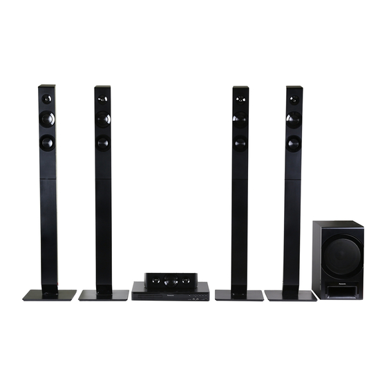
- Page 1 Remote SB-HC4010 Control SB-HW6010 SB-HFS4810 SA-XH385 Color: (K)...Black Type Notes: Please refer to the original service manual for: • Speaker system Order No:AD1403015CE SB-HFS4810/HC4010 Order No:AD1404027CE SB-HW6010 © Panasonic Corporation 2014 Unauthorized copying and distribution is a violation of law.
-
Page 2: Table Of Contents
TABLE OF CONTENTS PAGE 1 Safety Precautions ------------------------------------------------3 1.1. General Guidelines ------------------------------------------3 1.2. Leakage Current Cold Check ------------------------------3 1.3. Leakage Current Hot Check (See Figure 1.) ----------3 1.4. Protection Circuitry -------------------------------------------3 2 Warning ---------------------------------------------------------------4 2.1. Prevention of Electrostatic Discharge (ESD) to Electrostatically Sensitive (ES) Devices ------------4 2.2. -
Page 3: Safety Precautions
1 Safety Precautions 1.1. General Guidelines 1. IMPORTANT SAFETY NOTICE There are special components used in this equipment which are important for safety. These parts are marked by in the Exploded Views and Replacement Parts List. It is essential that these critical parts should be replaced with manufacturer’s specified parts to prevent X-RADIATION, shock, fire, or other hazards. -
Page 4: Warning
2 Warning 2.1. Prevention of Electrostatic Discharge (ESD) to Electrostatically Sensitive (ES) Devices Some semiconductor (solid state) devices can be damaged easily by static electricity. Such components commonly are called Electrostatically Sensitive (ES) Devices. Examples of typical ES devices are IC(integrated circuits)and some field-effect transistors and semiconductor “chip”... -
Page 5: Caution For Ac Cord (For The Saudi Arabia, Kuwait And Africa)
A replacement fuse cover can be purchased from your local Panasonic Dealer. If the fitted moulded plug is unsuitable for the socket outlet in your home then the fuse should be removed and the plug cut off and disposed of safety. -
Page 6: Precaution Of Laser Diode
2.3. Precaution of Laser Diode CAUTION : This product utilizes a laser diode with the unit turned “on”, invisible laser radiation is emitted from the pick-up lens. Wave length:770 to 800 nm (CDs)/645 to 660 nm (DVDs) Maximum output radiation power from pick-up:100 μW/VDE Laser radiation from the pick-up lens is safety level, but be sure the followings: 1. -
Page 7: Static Electricity Protection Measures
2.4. Static Electricity Protection Measures • The laser diode in the traverse unit (optical pick-up) may break down due to potential difference caused by static electricity of clothes or human body. So, be careful of electrostatic breakdown during repair of the traverse unit (optical pick-up). 2.5. -
Page 8: Service Navigation
3 Service Navigation 3.1. Service Information This service manual contains technical information, which allow service personnels to understand and service this model. Please place orders with the part numbers in the parts list, not the numbers in the exploded views. If the circuit is changed or modified, the information will be followed by service manual to be controlled with original service manual. - Page 9 Set the CD-R disc or USB memory device into the DVD Theater and playback it. When the message of recommending the “Software Update” appears on the display monitor, select the Left cursor button: [Yes] or the Right cursor buttons :[No] and press the [OK] button with the remote control.
-
Page 10: Specifications
4 Specifications GENERAL SPEAKER SECTION Super Woofer Full range Power consumption Approx. 76 W tweeter CONE TYPE CONE TYPE Power consumption in Approx. 0.5 W (cm) (cm) Piezo type standby mode Front Power supply AC 220 V to 240 V, 50 Hz/60 Hz Centre Dimensions (W H D) 430 mm... -
Page 11: Others (Licences)
“DVD Logo” is a trademark of DVD Format/Logo Licensing Corporation. The Bluetooth ® word mark and logos are owned by the Bluetooth SIG, Inc. and any use of such marks by Panasonic Corporation is under license. Other trademarks and trade names are those of their respective owners. -
Page 12: Location Of Controls And Components
5 Location of Controls and Components 19 21... - Page 13 Turn the unit on and off Move the highlight for selection [OK] Turn the TV on and off Confirm the selection [AV, INPUT] [OPTION] Switch the input select of TV Show Option menu ( [RETURN ]/[ PAIRING] (Bluetooth) Return to previous screen Select Bluetooth ®...
-
Page 14: Installation Instructions
AUDIO OUT VIDEO IN Non-HDMI-compliant cables cannot be utilized. It is recommended that you use Panasonic’s HDMI cable. When outputting 1080p signal, please use Vi d e o C a b l e HDMI Cable HDMI cables 5.0 meters or less. -
Page 15: Operating Instruction
7 Operating Instruction 7.1. Take out the Disc from the Drive Unit when the Disc cannot be ejected by the OPEN/CLOSE button 7.1.1. When the Disc Eject can not be done. 1. Turn off the power and pull out the AC cord. 2. -
Page 16: Troubleshooting Guide
( above) For some built-in Bluetooth devices, you ® have to set the audio output to “Panasonic This unit does not recognize the USB connection correctly. XH” manually. Read the operating instructions for the device for details. -
Page 17: About Circuit
8.2. About Circuit Before the syptom check remove the power cable and reinsert it after 10 sec. If the unit is still NG, please refer to below syptoms. Symptom - 1 No Power Check the AC cord. Exchange the AC cord. (cutting or damage…etc) Check the Power supply Exchange the Fuse. - Page 18 Symptom - 2 No LED display /Keys do not work Check the Digital P.C.B. Exchange the Digital P.C.B. connector (XS4)*3 voltage. Check the FFC cable *4 Exchange the FFC cable. connecting Digital P.C.B. and Front panel P.C.B. Exchange the Front panel P.C.B. VOLTAGE DATA (measurement value) CHECK POINT LOCATION 3.3V...
- Page 19 Symptom - 3 Can not OPEN or CLOSE Check the OPEN/ CLOSE Exchange the mechanism SW.(Break or click feeling…etc) Check the connector (XP135*5/ Check the symptom -1 XP136*6) voltage on the Digital P.C.B. Exchange the Mechanism unit. VOLTAGE DATA (measurement value) CHECK POINT LOCATION 1.3V 3.4V...
- Page 20 Symptom - 4 No picture, No sound Check the k th Check symptom -3, Disc tray Operation. afterwards check (OPEN and COLSE) symptom -4. Check the Operation Check the connector and FL display. and FL display. (XP135*5) voltage on (XP135 5) voltage on 1.
-
Page 21: Wiring Connection And Voltage Data
9 Wiring Connection and Voltage Data Digital P.C.B. Power Mechanism Supply Unit P.C.B. Front Panel P.C.B. MIC P.C.B. - Page 22 VOLTAGE DATA (measurement value) PIN NO. VALUE PIN NO. VALUE PIN NO. VALUE 1.3V 3.3V 3.1V 3.4V 3.3V 3.3V 3.3V 2.5V 11.1V 2.4V PIN NO. VALUE 3.3V 3.3V 3.3V 1.2V 2.6V 0.5V 3.3V PIN NO. VALUE PIN NO. VALUE PIN NO. VALUE 3.2V 11.2V PIN NO.
-
Page 23: Disassembly And Assembly Instructions
10 Disassembly and Assembly Instructions 10.1. Disassembly Flow Chart The following chart is the procedure of disassembling the casing and inside parts for internal inspection when carrying out the servicing. To assemble the unit, reverse the steps shown in the chart below. 1. - Page 24 10.3. Disassembly Procedure 10.3.2.2. Front Panel Unit 1. Disconnect the connector (A), connector (B),and FFC 10.3.1. Top Panel cable. 2. Unlock 5 tabs (A) - (E). 1. Remove the 6 Black Screws. 3. Pull the Front Panel Unit in the direction (1). 2.
- Page 25 4. Remove 1 Screw (C) to remove the MIC P.C.B unit.. 10.3.5. Fan Motor Unit 1. Remove the 2 Screws (A). 2. Remove the connector (A), then remove the Fan Motor Unit in directon of (1). Screws (A) Connector (A) Fan Motor Unit Screw (C) MIC P.C.B.
- Page 26 10.3.7. Mechanism Unit 10.3.8. AC Inlet Unit 1. Remove 2 Screws (C) and the Wire Tie. 1. Detach the lead wires fixed at the hooking part. 2. Lift upward the Digital P.C.B. to remove it. 2. Unlock the 2 tabs (A) and remove the AC Inlet Unit. (When assembling, first set the Mechanism unit to tabs (A) then tighten the 2 Screws (C).) AC Inlet Unit...
-
Page 27: Replacement Parts List And Exploded View
11 Replacement Parts List and Exploded View 11.1. Replacement Parts List Notes: *Important safety notice: Components identified by mark have special characteristics important for safety. When replacing any of components, be sure to use only manufacture’s specified parts shown in the parts list. *Parts marked with [PJM] in the remarks column are supplied by PAVCJM, others are supplied by PHK. -
Page 28: Casing Parts & Mechanism Section
11.2. Casing Parts & Mechanism Section 164 165 141 142... -
Page 29: Packing & Accessories Section
11.3. Packing & Accessories Section ACCESSORIES BAG A3 FM INDOOR ANTENNA SB-HW6010 OI BOOK SA-XH385 QSG OI PREPARATIOPN VER.) SPEAKER CABLE STICKER BATTERIES (NOT SUPPLIED) SB-HC4010 SCREWS (NOT SUPPLIED) AC CORD FOR GA ONLY SB-HFS4810 AC CORD FOR GS ONLY AC CORD FOR GA &...