Table of Contents
Advertisement
Quick Links
SERVICE MANUAL
MMK-AP0073HP1-E1 (TR1)
MMK-AP0093HP1-E1 (TR1)
MMK-AP0123HP1-E1 (TR1)
MMK-AP0153HP1-E1 (TR1)
MMK-AP0183HP1-E1 (TR1)
MMK-AP0243HP1-E1 (TR1)
• This Service Manual describes contents of the new High Wall indoor unit.
For the outdoor unit, refer to the Manual with FILE NO. A03-009, A05-004, A05-015.
• The service parts will be supplied by TCTC.
FILE NO. SVM-16046-2
<High Wall Type>
Revised on November, 2018
Advertisement
Table of Contents

Related Manuals for Toshiba MMK-AP0073HP1-E1


Summary of Contents for Toshiba MMK-AP0073HP1-E1
- Page 1 FILE NO. SVM-16046-2 SERVICE MANUAL <High Wall Type> MMK-AP0073HP1-E1 (TR1) MMK-AP0093HP1-E1 (TR1) MMK-AP0123HP1-E1 (TR1) MMK-AP0153HP1-E1 (TR1) MMK-AP0183HP1-E1 (TR1) MMK-AP0243HP1-E1 (TR1) • This Service Manual describes contents of the new High Wall indoor unit. For the outdoor unit, refer to the Manual with FILE NO. A03-009, A05-004, A05-015.
-
Page 2: Table Of Contents
FILE NO. SVM-16046 CONTENTS SAFETY CAUTION .................... 3 1. CONSTRUCTION VIEWS (EXTERNAL VIEWS)......... 8 2. WIRING DIAGRAM ..................9 3. PARTS RATING ..................10 4. REFRIGERATING CYCLE DIAGRAM ............60 5. CONTROL OUTLINE ................61 6. APPLIED CONTROL ................68 7. -
Page 3: Safety Caution
FILE NO. SVM-16046 SAFETY CAUTION The important contents concerned to the safety are described on the product itself and on this Service Manual. Please read this Service Manual after understanding the described items thoroughly in the following contents, and keep them. WARNING Before troubleshooting or repair work, check the earth wire is connected to the earth terminals of the main unit, otherwise an electric shock is caused when a leak occurs. - Page 4 FILE NO. SVM-16046 WARNING After repair work, surely assemble the disassembled parts, and connect and lead the removed cables as before. Perform the work so that the cabinet or panel does not catch the inner cables. If incorrect assembly or incorrect cable connection was done, a disaster such as a leak or Assembly/Cabling fire is caused at user’s side.
- Page 5 FILE NO. SVM-16046 • New Refrigerant (R410A) This air conditioner adopts a new HFC type refrigerant (R410A) which does not deplete the ozone layer. 1. Safety Caution Concerned to New Refrigerant The pressure of R410A is high 1.6 times of that of the former refrigerant (R22). Accompanied with change of refrigerant, the refrigerating oil has been also changed.
- Page 6 FILE NO. SVM-16046 4. Tools (1) Required Tools for R410A Mixing of different types of oil may cause a trouble such as generation of sludge, clogging of capillary, etc. Accordingly, the tools to be used are classified into the following three types. 1) Tools exclusive for R410A (Those which cannot be used for conventional refrigerant (R22)) 2) Tools exclusive for R410A, but can be also used for conventional refrigerant (R22) 3) Tools commonly used for R410A and for conventional refrigerant (R22)
- Page 7 FILE NO. SVM-16046 5. Recharge of Refrigerant When recharge of the refrigerant is required, charge the new refrigerant with the specified amount in the procedure as described below. Recover the refrigerant and check there is no refrigerant in the equipment. When the pressure has lowered until indication of the compound gauge pointed -0.1MPa (–76cmHg), open fully the handle Low and turn off the power of vacuum pump.
-
Page 8: Construction Views (External Views)
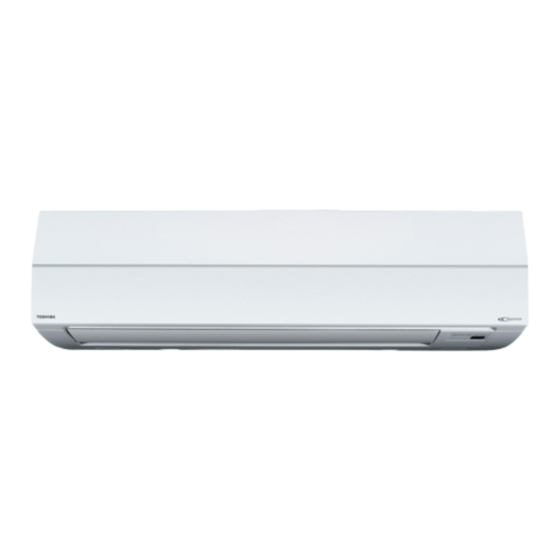
FILE NO. SVM-16046 1. CONSTRUCTION VIEWS (EXTERNAL VIEWS) 1-1. Indoor Unit Model: MMK-AP0073HP1-E1 (TR1), MMK-AP0093HP1-E1 (TR1), MMK-AP0123HP1-E1 (TR1), MMK-AP0153HP1-E1 (TR1), MMK-AP0183HP1-E1 (TR1), MMK-AP0243HP1-E1 (TR1) 1050 Front panel Air filter Air inlet Heat exchanger Knock out system Knock out system 72 78... -
Page 9: Wiring Diagram
FILE NO. SVM-16046 2. WIRING DIAGRAM Model: MMK-AP0073HP1-E1 (TR1), MMK-AP0093HP1-E1 (TR1), MMK-AP0123HP1-E1 (TR1), MMK-AP0153HP1-E1 (TR1), MMK-AP0183HP1-E1 (TR1), MMK-AP0243HP1-E1 (TR1) Louver motor motor 5 4 3 2 1 GRN & YEL Heat Outdoor unit 6 5 4 3 6 5 4 3 2... -
Page 10: Parts Rating
FILE NO. SVM-16046 3. PARTS RATING 3-1. Parts Rating Parts Name Type Specications ICF-340-30-4 Fan motor (for indoor) Output (Rated) 30W,340V DC Grille motor MP24Z3N Output (Rated) 1W, 16 poles DC 268mm Thermo. Sensor (TA sensor) 10kΩ at 25°C Heat exchanger sensor (TC1 sensor) Ø4,650mm 10kΩ... - Page 11 FILE NO. SVM-16046 3-3. Parts Name of Remote Controller n Display section In the display example, all indicators are displayed for the explanation. Display In reality only, the selected contents are indicated. section • When turning on the main power switch and leak breaker at the first TEMP.
- Page 12 FILE NO. SVM-16046 9 20 19 Air volume select display Unit Number display The selected air volume mode is displayed. Unit number of the indoor unit selected with the unit select button or abnormal indication (AUTO) (HIGH) of the indoor/outdoor unit. (MED.) (LOW) Central control display...
- Page 13 FILE NO. SVM-16046 n Operation section Push each button to select a desired operation. • The details of the operation needs to be set up once, afterward, the air conditioner can be used by ON / OFF pushing button only. TEMP.
- Page 14 FILE NO. SVM-16046 3-4. Correct Usage • When you use the air conditioner for the first time or when you change the SET DATA value, follow the procedure below. ON / OFF From the next time, the operation displayed on the remote controller will start by pushing the button only.
- Page 15 FILE NO. SVM-16046 [In case of cooling] • Start the cooling operation after approx. 1 minute. [In case of heating (For Heat-pump model only)] • The heating operation mode is selected in accordance with the room temperature and operation starts after approximately 3 to 5 minutes.
- Page 16 FILE NO. SVM-16046 u 4-way Air Discharge Cassette Type (1H series), Compact 4-way Type • When the air conditioner is not operating, the louvers automatically direct downward. • While the air conditioner is in ready status for heating, the louvers direct upward. The swinging operation starts after heating ready status has been cleared, but “SWING ”...
- Page 17 FILE NO. SVM-16046 TIMER SET MODE TIME SAVE VENT FILTER RESET TEST SWING/FIX UNIT LOUVER Unit select button n How to set up the wind direction n How to stop swinging SWING/FIX SWING/FIX Push during operation. Push at a desired position while the louver is swinging.
- Page 18 FILE NO. SVM-16046 3-6. Timer Operation • A type of timer operation can be selected from the following three types. (Setting of up to 168 hours is enabled.) OFF timer : The operation stops when the time of timer has reached the set time. Repeat OFF timer : Every time, the operation stops after the set time has passed.
- Page 19 FILE NO. SVM-16046 3-7. Installation Installation place CAUTION • Check that the air conditioner is not installed in a place subject to combustible gas leak. Accumulation of combustible gas around the unit may cause a fire. • Drain the dehumidified water from the indoor unit and outdoor unit to a well-drained place. •...
- Page 20 FILE NO. SVM-16046 3-8. Maintenance WARNING Be sure to turn off the main power switch prior to the maintenance. • Please do not intend to do the daily maintenance and/or Air Filter cleaning by yourself. Cleaning of the air filter and other parts of the air filter involves dangerous work in high places, so be sure to have a service person do it.
- Page 21 FILE NO. SVM-16046 NOTE • For environmental conservation, it is strongly recommended that the indoor and outdoor units of the air conditioner in use be cleaned and maintained regularly to ensure efficient operation of the air conditioner. When the air conditioner is operated for a long time, periodic maintenance (once a year) is recommended. Furthermore, regularly check the outdoor unit for rust and scratches, and remove them or apply rustproof treatment, if necessary.
- Page 22 FILE NO. SVM-16046 u High Wall Type • Open the air inlet grille. Lift the air inlet grille up to the horizontal position. • Take hold of the left and right handles of the air filter and lift it up slightly, then pull downward to take it out from the filter holder.
- Page 23 FILE NO. SVM-16046 3-9. Air Conditioner Operations and Performance Check before operation WARNING • Check whether earth wire is disconnected or out of place. • Check that air filter is installed to the indoor unit. Turn on the power switch 12 hours or more •...
- Page 24 FILE NO. SVM-16046 3-10. When the Following Symptoms are Found Check the points described below before asking repair servicing. Symptom Cause Outdoor unit • White misty cold air or • Fan of the outdoor unit stops automatically and performs defrost water is out.
- Page 25 FILE NO. SVM-16046 Confirmation and check When a trouble occurred in the air conditioner, the check code and the indoor unit No. appear on the display part of the remote controller. The check code is only displayed during the operation. If the display disappears, operate the air conditioner according to the following “Confirmation of error history”...
- Page 26 The qualified service person is a person who installs, repairs, maintains, relocates and removes the air conditioners made by Toshiba Carrier Corporation. He or she has been trained to install, repair, maintain, relocate and remove the air conditioners made by Toshiba Carrier Corporation...
- Page 27 Installation Manual SMMS High-Wall Type Definition of Protective Gear When the air conditioner is to be transported, installed, maintained, repaired or removed, wear protective gloves and ‘safety’ work clothing. In addition to such normal protective gear, wear the protective gear described below when undertaking the special work detailed in the table below.
- Page 28 Installation Manual SMMS High-Wall Type Warning indications on the air conditioner unit ■ Warning indication Description WARNING WARNING ELECTRICAL SHOCK HAZARD Disconnect all remote ELECTRICAL SHOCK HAZARD electric power supplies Disconnect all remote electric power supplies before servicing. before servicing. WARNING WARNING Moving parts.
- Page 29 Installation Manual SMMS High-Wall Type PRECAUTIONS FOR SAFETY • Ensure that all Local, National and International regulations are satisfied. • Read this “PRECAUTIONS FOR SAFETY” carefully before Installation. • The precautions described below include the important items regarding safety. Observe them without fail. • After the installation work, perform a trial operation (test run) to check for any problem. Follow the Owner’s Manual to explain how to use and maintain the unit to the customer. • Turn off the main power supply switch (or breaker) before the unit maintenance. • Ask the customer to keep the Installation Manual together with the Owner’s Manual. The manufacturer shall not assume any liability for the damage caused by not observing the description of this manual.
- Page 30 Installation Manual SMMS High-Wall Type Installation • Install the air conditioner securely in a location where the base can sustain the weight adequately. If the strength is not enough, the unit may fall down resulting in injury. • Follow the instructions in the Installation Manual to install the air conditioner. Failure to follow these instructions may cause the product to fall down or topple over or give rise to noise, vibration, water leakage or other trouble.
- Page 31 Installation Manual SMMS High-Wall Type Explanations given to user • Upon completion of the installation work, tell the user where the circuit breaker is located. If the user does not know where the circuit breaker is, he or she will not be able to turn it off in the event that trouble has occurred in the air conditioner. • If the fan grille is damaged, do not approach the outdoor unit but set the circuit breaker to the OFF position, and contact a qualified service person(*1) to have the repairs done. Do not set the circuit breaker to the ON position until the repairs are completed.
- Page 32 Installation Manual SMMS High-Wall Type ACCESSORY PARTS Part name Q’ty Shape Usage (Hand over to customers) (For other languages that do not appear in Installation Manual This manual this installation Manual, please refer to the enclosed CD-R.) (Hand over to customers) (For other languages that do not appear in Owner’s Manual this installation Manual, please refer to the...
- Page 33 Installation Manual SMMS High-Wall Type SELECTION OF INSTALLATION PLACE WARNING • Install the air conditioner at enough strong place to withstand the weight of the unit . If the strength is not enough, the unit may fall down resulting in injury. CAUTION •...
- Page 34 Installation Manual SMMS High-Wall Type Installation diagram of Indoor and outdoor units Before installing the wireless remote Hook controller For the rear left and left piping 1.Remove the battery Installation plate cover. Wall 2.Insert 2 new batteries (R03 [AAA] type) following the (+) and (–) positions.
- Page 35 Installation Manual SMMS High-Wall Type Wireless remote controller • A place where there are no obstacles such as a curtain that may block the signal from the indoor unit. • Do not install the remote controller in a place exposed to direct sunlight or close to a heating source, such as a stove.
- Page 36 Installation Manual SMMS High-Wall Type CUTTING A HOLE AND MOUNTING INSTALLATION PLATE Cutting a hole When the installation plate is directly mounted on the wall In case of installing the refrigerant pipes from the rear: 1. Securely fit the installation plate onto the 1.
- Page 37 Installation Manual SMMS High-Wall Type PIPING AND DRAIN HOSE INSTALLATION Piping and drain hose forming * Apply heat-insulation for both refrigerant pipe and drain hose surely so that no dew generates inside of the equipment. (Use polyethylene foam for insulating material.) Rear right Rear left Removing...
- Page 38 Installation Manual SMMS High-Wall Type How to remove the drains cap Clip the drain cap by needle-nose pliers and pull out. How to fix the drains cap 1) Insert hexagonal wrench (dia. 4mm) in a centre head. 2) Firmly insert drains cap. No gap Do not apply lubricating oil (refrigerant machine oil) when inserting the drain cap.
- Page 39 Installation Manual SMMS High-Wall Type ▼ In case of bottom right or bottom left piping • After scribing slits of the front panel with a knife or a marking-off pin, cut them with a pair of nippers or an equivalent tool. Slit ▼...
- Page 40 Installation Manual SMMS High-Wall Type INDOOR UNIT FIXING DRAINAGE 1. Pass the pipe through the hole in the wall, 1. Run the drain hose sloped downwards. and hook the indoor unit on the installation NOTE plate at the upper hooks. 2.
- Page 41 Installation Manual SMMS High-Wall Type REFRIGERANT PIPING Refrigerant Piping Permissible Piping Length and Height Difference 1. Use copper pipe with 0.8 mm or more thickness. (In case pipe size is dia. 15.9, They vary according to the outdoor unit. with 1.0mm or more.) For details, refer to the Installation Manual attached 2.
- Page 42 Installation Manual SMMS High-Wall Type Tightening connection Heat insulation Heat insulation for the pipes should be done CAUTION separately for the liquid side and gas side. Because both of the liquid and gas side pipes become a low • Do not apply excessive torque. Otherwise, the temperature during cooling operation, sufficient nut may crack depending on the conditions.
- Page 43 Installation Manual SMMS High-Wall Type ELECTRIC WORK • Run the refrigerant piping line and control wiring WARNING line in the same line. • Do not turn on the power of the indoor unit until 1. Using the specified wires, ensure to vacuuming of the refrigerant pipes completes.
- Page 44 Installation Manual SMMS High-Wall Type Power supply wire and communication wires specifications Power supply wire and communication wires are procured locally. For the power supply specifications, follow the table below. Power supply wiring and communication wiring are to be procured locally. For specifications of the power capacity of the outdoor unit and the power supply wires, refer to the Installation Manual supplied with the outdoor unit.
- Page 45 Installation Manual SMMS High-Wall Type Indoor unit Indoor unit Indoor unit Indoor unit Wired remote controller wiring (Max. 8 units) Wired remote Remote controller inter-unit wiring controller Control wiring between indoor and outdoor units NOTE An outdoor unit that is interconnected to the indoor units automatically becomes the header unit. ▼...
- Page 46 Installation Manual SMMS High-Wall Type Wired remote controller wiring • As the wired remote controller wire has non-polarity, there is no problem if connections to indoor unit terminal blocks A and B are reversed. ▼ Wiring diagram Terminal block for remote controller Terminal block wiring of indoor unit...
- Page 47 Installation Manual SMMS High-Wall Type Wiring Connection Power supply terminal block R(L) S(N) Terminal block for How to connect the power supply wiring communication/remote and control wiring controller wiring Terminal The power supply wire and the control wire can be Cord Cover clamp...
- Page 48 Installation Manual SMMS High-Wall Type Wiring connection for flow selector unit How to connect the wiring of flow selector unit Connect the power supply wire and the communication wire supplied with the flow selector unit to the indoor unit. 1. Remove the air inlet grille. Open the air inlet grille upward and pull it toward you.
- Page 49 Installation Manual SMMS High-Wall Type APPLICABLE CONTROLS A wired remote controller is necessary for this function. This function cannot be operate with a wireless remote controller. Changing of settings of for REQUIREMENT applicable controls • When you use this air conditioner for the first time, it takes approx.
- Page 50 Installation Manual SMMS High-Wall Type Change of lighting time of filter Procedure sign Each time you push button, indoor unit numbers in the control group change cyclically. According to the installation condition, the lighting Select the indoor unit you want to change settings time of the filter sign (Notification of filter cleaning) for.
- Page 51 Installation Manual SMMS High-Wall Type Adjustment of air direction 1. Using the remote controller switch, change the up/down air direction by moving the horizontal louver. 2. Adjust the right/left air direction by bending the vertical grille inside of the air outlet port with hands.
- Page 52 Installation Manual SMMS High-Wall Type TEST RUN A wired remote controller is necessary for this function. This function cannot be operate with a wireless remote controller. Before test run In case of wired remote controller • Before turning on the power supply, carry out the 2, 4 following procedure.
- Page 53 Installation Manual SMMS High-Wall Type In case of wireless remote controller (Forced test operation is performed in a different way.) REQUIREMENT • For the operation procedure, be sure to follow the Owner’s Manual. • Finish the forced cooling operation in a short time because it applies excessive strength to the air conditioner.
- Page 54 Installation Manual SMMS High-Wall Type TROUBLESHOOTING A wired remote controller is necessary for this function. This function cannot be operate with a wireless remote controller. Confirmation and check Procedure Every pushing of “TEMP.” button used to When a trouble occurred in the air conditioner, the set temperature, the trouble history stored in check code and the indoor UNIT No.
- Page 55 Installation Manual SMMS High-Wall Type Check method On the remote controller (Wired remote controller, Central control remote controller) and the interface P.C. board of the outdoor unit (I/F), a check display LCD (Remote controller) or 7-segment display (on the outdoor interface P.C. board) to display the operation is provided. Therefore the operation status can be known.
- Page 56 Installation Manual SMMS High-Wall Type Sending error in communication — between outdoor units — Duplicated follower outdoor addresses No. of outdoor units which Decrease of No. of connected outdoor received signal normally units E28 Detected outdoor unit number Follower outdoor unit error 01: IPDU1 error 02: IPDU2 error 03: IPDU1, 2 error...
- Page 57 — — — purpose equipment control interface equipment I/F Differs according to error contents of unit with occurrence of alarm Group control branching unit error TCC-LINK — — (L20 is displayed.) Duplicated central control addresses TCC-LINK: TOSHIBA Carrier Communication Link.
- Page 58 WARNINGS ON REFRIGERANT LEAKAGE Check of Concentration Limit ▼ NOTE 2 The standards for minimum room volume are as The room in which the air conditioner is to be follows. installed requires a design that in the event of (1) No partition (shaded portion) refrigerant gas leaking out, its concentration will not exceed a set limit.
- Page 59 CONFIRMATION OF INDOOR UNIT SETUP Prior to delivery to the customer, check the address and setup of the indoor unit, which has been installed in this time and fill the check sheet (Table below). Data of four units can be entered in this check sheet. Copy this sheet according to the No.
-
Page 60: Refrigerating Cycle Diagram
FILE NO. SVM-16046 4. REFRIGERATING CYCLE DIAGRAM Liquid side Gas side Strainer Capillary tube Air heat exchanger at indoor side Strainer Sensor (TCJ) Sensor Sensor (TC2) (TC1) Sensor Fan motor (TA) Functional part name Functional outline Temp. sensor 1. TA (Connector CN104 (2P): White) 1) Detects indoor suction temperature 2. -
Page 61: Control Outline
FILE NO. SVM-16046 5. CONTROL OUTLINE 5-1. Control Specifications Item Outline of specifications Remarks When power 1) Distinction of outdoor unit supply is reset When the power supply is reset, the outdoors are distinguished and the control is selected according to the distinguished result. - Page 62 FILE NO. SVM-16046 Item Outline of specifications Remarks Air speed selection 1) Operation with (HH), (H), (L) or [AUTO] mode is HH > H+ > H > L+ > L > UL carried out by the command from the remote controller. For the wireless remote controller type, (HH), (H+), (H), (L+), (L) or [AUTO] operation is carried out.
- Page 63 FILE NO. SVM-16046 Item Outline of specifications Remarks Recov ery control for The indoor unit which is under STOP/Thermo-OFF • Recov ery operation is cooling oil status or which operates in [FAN] mode performs the usually performed ev ery (Refrigerant) following controls when it receiv ed the cooling oil 2 hours.
- Page 64 FILE NO. SVM-16046 Item Outline of specifications Remarks Display of <OPERATION READY> Displayed on the remote controller • < > display OPERATION 1) When the following check codes are indicated No display for wireless READY] remote controller • Open phase of power supply wiring [P05] was detected. PRE-HEAT] •...
- Page 65 FILE NO. SVM-16046 Item Outline of specifications Remarks Louver control 1) Louver position setup (Wired type) • The louver position can be set up in the following operation range. In cooling/dry operation In heating/fan operation • In group operation, the louver positions can be set up collectively or individually.
- Page 66 FILE NO. SVM-16046 Item Outline of specifications Remarks COMFORT When you push the COMFORT SLEEP button during cooling, • [ ] display SLEEP operation heating or A operation, the air conditioner will start the following (Wireless remote operation. controller specific The fan speed display will indicate AUTO and low speed will be used.
- Page 67 FILE NO. SVM-16046 Item Outline of specifications Remarks QUIET operation When you push the QUIET button during cooling, • [ ] display (Wireless remote heating, fan only or A operation, the air conditioner will controller specific start the following operation. operation) •...
-
Page 68: Applied Control
FILE NO. SVM-16046 6. APPLIED CONTROL 6-1. Indoor Unit 6-1-1. Setup of Selecting Function in Indoor Unit (Be Sure to Execute Setup by a Wired Remote Controller) <Procedure> Execute the setup operation while the unit stops. TEMP. ON / OFF TIMER SET MODE TIME... - Page 69 FILE NO. SVM-16046 Table: Function selecting item numbers (DN) (Items necessary to perform the applied control at the local site are described.) Item Description At shipment Filter display delay timer 0000 : None 0001 : 150H 0001 : 150H 0002 : 2500H 0003 : 5000H 0004 : 10000H Dirty state of filter...
- Page 70 FILE NO. SVM-16046 TYPE Indoor unit capacity Item code [10] Item code [11] Setup data Type Abbreviated Model name Setup data Model 0008 High Wall MMK-AP XXX HP1 0001 0003 0005 0007 0009 0011 6-1-2. Applied Control in Indoor Unit n Remote location ON/OFF control box (TCB-IFCB-4E2) [Wiring and setup] •...
- Page 71 FILE NO. SVM-16046 n Ventilating fan control from remote controller [Function] • The start/stop operation can be operated from the wired remote controller when air to air heat exchanger or ventilating fan is installed in the system. • The fan can be operated even if the indoor unit is not operating. •...
- Page 72 FILE NO. SVM-16046 n Leaving-ON prevention control [Function] • This function controls the indoor units individually. It is connected with cable to the control P .C. board of the indoor unit. • In a group control, it is connected with cable to the indoor unit (Control P .C. board), and the item code 2E is set to the connected indoor unit.
- Page 73 FILE NO. SVM-16046 n Indoor P.C. Board MCC-1510 TCJ sensor Microcomputer operation LED CN102, DC 5V TC sensor EEPROM Inter-unit wire CN101, DC 5V IC10 CN67, AC 200V HA (T10) CN61, DC 12V Option power supply CN309, AC 200V Option output CN60, DC 12V CN71, DC 5V DISP...
- Page 74 FILE NO. SVM-16046 Wall-Type P.C. Board Optional Switch/Connector Specifications Connector Function Specifications Remarks Terminator resistor OFF: No terminator resistor, Setup at shipment OFF: No terminator resistor. Bit 1 provided/Not provided ON: Terminator resistor provided Only 1 unit is ON during central control by custom only. SW01 OFF: Remote controller A Remote controller A/B...
-
Page 75: Troubleshooting
FILE NO. SVM-16046 7. TROUBLESHOOTING 7-1. Troubleshooting Summary 1. Before troubleshooting 1) Applied models All Super Module Multi-system type models (Indoor unit: MMX-APXXX, Outdoor unit: MMY-MAPXXX) 2) Required tools / measuring devices • Screwdrivers (Philips, Minus), spanner, radio pinchers, nipper, push pin for reset switch, etc. •... - Page 76 FILE NO. SVM-16046 7-2. Check Method On the remote controller (Main remote controller, Central control remote controller) and the interface P .C. board of the outdoor unit, a check display LCD (Remote controller) or 7-segment display (on the outdoor interface P .C. board) to display the operation is provided.
- Page 77 FILE NO. SVM-16046 Check code Wireless remote controller Sensor block display Main Outdoor 7-segment display Judging AI-NET of receiving unit Check code name remote device central control controller Ready Timer Operation display display Sub code Flash ¤ ¤ — — Indoor TCJ sensor error Indoor ¤...
- Page 78 FILE NO. SVM-16046 Check code Wireless remote controller Outdoor 7-segment display AI-NET Sensor block display Main central control of receiving unit Check code name Judging remote display device controller Ready Timer Operation Auxiliary code display Flash ¤ ¤ — — Indoor fan motor error Indoor ¤...
- Page 79 FILE NO. SVM-16046 7-3. Troubleshooting by Check Display on Remote Controller 7-3-1. In Case of Main Remote Controller (RBC-AMT32E) 1. Confirmation and check When a trouble occurred on the air conditioner, the check code and the indoor unit No. are displayed on the display section of the remote controller.
- Page 80 FILE NO. SVM-16046 7-3-2. In Case of TCC-LINK Central Control Remote Controller (TCB-SC642TLE2) ZONE ZONE GROUP CODE 1234 TEST UNIT No. SET DATA SETTING R.C. GROUP SELECT ZONE 1. Confirmation and check When a trouble occurred on the air conditioner, the check code and the indoor unit No. are displayed on the display section of the remote controller.
- Page 81 7-4. Check Code and Check Position Displayed on the Remote Controller and Outdoor Unit (7-Segment Display of Interface) Check code Detected Main AI-NET Check code name Status Error detection condition Check item (position) Outdoor 7-segment display position remote central control controller Check code Sub-code...
- Page 82 Check code Detected Main AI-NET Check code name Status Error detection condition Check item (position) Outdoor 7-segment display position remote central control controller Check code Sub-code remote controller 01: Indoor/outdoor Automatic address start error All stop • When indoor automatic address •...
- Page 83 Check code Detected Main AI-NET Check code name Status Error detection condition Check item (position) Outdoor 7-segment display position remote central control controller Check code Sub-code remote controller — Duplicated outdoor follower All stop Outdoor addresses manually set up Note) address setup are duplicated.
- Page 84 Check code Detected Main AI-NET Check code name Status Error detection condition Check item (position) Outdoor 7-segment display position remote central control controller Check code Sub-code remote controller — TL sensor error All stop • Resistance value of sensor is •...
- Page 85 Check code Detected Main AI-NET Check code name Status Error detection condition Check item (position) Outdoor 7-segment display position remote central control controller Check code Sub-code remote controller 01: Compressor 1 side IPDU Compressor error (lock) All stop Over-current was detected several •...
- Page 86 Check code Detected Main AI-NET Check code name Status Error detection condition Check item (position) Outdoor 7-segment display position remote central control controller Check code Sub-code remote controller 01: TK1 sensor error Oil level detective All stop • Resistance value of sensor is •...
- Page 87 Check code Detected Main AI-NET Check code name Status Error detection condition Check item (position) Outdoor 7-segment display position remote central control controller Check code Sub-code remote controller — — Indoor Duplicated indoor center units Corresponding There are multiple center •...
- Page 88 Check code Detected Main AI-NET Check code name Status Error detection condition Check item (position) Outdoor 7-segment display position remote central control controller Check code Sub-code remote controller n Outside device is connected to connector (CN80): Detected indoor address Indoor Interlock in indoor unit from Corresponding •...
- Page 89 Check code Detected Main AI-NET Check code name Status Error detection condition Check item (position) Outdoor 7-segment display position remote central control controller Check code Sub-code remote controller 01: Compressor 1 side IPDU Heat sink overheat error All stop IGBT built-in temp sensor (TH) was •...
- Page 90 Check code Detected Main AI-NET Check code name Status Error detection condition Check item (position) Outdoor 7-segment display position remote central control controller Check code Sub-code remote controller — High-pressure All stop Pd sensor detected 3.6MPa or more. • Check Pd pressure sensor error. protective operation •...
- Page 91 Check code Detected Main AI-NET Check code name Status Error detection condition Check item (position) Outdoor 7-segment display position remote central control controller Check code Sub-code remote controller 01: Compressor 1 side IPDU G-Tr short-circuit protection All stop Instantaneous over-current was •...
- Page 92 Error detected by TCC-LINK central control device Check code Detected Display on AI-NET Check code name Status Error detection condition Check item (position) Outdoor 7-segment display position central control central control device Check code Sub-code remote controller — — TCC-LINK TCC-LINK central control Operation Signal is not transmit from central...
- Page 93 FILE NO. SVM-16046 7-4-1. Cautions When Servicing for Compressor 1. Removing wires of both compressors check output of the inverter as described below. 7-4-2. How to Check Inverter Output 1. Turn off the power supply. 2. Remove the compressor lead cables from the compressors. (Be sure to remove lead cables of both compressors.) 3.
- Page 94 FILE NO. SVM-16046 7-5. Diagnosis Procedure for Each Check Code Check code Check code name Cause of operation [E01] / [–] Communication error between 1. Remote controller inter-unit cable error indoor and remote controller (Current code / AI-NET) 2. Indoor power error (Detected at remote controller side) 3.
- Page 95 FILE NO. SVM-16046 Check code Check code name Cause of operation [E02] / [–] Remote controller Signal could not be sent to indoor unit. sending error (Current code / AI-NET) Check the communication wire of the remote controller. ∗ It is not displayed on 7-segment display of the central control controller. Is communication cabling between Correct the communication cabling.
- Page 96 FILE NO. SVM-16046 Check code Check code name Cause of operation [E04] / [04] Indoor/Outdoor 1. Power of outdoor unit was firstly turned on. communication circuit error (Current code / AI-NET) 2. Connection error of communication line (Detected at indoor side) between indoor and outdoor 3.
- Page 97 FILE NO. SVM-16046 Check code Check code name Cause of operation [E06] / [04] Decreased number 1. Communication lines (U1, U2) connection of indoor units error between indoor and outdoor (Current code7 / AI-NET) 2. Connector connection error of communication for indoor P .C.
- Page 98 FILE NO. SVM-16046 Check code Check code name Cause of operation [E07] / [–] Indoor/Outdoor 1. Indoor/outdoor communication end terminal resistance setup error communication circuit error (Current code / AI-NET) (Detected at outdoor side) 2. Indoor/outdoor communication connection error Is setup of end terminal resistance of outdoor unit normal? Correct setup of end terminal resistance.
- Page 99 FILE NO. SVM-16046 Check code Check code name Cause of operation [E08] / [96] Duplicated indoor addresses 1. Indoor addresses are duplicated. (Current code / AI-NET) 2. Switch setup error of wall type P.C. board Sub-code: Duplicated indoor address Using a main remote controller (RBC-AMT32E), check the setup item codes (DN code) 12, 13, and 14. When there is no address duplication, check to the following flowchart.
- Page 100 FILE NO. SVM-16046 Check code Check code name Cause of operation [E12] / [42] Automatic address 1. When indoor automatic address started, other refrigerant start error circuit system was setting automatic address. (Current code / AI-NET) 2. When outdoor automatic address started, the indoor automatic address was being set.
- Page 101 FILE NO. SVM-16046 Check code Check code name Cause of operation [E16] / [89] Connected indoor units 1. There are 48 or more connected indoor units. capacity over (Current code / AI-NET) 2. Capacity over of total connected indoor units. 3.
- Page 102 FILE NO. SVM-16046 Check code Check code name Cause of operation [E18] / [97/99] Communication error between 1. Regular communication between indoor header indoor header and follower and follower is unavailable. (Current code / AI-NET) 2. Switch setup error of wall type P.C. board Are remote controller Correct remote controller inter-unit cables (A/B) normal?
- Page 103 FILE NO. SVM-16046 Check code Check code name Cause of operation [E19] / [96] Header outdoor units 1. Misconnection of inter-unit cable between quantity error indoor and outdoor (Current code / AI-NET) 2. Outdoor I/F P.C. board error Sub-code: 00: No header unit 02: Two or more header units Are not communication lines (U1, U2) Connect communication line between indoor between indoor and outdoor connected...
- Page 104 FILE NO. SVM-16046 Check code Check code name Cause of operation [E23] / [15] Communication sending error 1. Inter-unit cable connection error between between outdoor units outdoor units (Current code / AI-NET) 2. Communication connector connection error between outdoor units, I/F P.C. board error 3.
- Page 105 FILE NO. SVM-16046 Check code Check code name Cause of operation [E25] / [15] Duplicated follower Addresses are duplicated by manual setup of outdoor address setup outdoor address (Current code / AI-NET) Do not set up outdoor address manually. Check code Check code name Cause of operation [E26] / [15]...
- Page 106 FILE NO. SVM-16046 Check code Check code name Cause of operation [E28] / [d2] Follower outdoor unit error Follower outdoor error (Current code / AI-NET) Sub-code: Detected outdoor unit No. An error occurred on the follower unit. Check the check code of follower unit on 7-segment display on I/F P .C. board of follower unit, and then check according to Diagnose procedure for each check code.
- Page 107 FILE NO. SVM-16046 Check code Check code name Cause of operation [F01] / [0F] Indoor TCJ sensor error TCJ sensor Open/Short (Current code / AI-NET) Is TCJ sensor connector (CN102: Yellow) Correct connection of connector. on indoor P.C. board normally connected? Are characteristics of TCJ sensor Replace TCJ sensor.
- Page 108 FILE NO. SVM-16046 Check code Check code name Cause of operation [F03] / [93] Indoor TC1 sensor error TC1 sensor Open/Short (Current code / AI-NET) Is TC1 sensor connector (CN100: Brown) Correct connection of connector. on indoor P.C. board normally connected? Are characteristics of TC1 sensor Replace TC1 sensor.
- Page 109 FILE NO. SVM-16046 Check code Check code name Cause of operation [F07] / [18] TL sensor error TL sensor Open/Short (Current code / AI-NET) This error code means detection of Open/Short of TL sensor. Check disconnection of circuit for connection of connector (TL sensor: CN521, White) and characteristics of sensor resistance value.
- Page 110 FILE NO. SVM-16046 Check code Check code name Cause of operation [F13] / [43] TH sensor error IGBT built-in sensor error in A3-IPDU (Current code / AI-NET) Sub-code: 01: Compressor 1 side 02: Compressor 2 side This error code means IGBT built-in temperature sensor error. Check connection of connectors CN06 on IPDU P .C.
- Page 111 FILE NO. SVM-16046 Check code Check code name Cause of operation [F16] / [43] Outdoor pressure sensor 1. High-pressure Pd sensor and low-pressure sensor Ps miscabling (Pd, Ps) are exchanged. (Current code / AI-NET) 2. Output voltage of each sensor is zero. Correct connection of connectors.
- Page 112 FILE NO. SVM-16046 Check code Check code name Cause of operation [F23] / [43] Ps sensor error Output voltage error of Ps sensor (Current code / AI-NET) Is connection of Ps sensor Correct connection of connector. connector correct? Connector: CN500, White Are output voltage characteristics Sensor error of Ps sensor normal?
- Page 113 FILE NO. SVM-16046 Check code Check code name Cause of operation [F29] / [12] Indoor other error Indoor P.C. board error (Current code / AI-NET) EEROM error This error is detected during operation of air conditioner of IC10 non-volatile memory (EEPROM) on indoor unit P .C.
- Page 114 FILE NO. SVM-16046 Check code Check code name Cause of operation [H01] / [1F] Compressor breakdown 1. Outdoor unit power line error (Current code / AI-NET) 2. Compressor circuit system error 3. Compressor error 4. Cause of abnormal overload operation 5.
- Page 115 FILE NO. SVM-16046 Check code Check code name Cause of operation [H02] / [1d] Compressor error (Lock) 1. Outdoor unit power line error (Current code / AI-NET) 2. Compressor circuit system error 3. Compressor error 4. Refrigerant stagnation in compressor shell 5.
- Page 116 FILE NO. SVM-16046 Check code Check code name Cause of operation [H03] / [17] Current detective 1. Cabling or connector connection error on IPDU P.C. board circuit system error (Current code / AI-NET) 2. IPDU P.C. board error Sub-code: 01: Compressor 1 side 02: Compressor 2 side Wiring or connector connection Correct connector connection or cabling.
- Page 117 FILE NO. SVM-16046 Check code Check code name Cause of operation [H04] / [44] Compressor 1 case thermo operation 1. Case thermo circuit error (Current code / AI-NET) 2. I/F P.C. board error 3. Service valve closed 4. Outdoor PMV clogging [H14] / [44] Compressor 2 case thermo operation 5.
- Page 118 FILE NO. SVM-16046 Check code Check code name Cause of operation [H06] / [20] Low-pressure 1. Service valve close protective operation (Current code / AI-NET) 2. Ps sensor error 3. SV2, SV4 circuit error 4. Miscabling of communication between indoor and outdoor 5.
- Page 119 FILE NO. SVM-16046 Check code Check code name Cause of operation [H07] / [d7] Oil level down 1. Valves of balance pipes closed. detection protection (Current code / AI-NET) 2. Miscabling or misinstallation of TK1 to TK4 sensors 3. TK1 to TK4 sensor error 4.
- Page 120 FILE NO. SVM-16046 In some cases, it may be difficult to check the leakage of clogging in the following condition of refrigerant stagnation in low ambient temperature condition. In this case, take a longer operating time prior to check. (Criterion: Discharge temperature of TD1 and TD2 are 60°C or higher) (*1) a) Leakage check for SV3A valve (For multiple outdoor unit system) •...
- Page 121 FILE NO. SVM-16046 (*3) Check for solenoid valve of outdoor unit (For multiple outdoor unit system) a) Clogging check for SV3A valve • While outdoor unit is operating, set up SW01/02/03 = [2] [1] [3] to 7-segment display [Hr] [ 2], and push SW04 for 2 seconds or more.
- Page 122 FILE NO. SVM-16046 Check code Check code name Cause of operation [H08] / [d4] Oil level detective TK1 to TK4 sensor Open/Short temperature sensor error (Current code / AI-NET) Sub-code: 01: TK1 sensor error 02: TK2 sensor error 03: TK3 sensor error 04: TK4 sensor error The detected error is an oil level detective temperature sensor error.
- Page 123 FILE NO. SVM-16046 Check code Check code name Cause of operation [H16] / [d7] Oil level 1. Detachment of TK2 sensor, miscabling, characteristics error of resistance value detective circuit system error (Current code / AI-NET) (Sub-code: 02) 2. Oil-equalization circuit error (Check valve, capillary clogging, strainer clogging) 3.
- Page 124 FILE NO. SVM-16046 Check code Check code name Cause of operation [H16] / [d7] TK3 temperature 1. Detachment of TK3 sensor, miscabling, detective circuit error characteristics error of resistance value (Current code / AI-NET) (Sub-code: 03) 2. Error of SV3C valve circuit periphery (Check capillary clogging, strainer clogging) 3.
- Page 125 FILE NO. SVM-16046 Check code Check code name Cause of operation [H16] / [d7] TK4 temperature 1. Detachment of TK4 sensor, miscabling, characteristics error of resistance value detective circuit error (Current code / AI-NET) (Sub-code: 04) 2. Check clogging and malfunction of SV3E valve circuit. 3.
- Page 126 FILE NO. SVM-16046 Check code Check code name Cause of operation [L03] / [96] Duplicated indoor header units There were two or more indoor header units in some remote controller group control. (Current code / AI-NET) 1) Check the connection changing of the remote controller after the connection has been changed. 2) If the group configuration and address are normal when power has been turned on, the mode automatically shifts to address setup mode.
- Page 127 FILE NO. SVM-16046 Check code Check code name Cause of operation [L06] / [96] Duplicated indoor units with priority Two or more indoor units with (Displayed on the indoor unit other than one priority are duplicated. (Current code / AI-NET) with priority and on the outdoor unit) Sub-code: No.
- Page 128 FILE NO. SVM-16046 Check code Check code name Cause of operation [L08] / [99]∗ Indoor group / address unset Indoor address unset (Current code / AI-NET) Are powers of all the Turn on the power of indoor units. indoor units turned on? Disconnect connectors between [U1, U2] and [U3, U4].
- Page 129 FILE NO. SVM-16046 Check code Check code name Cause of operation [L10] / [88] Outdoor capacity unset On the outdoor IF P.C. board for service, the model selecting jumper has not been (Current code / AI-NET) set up so as to match with the model. I/F P .C.
- Page 130 FILE NO. SVM-16046 Check code Check code name Cause of operation [L29] / [CF] IPDU quantity error 1. Incorrect model setup in service for I/F P.C. board (Current code / AI-NET) 2. Communication error between IPDU, fan IPDU and I/F 3.
- Page 131 FILE NO. SVM-16046 Check code Check code name Cause of operation [L30] / [b6] Interlock in indoor unit Outside error was input. from outside (Current code / AI-NET) Is outside device connected Check indoor P.C. board. Failure → Replace to connector CN80? Check outside device.
- Page 132 FILE NO. SVM-16046 Check code Check code name Cause of operation [P03] / [1E] Discharge temp TD1 error 1. Service valve of outdoor unit closed (Current code / AI-NET) 2. Outdoor PMV error 3. TD sensor error 4. Refrigerant shortage, clogging of refrigerant circuit system 5.
- Page 133 FILE NO. SVM-16046 Check code Check code name Cause of operation [P04] / [21] Actuation 1. High-pressure SW error of high-pressure SW (Current code / AI-NET) 2. Service valve closed 3. Pd sensor error 4. Indoor/outdoor fan error 5. Indoor/outdoor PMV choke 6.
- Page 134 FILE NO. SVM-16046 Repair SV4 circuit. Is SV4 circuit normal? Coil error, clogging, disconnection of wiring, etc. Refrigerant overcharge, Heating operation clogging,pipe breakage, abnormal overload condition Does heating indoor fan normally operate? Is connector Is indoor connection, PMV normal? coil normal? Repair faulty parts.
- Page 135 FILE NO. SVM-16046 Check code Check code name Cause of operation [P05] / [AF] Open phase, negative phase 1. Power supply open phase (Current code / AI-NET) 2. Power supply negative phase • Check the phase power line of outdoor unit. •...
- Page 136 FILE NO. SVM-16046 Check code Check code name Cause of operation [P12] / [11] Indoor fan motor error 1. Fan motor connector error (Current code / AI-NET) 2. Fan motor error 3. Indoor P.C. board error 4. Cross-flow fan bearing error Turn off breaker once.
- Page 137 FILE NO. SVM-16046 P.C. board Indoor fan starts rotating by connecting plug socket. CN210 [P.C. board fan motor output voltage (DC) check] 6 Blue 5 Yellow Measure voltage between pin (GND (Minus): Black) Yellow 4 White pin (V line (Plus): Yellow) of connector CN210. Black 3 Black 2 —...
- Page 138 FILE NO. SVM-16046 Check code Check code name Cause of operation [P15] / [AE] Gas leak detection 1. Outdoor unit service valve closed TS condition (Sub-code: 01) (Current code / AI-NET) 2. Outdoor PMV error 3. TS1 sensor error 4. Refrigerant shortage, clogging refrigerant circuit 5.
- Page 139 FILE NO. SVM-16046 Check code Check code name Cause of operation [P15] / [AE] Gas leak detection 1. Outdoor unit service valve closed TD condition (Sub-code: 02) (Current code / AI-NET) 2. Outdoor PMV error 3. TD sensor error 4. SV4 circuit error 5.
- Page 140 FILE NO. SVM-16046 Check code Check code name Cause of operation [P17] / [bb] Discharge temp TD2 error 1. Outdoor unit service valve closed (Current code / AI-NET) 2. Outdoor PMV error 3. TD sensor error 4. Refrigerant shortage, clogging of refrigerant circuit 5.
- Page 141 FILE NO. SVM-16046 Check code Check code name Cause of operation [P19] / [08] 4-way valve operation error 1. 4-way valve error (Current code / AI-NET) 2. TS1 sensor/TE1 sensor error 3. Pd sensor/Ps sensor error 4. TE sensor/TL sensor misconnection Sub-code: Detected outdoor unit No.
- Page 142 FILE NO. SVM-16046 Check code Check code name Cause of operation [P20] / [22] High-pressure 1. Pd sensor error protective operation (Current code / AI-NET) 2. Service valve closed. 3. Indoor/outdoor fan error 4. Indoor/outdoor PMV clogging 5. Indoor/outdoor heat exchanger clogging 6.
- Page 143 FILE NO. SVM-16046 Heating operation Is connector connection of indoor Does heating indoor fan heat exchanger fan or normally operate? fan motor normal? Is indoor PMV normal? Repair faulty parts. Are characteristics Is connector connection of sensor TC2 and TCJ coil normal? resistance normal? Repair faulty parts.
- Page 144 FILE NO. SVM-16046 Check code Check code name Cause of operation [P22] / [1A] Outdoor fan IPDU error 1. Fan lock (Current code / AI-NET) 2. Fan IPDU P.C. board error 3. Overload cause 4. External cause such as blast 5.
- Page 145 FILE NO. SVM-16046 Check code Check code name Cause of operation [P26] / [14] G-Tr short-circuit protection error 1. Outdoor unit power error (Current code / AI-NET) 2. IPDU error/Cable connection error 3. Compressor error 4. IPDU P.C. board error Sub-code: 01: Compressor 1 side 02: Compressor 2 side Is power voltage of outdoor unit normal? Correct power line.
- Page 146 FILE NO. SVM-16046 Check code Check code name Cause of operation [P29] / [16] Compressor position 1. Cable/connector connection error detective circuit error (Current code / AI-NET) 2. Compressor error 3. IPDU P.C. board error Sub-code: 01: Compressor 1 side 02: Compressor 2 side Are connector connection Check and correct circuit and cables and wiring normal?
- Page 147 FILE NO. SVM-16046 Check code Check code name Cause of operation [–] / [97] AI-NET communication line error AI-NET communication line error (Current code / AI-NET) Are AI-NET X and Y Correct communication line. communication lines normal? Are connections of CN01, CN02, and CN03 connectors on network adaptor P.C.
- Page 148 FILE NO. SVM-16046 7-5-1. Indoor Unit n Temperature sensor characteristics Characteristic-1 Indoor TA sensor Temperature [˚C] Characteristic-2 Indoor TC1, TC2, TCJ sensors 90 100 Temperature [˚C]...
-
Page 149: Configuration Of Control Circuit
FILE NO. SVM-16046 8. CONFIGURATION OF CONTROL CIRCUIT 8-1. Indoor Controller Block Diagram 8-1-1. Case of Main (Sub) Remote Controller Connected Main (Sub) master remote controller Weekly timer (Up to 2 sets) Display part Display part Function setup driver Key switch Function setup Display part DC5V... - Page 150 FILE NO. SVM-16046 8-1-2. Case of Wireless Remote Controller Kit Connected Indoor unit Main P.C. board (MCC-1510) DC20V Remote controller communication circuit Central control Central control EEPROM remote controller communication circuit (Option) *1 Sensor display TA sensor P.C. board DC5V (MCC-5044) TC sensor Same...
-
Page 151: How To Replace Main Parts
FILE NO. SVM-16046 9. HOW TO REPLACE MAIN PARTS WARNING • Since high voltages pass through the electrical parts, turn off the power without fail before proceeding with the repairs. Electric shocks may occur if the main power supply switch or breakers are not turned off. •... - Page 152 FILE NO. SVM-16046 9-1. Indoor Unit Part name Procedures Remarks Front panel 1) Stop operation of the air conditioner and turn off its main power supply. 2) Open the air inlet grille, push the arm toward the outside, and remove the grille. 3) Push “PUSH”...
- Page 153 FILE NO. SVM-16046 Part name Procedures Remarks Electric parts 1) Perform work of item assembly PMV cover PMV cover PMV cover 2) Take off PMV cover fixing screws (2 pcs.) and then remove PMV cover. 3) Take off drain guide fixing screws (2 pcs.) and then remove the drain guide.
- Page 154 FILE NO. SVM-16046 Part name Procedures Remarks Horizontal 1) Remove shaft of the horizontal louver from the back body. (First remove the left shaft, and then louver remove other shafts while sliding the horizontal louver leftward.)
- Page 155 FILE NO. SVM-16046 Part name Procedures Remarks Evaporator 1) Follow to the procedure in the item ‚ . (Heat exchanger) 2) Remove the pipe holder from the rear side of the main unit. 3) Remove 2 fixing screws at the left side 2 screws of the end plate of the heat exchanger.
- Page 156 FILE NO. SVM-16046 Part name Procedures Remarks Bearing 1) Follow to the procedure in the item 2) Remove the 2 screws used to secure the bearing base. 3) Remove the bearing base. 2 screws Bearing base <Caution at assembling> • If the bearing is out from the housing, push it into the specified position and Bearing then incorporate it in the main body.
- Page 157 FILE NO. SVM-16046 Part name Procedures Remarks Fan motor 1) Follow to the procedure till item 2) Loosen the set screw of the cross flow fan. 3) Remove 2 fixing screws of the motor cover and them remove the motor cover. 4) Remove 2 more fixing screws of the motor band and remove the motor band.
- Page 158 FILE NO. SVM-16046 Part name Procedures Remarks <Caution at reassembling> Cross flow 1) To incorporate the fan motor, remove the fan motor rubber (at shaft core side), incorporate the motor into the position in the following figure, and then install the fan motor.
-
Page 159: Replacement Of Service Indoor P.c. Board
FILE NO. SVM-16046 10. REPLACEMENT OF SERVICE INDOOR P.C. BOARD Model type P.C. board model Label display on P.C. board MCC-1510 04DD M13S MMK-AP 3HP1 series [Requirement when replacing the service indoor P.C. board assembly] In the non-volatile memory (Hereinafter said EEPROM, IC10) installed on the indoor P .C. board before replacement, the type and capacity code exclusive to the corresponding model have been stored at shipment from the factory and the important setup data such as refrigerant line /indoor unit /group address in (AUTO/MANUAL) mode have been stored at installation. - Page 160 FILE NO. SVM-16046 UNIT LOUVER 2. Every pushing [Unit, Louver ] button, the indoor unit address in the group are displayed successively. Specify the indoor unit No. to be replaced. 3. Using the set temperature buttons, the CODE No. (DN) can be moved up and down one by one. 4.
- Page 161 FILE NO. SVM-16046 CASE 2 C) In case that power of the indoor units cannot be turned in individually. ( a) Remove all CN41 connectors of the indoor units in the same group except those of the exchanged indoor unit. b) Turn on power of the indoor units and proceed to ∗...
- Page 162 FILE NO. SVM-16046 H3 Writing of the setup contents to EEPROM (The contents of EEPROM installed on the service P .C. board have been set up at shipment from the factory.) TEST 1. Push buttons of the remote controller at the same time for 4 seconds or more. (Corresponded with No.
- Page 163 0000: Available Timer set (Wired remote controller) 0000: Available Louver selection of cooling 0000: Standard Indoor unit capacity (CODE No. [11]) Setup data Model 0001∗ Invalid MMK-AP0073HP1-E1 (TR1) 0001 MMK-AP0093HP1-E1 (TR1) 0003 MMK-AP0123HP1-E1 (TR1) 0005 MMK-AP0153HP1-E1 (TR1) 0007 MMK-AP0183HP1-E1 (TR1) 0009...
-
Page 164: Exploded Views And Parts List
FILE NO. SVM-16046-2 11. EXPLODED VIEWS AND PARTS LIST 11-1. Indoor Unit Model: MMK-AP0073HP1-E1 (TR1), MMK-AP0093HP1-E1 (TR1), MMK-AP0123HP1-E1 (TR1) 201 238 208 236 225 242 203 Detail A 213 214 Location Location Part No. Description Part No. Description 43T22312 Bearing Ass’y... - Page 165 FILE NO. SVM-16046-2 11-2. Indoor Unit Model: MMK-AP0153HP1-E1 (TR1), MMK-AP0183HP1-E1 (TR1), MMK-AP0243HP1-E1 (TR1) 204, 226, 227 216, 231 228, 229 Detail A Location Part Location Part Description Description 43T22312 BEARING ASSY, MOLD 43T19321 FIX-P-SENSOR 43T70313 HOSE, DRAIN 43T09045 LOUVER HORIZONTAL 43T20016 43T22011 BEARING, BASE...
- Page 166 FILE NO. SVM-16046 Indoor Unit (Part-E) Location Location Part No. Description Part No. Description 43T50012 Sensor, Heat Exchanger 43T69320 Sensor (TA) 43T50304 Sensor Ass’y 43T6V686 P .C.Board Ass’y, MCC-1510 43T60078 Terminal Block, 2P , 20A 43T69082 P .C.Board Ass’y, MCC-5044 43T60079 Terminal Block, 4P , 1A 43T21397...
- Page 167 TOSHIBA CARRIER (THAILAND) CO., LTD. 144/9 MOO 5, BANGKADI INDUSTRIAL PARK, TIVANON ROAD, TAMBOL BANGKADI, AMPHUR MUANG, PATHUMTHANI 12000, THAILAND.