Table of Contents
Advertisement
Quick Links
Advertisement
Table of Contents
Troubleshooting

Related Manuals for York YLUA0078


Summary of Contents for York YLUA0078
- Page 1 AIR-COOLED SCROLL CONDENSING UNITS Supersedes 150.73-NM1 (918) Form 150.73-NM1 (920) INSTALLATION, OPERATION, MAINTENANCE 035-22868-000 YLUA0078 – YLUA0158 AIR-COOLED SCROLL CONDENSING UNITS STYLE A and B (60 HZ) 80 TON TO 160 TON 281 KW TO 522 KW R-410A Issue Date:...
- Page 2 FORM 150.73-NM1 ISSUE DATE: 09/04/2020 IMPORTANT! READ BEFORE PROCEEDING! GENERAL SAFETY GUIDELINES This equipment is a relatively complicated apparatus. which it is situated, as well as severe personal injury or During rigging, installation, operation, maintenance, death to themselves and people at the site. or service, individuals may be exposed to certain com- This document is intended for use by owner-authorized ponents or conditions including, but not limited to:...
- Page 3 Planned Service Agreement that leverages real time and generalized conditions. In lieu of the traditional and historical data, delivering performance reporting, maintenance program, a Johnson Controls YORK corrective actions required and data enabled guidance Conditioned Based Maintenance (CBM) program can for optimal operation and lifecycle assurance.
- Page 4 FORM 150.73-NM1 ISSUE DATE: 09/04/2020 NOMENCLATURE 0148 Design Series YC=York Scroll Type Start X=Across-the-Line Voltage Code Unit 17=200-3-60 28=230-3-60 40=380-3-60 Condensing 46=460-3-60 58=575-3-60 Refrigerant Nominal Capacity E= R-410A Z= Standard Efficiency Unit Y= High Efficiency Unit NOTE: See Nomenclature (Pin) on page 23 for additional information on PIN.
-
Page 5: Table Of Contents
FORM 150.73-NM1 ISSUE DATE: 09/04/2020 TABLE OF CONTENTS SECTION 1 – GENERAL EQUIPMENT INFORMATION AND SAFETY ............11 Introduction ..............................11 Compressors ..............................11 Condenser ..............................11 Refrigerant Circuit ............................11 Warranty ................................. 11 Safety and Quality ............................12 About this Manual ............................12 Misuse of Equipment ............................ - Page 6 FORM 150.73-NM1 ISSUE DATE: 09/04/2020 TABLE OF CONTENTS (CONT’D) SECTION 5 – TECHNICAL DATA ........................43 Operational Limitations (English) ........................43 Physical Data (English) ..........................44 Wiring Diagrams ............................. 60 Dimensions (English) ............................. 84 Clearances ..............................87 Weight Distribution and Isolator Mounting Positions ..................88 Isolator Information ............................
- Page 7 FORM 150.73-NM1 ISSUE DATE: 09/04/2020 TABLE OF CONTENTS (CONT’D) SECTION 9 – SERVICE AND TROUBLESHOOTING ..................141 Clearing History Buffers..........................141 Service Mode – Outputs ..........................141 Service Mode – Condensing Unit Configuration ..................141 Service Mode – Analog and Digital Inputs ....................142 Control Inputs/Outputs ..........................
- Page 8 FIGURE 23 - Discharge Air Temperature Control ....................132 FIGURE 24 - Suction Pressure Control ........................133 FIGURE 25 - YLUA0078 – YLUA0095 Fan Location (Typical) ................135 FIGURE 26 - YLUA0098 – YLUA0130 Fan Location ...................137 FIGURE 27 - YLUA0148 – YLUA0158 Fan Location ...................138 FIGURE 28 - Microboard Layout ..........................144...
- Page 9 TABLE 25 - YLUA0078 – YLUA0095 Condenser Fan Control Using Outdoor Ambient Temperature and Discharge Pressure ......................... 135 TABLE 26 - YLUA0078 – YLUA0095 Condenser Fan Control Using Discharge Pressure Only ......135 TABLE 27 - YLUA0078 – YLUA0095 Low Ambient Condenser Fan Control –...
- Page 10 FORM 150.73-NM1 ISSUE DATE: 09/04/2020 THIS PAGE INTENTIONALLY LEFT BLANK. JOHNSON CONTROLS...
-
Page 11: Section 1 - General Equipment Information And Safety
FORM 150.73-NM1 ISSUE DATE: 09/04/2020 SECTION 1 – GENERAL EQUIPMENT INFORMATION AND SAFETY INTRODUCTION The 78 ton to 160 ton (273 kW to 560 kW) YLUA Motors – The fan motors are Totally Enclosed Air- condensing unit models are shipped complete from the Over, squirrel-cage type, current protected. -
Page 12: Safety And Quality
FORM 150.73-NM1 SECTION 1 – GENERAL EQUIPMENT INFORMATION AND SAFETY ISSUE DATE: 09/04/2020 • Only genuine YORK approved spare parts, oils, ABOUT THIS MANUAL coolants, and refrigerants must be used. The following terms are used in this document to alert the reader to areas of potential hazard. -
Page 13: Misuse Of Equipment
FORM 150.73-NM1 SECTION 1 – GENERAL EQUIPMENT INFORMATION AND SAFETY ISSUE DATE: 09/04/2020 MISUSE OF EQUIPMENT Suitability for Application ing and locking-off the power supply. Servicing and maintenance on live equipment must only be per- The unit is intended for DX cooling applications and is formed by suitably trained and qualified personnel. - Page 14 FORM 150.73-NM1 ISSUE DATE: 09/04/2020 THIS PAGE INTENTIONALLY LEFT BLANK. JOHNSON CONTROLS...
-
Page 15: Section 2 - Product Description
FORM 150.73-NM1 ISSUE DATE: 09/04/2020 SECTION 2 – PRODUCT DESCRIPTION INTRODUCTION YORK Millennium Air-Cooled Scroll Condensing ® Units can be used for all air conditioning applications using central station air handling or terminal units. They are completely self-contained and are designed for out- door (roof or ground level) installation. -
Page 16: Refrigerant Circuit
(by others). • System discharge pressure • Discharge Air Temperature Reset via a YORK ISN DDC or Building Automation System (by others) via: - a pulse width modulated (PWM) input as stan-... -
Page 17: High Ambient Kit
FORM 150.73-NM1 SECTION 2 – PRODUCT DESCRIPTION ISSUE DATE: 09/04/2020 • Anti-recycle timer status for each system POWER PANEL Each panel contains: • Anti-coincident system start timer condition • Compressor run status • Compressor power terminals • No cooling load condition •... - Page 18 ASHRAE 15. tomation System. (Fac tory Mounted). (The standard (Factory mounted). control panel can be directly connected to a YORK Building Automated System via the standard on board Condenser and Cabinet Options RS485 communication port.) Condenser coil protection against corrosive environ- Language Lcd And Keypad Display –...
- Page 19 FORM 150.73-NM1 SECTION 2 – PRODUCT DESCRIPTION ISSUE DATE: 09/04/2020 The following types of enclosure panels are available: Sound Attenuation – One or both of the following sound attenuation options are recommended for resi- Wire Panels (Full Unit) – Consists of welded-wire- dential or other similar sound sensitive locations: mesh guards mounted on the exterior of the unit.
-
Page 20: Unit Components
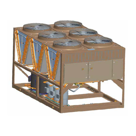
FORM 150.73-NM1 SECTION 2 – PRODUCT DESCRIPTION ISSUE DATE: 09/04/2020 UNIT COMPONENTS FAN ASSEMBLIES CONTROL PANEL COMPRESSORS CONDENSER COILS POWER PANEL FIGURE 2 - UNIT COMPONENTS FRONT JOHNSON CONTROLS... -
Page 21: Figure 3 - Power Panel Components
FORM 150.73-NM1 SECTION 2 – PRODUCT DESCRIPTION ISSUE DATE: 09/04/2020 DISCONNECT SWITCH FAN FUSES FAN CONTACTORS FAN CONTACTOR COMPRESSOR OVERLOADS XTBF1 COMPRESSOR CONTACTORS LD13247 FIGURE 3 - POWER PANEL COMPONENTS JOHNSON CONTROLS... -
Page 22: Figure 4 - Power Panel / Control Components
FORM 150.73-NM1 SECTION 2 – PRODUCT DESCRIPTION ISSUE DATE: 09/04/2020 FAN FUSES MICROCOMPUTER CONTROL FAN CONTACTORS CONTROL RELAY CENTER MICROPANEL DISPLAY KEYPAD COMPRESSOR OVERLOADS XTBC1 MICROBOARD XTBC2 COMPRESSOR XTBF2 CONTACTORS LD13248 FIGURE 4 - POWER PANEL / CONTROL COMPONENTS JOHNSON CONTROLS... -
Page 23: Nomenclature (Pin)
FORM 150.73-NM1 SECTION 2 – PRODUCT DESCRIPTION ISSUE DATE: 09/04/2020 NOMENCLATURE (PIN) Basic Unit 0148 Design Series YC=York Scroll Type Start X=Across-the-Line Voltage Code Unit 17=200-3-60 28=230-3-60 40=380-3-60 Condensing 46=460-3-60 58=575-3-60 Refrigerant Nominal Capacity E= R-410A Z= Standard Efficiency Unit... - Page 24 FORM 150.73-NM1 SECTION 2 – PRODUCT DESCRIPTION ISSUE DATE: 09/04/2020 PRODUCT IDENTIFICATION NUMBER (PIN) (CON’T) FEATURE FEATURE DESCRIPTION OPTION OPTION DESCRIPTION High Efficiency Standard Efficiency UNIT Unit Designator (PIN 9) High Efficiency (Round Tube) Standard Efficiency (Round Tube) Refrigerant (PIN 10) R-410A 200/3/60 230/3/60...
- Page 25 FORM 150.73-NM1 SECTION 2 – PRODUCT DESCRIPTION ISSUE DATE: 09/04/2020 PRODUCT IDENTIFICATION NUMBER (PIN) (CON’T) FEATURE FEATURE DESCRIPTION OPTION OPTION DESCRIPTION No Chicago Code Kit required Both Chicago Code and Serv Isolation CHICAGO Chicago Code Kit (PIN 31) Chicago Code Kit required Service Isolation Valves Special Chicago Code Kit required Standard Valves Req’d...
- Page 26 FORM 150.73-NM1 SECTION 2 – PRODUCT DESCRIPTION ISSUE DATE: 09/04/2020 PRODUCT IDENTIFICATION NUMBER (PIN) (CON’T) FEATURE FEATURE DESCRIPTION OPTION OPTION DESCRIPTION No Enclosure required Wire (Full Unit) Encl Panels (factory) Wire (Full Unit) Encl Panels (field) Wire/Louvered Encl Panels (factory) Wire/Louvered Encl Panels (field) Louvered (Cond only) Encl Panels (factory) ENCL...
-
Page 27: Refrigerant Flow Diagram
FORM 150.73-NM1 SECTION 2 – PRODUCT DESCRIPTION ISSUE DATE: 09/04/2020 REFRIGERANT FLOW DIAGRAM LD04284A FIGURE 5 - REFRIGERANT FLOW DIAGRAM JOHNSON CONTROLS... -
Page 28: Process And Instrumentation Diagram
FORM 150.73-NM1 SECTION 2 – PRODUCT DESCRIPTION ISSUE DATE: 09/04/2020 PROCESS AND INSTRUMENTATION DIAGRAM Control Functions: DV - Displa y Value Fans Fans Components: CHT - Chilled Liquid Temperature HPC - High Pressure Cutout Pressure Relief Valve LPC - Low Pressure Cutout HPL - High Pressure Load Limiting Ser vice (Ball) Valve LTC - Low Temperature Cutout... -
Page 29: Section 3 - Handling And Storage
FORM 150.73-NM1 ISSUE DATE: 09/04/2020 SECTION 3 – HANDLING AND STORAGE DELIVERY AND STORAGE UNIT RIGGING To ensure consistent quality and maximum reliability, Use spreader bars to avoid lifting chains hitting the all units are tested and inspected before leaving the fac- unit. - Page 30 FORM 150.73-NM1 SECTION 3 – HANDLING AND STORAGE ISSUE DATE: 09/04/2020 Moving the Condensing Unit Lifting Weights Prior to moving the unit, ensure that the installation For details of weights and weight distribution, refer to site is suitable for installing the unit and is easily ca- the data shipped in the unit information packet and unit pable of supporting the weight of the unit and all as- nameplate.
-
Page 31: Section 4 - Installation
FORM 150.73-NM1 ISSUE DATE: 09/04/2020 SECTION 4 – INSTALLATION To ensure warranty coverage, this equip- ensure adequate supply of fresh air for the condenser. ment must be commissioned and serviced The units must be installed with sufficient clearances by an authorized Johnson Controls for air entrance to the condenser coil, for air discharge service mechanic or a qualified service away from the condenser, and for servicing access. -
Page 32: Spring Isolators (Optional)
The following ductwork recommendations are intend- in the YORK Engineering Guide for the specific con- ed to ensure satisfactory operation of the unit. Failure densing unit model. Sound blankets for the compres- to follow these recommendations could cause damage sors and low sound fans are available. -
Page 33: Compressor Heaters
FORM 150.73-NM1 SECTION 4 – INSTALLATION ISSUE DATE: 09/04/2020 Copper power wiring only should be used for supply- ELECTRICAL WIRING ing power to the unit. This is recommended to avoid Field Wiring safety and reliability issues resulting from connection failure at the power connections to the unit. Aluminum Power wiring must be provided through a fused dis- wiring is not recommended due to thermal character- connect switch to the unit terminals (or optional mold-... - Page 34 FORM 150.73-NM1 SECTION 4 – INSTALLATION ISSUE DATE: 09/04/2020 See Air Proving Switch/Remote Start-Stop Evaporator Blower Start Contacts Contacts. For constant fan operation: Terminal block XTBC2 - terminals 23 to 24, are normally open contacts that can be used to switch field supplied power to provide a start signal to the evaporator blower contactor.
-
Page 35: Compressor Heaters
LEMS, OR LACK OF OIL RETURN. For more details, refer to ASHRAE Refrigeration Filter driers and sight glasses are shipped loose for field Handbook, Chapter 2 and YORK DX Piping Guide installation on each refrigerant circuit. Field refrigerant Form 050.40-ES2. -
Page 36: Table 1 - Fitting Equivalent Lengths
FORM 150.73-NM1 SECTION 4 – INSTALLATION ISSUE DATE: 09/04/2020 TABLE 1 - FITTING EQUIVALENT LENGTHS *COPPER FITTING EQUIVALENT LENGTHS LINE SIZE O.D. SHORT-RADIUS ELL LONG-RADIUS ELL 3/4 in. (19 mm) 6.5 ft. (2 m) 4.5 ft. (1.4 m) 7/8 in. (22 mm) 7.8 ft. -
Page 37: Table 4 - Refrigerant Line Connections
7/8 in. for the optional factory mounted hot gas bypass valve. Note: Hot gas bypass is only available for refrigerant system number 1. 7. For more information, refer to either the YORK DX Piping Guide (Form 050.40-ES2) or the ASHRAE Refrigeration Handbook. -
Page 38: Oil Traps
FORM 150.73-NM1 SECTION 4 – INSTALLATION ISSUE DATE: 09/04/2020 Refrigerant Line Sizing Condenser Below Evaporator Refrigerant piping systems must be designed to pro- When the condensing unit is located below the evapo- vide practical line sizes without excessive pressure rator, the liquid line must be designed for both friction drops, prevent compressor oil from being “trapped”... -
Page 39: Refrigerant Piping Notes
FORM 150.73-NM1 SECTION 4 – INSTALLATION ISSUE DATE: 09/04/2020 TABLE 5 - REFRIGERANT LINE PRESSURE DROPS (ENGLISH) SUCTION LINE LIQUID LINE VELOCITY MODEL SYSTEM NOMINAL COPPER PRESSURE NOMINAL COPPER PRESSURE @ NOMINAL NUMBER NUMBER TONS TYPE L DROP TONS TYPE L DROP CAPACITY INCHES OD... -
Page 40: Figure 8 - Single-Point Supply Connection - Terminal Block, Non-Fused Disconnect Switch
FORM 150.73-NM1 SECTION 4 – INSTALLATION ISSUE DATE: 09/04/2020 Power Panel Power Panel Power Panel Control Panel Control Panel Control Panel Terminal Block, Terminal Block, MICROPANEL MICROPANEL NF Disconnect SW NF Disconnect SW or Circuit Breaker or Circuit Breaker CTB2 CTB2 CTB2 Flow Switch... -
Page 41: Control Wiring
FORM 150.73-NM1 SECTION 4 – INSTALLATION ISSUE DATE: 09/04/2020 CONTROL WIRING PWM INPUT (CAN ONLY BE USED WITH DISCHARGE AIR TEMP CONTROL) LOAD LIMIT INPUT AIR PROVING SWITCH (DISCHARGE AIR TEMP CONTROL AND SUCTION PRESSURE CONTROL) AND REMOTE START/STOP SYSTEM 1 THERMOSTAT (SUCTION PRESSURE CONTROL ONLY) (JUMPER FOR DISCHARGE AIR TEMP CONTROL) SYSTEM 2 THERMOSTAT (SUCTION PRESSURE CONTROL ONLY) XTBC1... - Page 42 FORM 150.73-NM1 ISSUE DATE: 09/04/2020 THIS PAGE INTENTIONALLY LEFT BLANK. JOHNSON CONTROLS...
-
Page 43: Section 5 - Technical Data
FORM 150.73-NM1 ISSUE DATE: 09/04/2020 SECTION 5 – TECHNICAL DATA OPERATIONAL LIMITATIONS (ENGLISH) Voltage Limitations The following voltage limitations are absolute and Temperature and Flows operation beyond these limitations may cause serious Excessive flow will cause damage to the damage to the compressor. cooler. -
Page 44: Physical Data (English)
FORM 150.73-NM1 SECTION 5 – TECHNICAL DATA ISSUE DATE: 09/04/2020 PHYSICAL DATA (ENGLISH) YLUA0078_ – YLUA0158_ 60HZ TABLE 7 - PHYSICAL DATA (ENGLISH) REFRIGERANT R-410A MODEL NUMBER YLUA - STANDARD EFFIECY UNITS GENERAL UNIT DATA 0078ZE 0088ZE 0095ZE 0098ZE 0108ZE 0130ZE 0148ZE 0158ZE... -
Page 45: Table 8 - Micro Panel Power Supply
FORM 150.73-NM1 SECTION 5 – TECHNICAL DATA ISSUE DATE: 09/04/2020 Electrical Data TABLE 8 - MICRO PANEL POWER SUPPLY OVER CURRENT PROTECTION, CONTROL UNIT VOLTAGE POWER SEE NOTE B NF DISC SW UNIT NOTE A MODELS W/O VOLTAGE MINIMUM MAXIMUM CONTROL 115-1-60/50 TRANS... -
Page 46: Table 10 - Standard Efficiency Unit Electrical Data (4 Compr)
FORM 150.73-NM1 SECTION 5 – TECHNICAL DATA ISSUE DATE: 09/04/2020 ELECTRICAL DATA SINGLE POINT TABLE 10 - STANDARD EFFICIENCY UNIT ELECTRICAL DATA (4 COMPR) SYSTEM # 1 DUAL COMPR 1 COMPR 2 PUMP VOLT PUMP DUAL ELEM MODEL EFF. MODEL CODE ELEM FUSE... - Page 47 FORM 150.73-NM1 SECTION 5 – TECHNICAL DATA ISSUE DATE: 09/04/2020 SINGLE POINT SYSTEM # 1 SYSTEM # 2 COMPR 3 COMPR 1 COMPR 2 COMPR 3 44.0 44.0 37.0 37.0 23.1 23.1 19.0 19.0 15.3 15.3 SYSTEM # 1 SYSTEM # 2 COMPR 3 COMPR 1 COMPR 2...
-
Page 48: Table 12 - Standard Efficiency Unit Electrical Data (6 Compr)
FORM 150.73-NM1 SECTION 5 – TECHNICAL DATA ISSUE DATE: 09/04/2020 SINGLE POINT TABLE 12 - STANDARD EFFICIENCY UNIT ELECTRICAL DATA (6 COMPR) SYSTEM # 1 DUAL COMPR 1 COMPR 2 Pump Volt Pump DUAL ELEM MODEL Eff. Model Code N/F DS ELEM FUSE FUSE... - Page 49 FORM 150.73-NM1 SECTION 5 – TECHNICAL DATA ISSUE DATE: 09/04/2020 SINGLE POINT SYSTEM # 1 SYSTEM # 2 COMPR 3 COMPR 1 COMPR 2 COMPR 3 44.0 44.0 37.0 37.0 23.1 23.1 19.0 19.0 15.3 15.3 44.0 44.0 37.0 37.0 23.1 23.1 19.0...
-
Page 50: Table 15 - Standard Efficiency Unit Electrical Data (4 Compr)
FORM 150.73-NM1 SECTION 5 – TECHNICAL DATA ISSUE DATE: 09/04/2020 DUAL POINT TABLE 15 - STANDARD EFFICIENCY UNIT ELECTRICAL DATA (4 COMPR) System 1 System 2 VOLT DUAL DUAL DUAL DUAL MODEL EFF MIN N/ MIN N/F Code ELEM ELEM ELEM ELEM FUSE and... - Page 51 FORM 150.73-NM1 SECTION 5 – TECHNICAL DATA ISSUE DATE: 09/04/2020 DUAL POINT SYSTEM # 1 SYSTEM # 2 COMPR 1 COMPR 2 COMPR 3 COND FANS COMPR 1 COMPR 2 COMPR 3 COND FANS RLA LRA RLA LRA RLA LRA QTY LRA RLA LRA RLA LRA RLA LRA QTY 44.0 44.0...
-
Page 52: Table 17 - Standard Efficiency Unit Electrical Data (6 Compr)
FORM 150.73-NM1 SECTION 5 – TECHNICAL DATA ISSUE DATE: 09/04/2020 DUAL POINT TABLE 17 - STANDARD EFFICIENCY UNIT ELECTRICAL DATA (6 COMPR) System 1 System 2 VOLT DUAL DUAL DUAL DUAL MODEL EFF MIN N/ MIN N/F Code ELEM ELEM ELEM ELEM FUSE and... - Page 53 FORM 150.73-NM1 SECTION 5 – TECHNICAL DATA ISSUE DATE: 09/04/2020 DUAL POINT SYSTEM # 1 SYSTEM # 2 COMPR 1 COMPR 2 COMPR 3 COND FANS COMPR 1 COMPR 2 COMPR 3 COND FANS RLA LRA RLA LRA RLA LRA QTY LRA RLA LRA RLA LRA RLA LRA QTY 44.0 44.0...
-
Page 54: Table 20 - Lug Sizing
FORM 150.73-NM1 SECTION 5 – TECHNICAL DATA ISSUE DATE: 09/04/2020 TABLE 20 - LUG SIZING NON-FUSE DISC SW. CIRCUIT BREAKER TERMINAL BLOCK MODEL RATING SIZE RATING SIZE S6-600 S6: (2) 250kcmil - 500kcmil S5-400 S5: (2) 3/0 - 250kcmil (4) 4AWG - 500kcmil S6-600 S6: (2) 250kcmil - 500kcmil S5-400... - Page 55 FORM 150.73-NM1 SECTION 5 – TECHNICAL DATA ISSUE DATE: 09/04/2020 of the rated load amps for all other loads includ- Electrical Notes ed in the circuit. Otherwise, HACR-type circuit 1. Minimum Circuit Ampacity (MCA) is based on breakers must be used. Maximum HACR circuit 125% of the rated load amps for the largest mo- breaker rating is based on 225% of the rated load tor plus 100% of the rated load amps for all other...
- Page 56 Note Well {See Note} - KM Suppressor) Wiring And Items Shown Thus Are - KCR Control Relay Standard York Accessories Pump Contactor Part Wiring And Items Shown Thus Are Not - KP (Including Coil Suppressor) Supplied By York - KT...
- Page 57 All sources of supply shown on this diagram to be taken from one main isolator, not shown or supplied by YORK. Green and yellow wire is used for earth, multi-colored cable used for low voltage. Red wire used for AC Control, blue wire for neutral, black wire for AC and DC power.
- Page 58 FORM 150.73-NM1 SECTION 5 – TECHNICAL DATA ISSUE DATE: 09/04/2020 Electrical Notes And Legend (Continued) GENERAL For optional hydro kit. Heater -EPH is fitted and wired as shown. On single pump -KP1, -QMMSP1 and -MP1 are fitted and wired as shown. On two pump hydro kits -KP2, -QMMSP2 and -MP2 are also fitted and wired as shown. Current measurement option wired as show.
- Page 59 FORM 150.73-NM1 SECTION 5 – TECHNICAL DATA ISSUE DATE: 09/04/2020 THIS PAGE INTENTIONALLY LEFT BLANK. JOHNSON CONTROLS...
-
Page 60: Wiring Diagrams
FORM 150.73-NM1 SECTION 5 – TECHNICAL DATA ISSUE DATE: 09/04/2020 WIRING DIAGRAMS Elementary Wiring Diagrams 035-21583-101 REV D FIGURE 11 - ELEMENTARY WIRING DIAGRAM JOHNSON CONTROLS... - Page 61 FORM 150.73-NM1 SECTION 5 – TECHNICAL DATA ISSUE DATE: 09/04/2020 FIGURE 11 - ELEMENTARY WIRING DIAGRAM (CONT’D) JOHNSON CONTROLS...
- Page 62 FORM 150.73-NM1 SECTION 5 – TECHNICAL DATA ISSUE DATE: 09/04/2020 035-21583-102 REVD FIGURE 11 - ELEMENTARY WIRING DIAGRAM (CONT’D) JOHNSON CONTROLS...
- Page 63 FORM 150.73-NM1 SECTION 5 – TECHNICAL DATA ISSUE DATE: 09/04/2020 FIGURE 11 - ELEMENTARY WIRING DIAGRAM (CONT’D) JOHNSON CONTROLS...
- Page 64 FORM 150.73-NM1 SECTION 5 – TECHNICAL DATA ISSUE DATE: 09/04/2020 FIGURE 11 - ELEMENTARY WIRING DIAGRAM (CONT’D) JOHNSON CONTROLS...
- Page 65 FORM 150.73-NM1 SECTION 5 – TECHNICAL DATA ISSUE DATE: 09/04/2020 FIGURE 11 - ELEMENTARY WIRING DIAGRAM (CONT’D) JOHNSON CONTROLS...
- Page 66 FORM 150.73-NM1 SECTION 5 – TECHNICAL DATA ISSUE DATE: 09/04/2020 035-21589-107 REV A FIGURE 11 - ELEMENTARY WIRING DIAGRAM (CONT’D) JOHNSON CONTROLS...
- Page 67 FORM 150.73-NM1 SECTION 5 – TECHNICAL DATA ISSUE DATE: 09/04/2020 FIGURE 11 - ELEMENTARY WIRING DIAGRAM (CONT’D) JOHNSON CONTROLS...
- Page 68 FORM 150.73-NM1 SECTION 5 – TECHNICAL DATA ISSUE DATE: 09/04/2020 035-21589-106 REVE FIGURE 11 - ELEMENTARY WIRING DIAGRAM (CONT’D) JOHNSON CONTROLS...
- Page 69 FORM 150.73-NM1 SECTION 5 – TECHNICAL DATA ISSUE DATE: 09/04/2020 FIGURE 11 - ELEMENTARY WIRING DIAGRAM (CONT’D) JOHNSON CONTROLS...
-
Page 70: Figure 12 - Power Options Connection Diagram
FORM 150.73-NM1 SECTION 5 – TECHNICAL DATA ISSUE DATE: 09/04/2020 Power Options Connection Diagram 035-21589-103 REVB LD13234A FIGURE 12 - POWER OPTIONS CONNECTION DIAGRAM JOHNSON CONTROLS... - Page 71 FORM 150.73-NM1 SECTION 5 – TECHNICAL DATA ISSUE DATE: 09/04/2020 LD13901 FIGURE 12 - POWER OPTIONS CONNECTION DIAGRAM (CONT’D) JOHNSON CONTROLS...
- Page 72 FORM 150.73-NM1 SECTION 5 – TECHNICAL DATA ISSUE DATE: 09/04/2020 035-21589-101 REVC FIGURE 12 - POWER OPTIONS CONNECTION DIAGRAM (CONT’D) JOHNSON CONTROLS...
- Page 73 FORM 150.73-NM1 SECTION 5 – TECHNICAL DATA ISSUE DATE: 09/04/2020 FIGURE 12 - POWER OPTIONS CONNECTION DIAGRAM (CONT’D) JOHNSON CONTROLS...
-
Page 74: Figure 13 - Single Point And Dual Point Wiring
FORM 150.73-NM1 SECTION 5 – TECHNICAL DATA ISSUE DATE: 09/04/2020 035-21583-116_rev - FIGURE 13 - SINGLE POINT AND DUAL POINT WIRING JOHNSON CONTROLS... - Page 75 FORM 150.73-NM1 SECTION 5 – TECHNICAL DATA ISSUE DATE: 09/04/2020 THIS PAGE INTENTIONALLY LEFT BLANK. JOHNSON CONTROLS...
-
Page 76: Figure 14 - Wiring
FORM 150.73-NM1 SECTION 5 – TECHNICAL DATA ISSUE DATE: 09/04/2020 Wiring 035-21583-106 REVA LD13238 FIGURE 14 - WIRING JOHNSON CONTROLS... - Page 77 FORM 150.73-NM1 SECTION 5 – TECHNICAL DATA ISSUE DATE: 09/04/2020 LD13239 FIGURE 14 - WIRING (CONT’D) JOHNSON CONTROLS...
-
Page 78: Figure 15 - Micro Panel Connections
FORM 150.73-NM1 SECTION 5 – TECHNICAL DATA ISSUE DATE: 09/04/2020 Micro Panel Connections 035-21589-102 REVD FIGURE 15 - MICRO PANEL CONNECTIONS JOHNSON CONTROLS... - Page 79 FORM 150.73-NM1 SECTION 5 – TECHNICAL DATA ISSUE DATE: 09/04/2020 FIGURE 15 - MICRO PANEL CONNECTIONS (CONT’D) JOHNSON CONTROLS...
-
Page 80: Figure 16 - Elementary Diagram
FORM 150.73-NM1 SECTION 5 – TECHNICAL DATA ISSUE DATE: 09/04/2020 035-21583-103 REV. B LD13992A FIGURE 16 - ELEMENTARY DIAGRAM JOHNSON CONTROLS... - Page 81 FORM 150.73-NM1 SECTION 5 – TECHNICAL DATA ISSUE DATE: 09/04/2020 LD13993A FIGURE 16 - ELEMENTARY DIAGRAM (CONT’D) JOHNSON CONTROLS...
- Page 82 FORM 150.73-NM1 SECTION 5 – TECHNICAL DATA ISSUE DATE: 09/04/2020 035-21589-105 REVA FIGURE 16 - ELEMENTARY DIAGRAM (CONT’D) JOHNSON CONTROLS...
- Page 83 FORM 150.73-NM1 SECTION 5 – TECHNICAL DATA ISSUE DATE: 09/04/2020 FIGURE 16 - ELEMENTARY DIAGRAM (CONT’D) JOHNSON CONTROLS...
-
Page 84: Dimensions (English)
FORM 150.73-NM1 SECTION 5 – TECHNICAL DATA ISSUE DATE: 09/04/2020 DIMENSIONS (ENGLISH) DIMENSIONS – YLUA0078 TO 0095 (ENGLISH) CONNECTION SYSTEM 1 SYSTEM 2 LENGTH WIDTH HEIGHT SIZES DIMENSIONS DIMENSIONS MODEL SUCTION LIQUID SUCTION LIQUID SUCTION LIQUID IN 1/2 OUT 1/2 YLUA0078ZE 116.1... - Page 85 FORM 150.73-NM1 SECTION 5 – TECHNICAL DATA ISSUE DATE: 09/04/2020 DIMENSIONS – YLUA0098 TO 0130 (ENGLISH) 5/8 in. dia. mounting holes (typ) Top view L1-OUT S1-IN S2-IN L2-OUT Front view Side view LD19671a CONNECTION SYSTEM 1 SYSTEM 2 LENGTH WIDTH HEIGHT SIZES DIMENSIONS DIMENSIONS...
- Page 86 FORM 150.73-NM1 SECTION 5 – TECHNICAL DATA ISSUE DATE: 09/04/2020 DIMENSIONS – YLUA0148 TO 0158 (ENGLISH) CONNECTION SYSTEM 1 SYSTEM 2 LENGTH WIDTH HEIGHT SIZES DIMENSIONS DIMENSIONS MODEL SUCTION LIQUID SUCTION LIQUID SUCTION LIQUID IN 1/2 OUT 1/2 YLUA0148ZE 187.5 88.3 95.3 89.7 43.9...
-
Page 87: Clearances
FORM 150.73-NM1 SECTION 5 – TECHNICAL DATA ISSUE DATE: 09/04/2020 CLEARANCES (2 m) (1.3 m) LD13243 NOTES: 1. No obstructions allowed above the unit. 2. Only one adjacent wall may be higher than the unit. 3. Adjacent units should be 10 ft (3 m) apart. FIGURE 17 - UNIT CLEARANCES –... -
Page 88: Weight Distribution And Isolator Mounting Positions
FORM 150.73-NM1 SECTION 5 – TECHNICAL DATA ISSUE DATE: 09/04/2020 WEIGHT DISTRIBUTION AND ISOLATOR MOUNTING POSITIONS General and on the following page. The drawing will show the isolator locations along with the weight in pounds and Weights of specific chiller models vary significantly as kilograms at the specific location, isolator position, options are added. -
Page 89: Isolator Information
FORM 150.73-NM1 SECTION 5 – TECHNICAL DATA ISSUE DATE: 09/04/2020 ISOLATOR INFORMATION One Inch Deflection Spring Isolator Cross-Reference 5/8" Ø1/2" H" C" T" B" L" D" W" LD13759A MOUNT DIMENSION DATA (INCHES) TYPE 7-3/4 6-1/2 4-3/4 5-5/8 10-1/2 9-1/4 7-3/4 9/16 RATED CAPACITY (FOR UNITS WITH ALL LOAD POINTS LESS THAN 1785 LB (810 KG) - Page 90 FORM 150.73-NM1 SECTION 5 – TECHNICAL DATA ISSUE DATE: 09/04/2020 One Inch Deflection Spring Isolators Installation Instructions 1. Read instructions in their entirety before begin- 6. The adjustment process can only begin after the equipment or machine is at its full operating ning installation.
- Page 91 FORM 150.73-NM1 SECTION 5 – TECHNICAL DATA ISSUE DATE: 09/04/2020 Two Inch Deflection Seismic Isolator Cross-Reference Y2RS 1-1/8" 5" 5/8" 2-3/4" 2-3/4" 12" 3/8" GAP 5/8-11UNC Ø3/4" TYP. (4) TYP.(4) 3/4" 7/8" 1/2" LIMIT STOP and 8-3/8" OPER. HEIGHT 12-1/4" 14"...
- Page 92 FORM 150.73-NM1 SECTION 5 – TECHNICAL DATA ISSUE DATE: 09/04/2020 Seismic Isolator Installation and Adjustment 1. Read instructions in their entirety before begin- with a minimum 3/8 fillet welds 2 in. long at 3 in. ning installation. o.C. For a minimum total weld of 10 in. (All sides of equipment or bracket resting on top plate ("a") 2.
- Page 93 FORM 150.73-NM1 SECTION 5 – TECHNICAL DATA ISSUE DATE: 09/04/2020 Durulene Isolator Cross-Reference RD-Style Isolators MOLDED DURULENE ø D THRU TYP 2 PLACES Notes: 1. All dimensions are inches, interpreted per ANSI Y14. 2. See the following page for installation instructions. 3.
- Page 94 FORM 150.73-NM1 SECTION 5 – TECHNICAL DATA ISSUE DATE: 09/04/2020 Installation of Durulene Vibration Isolators 1. Read instructions in their entirety before begin- 4. Bolt or anchor all isolators to supporting structure ning installation. utilizing base Thru holes ("b"). 2. Isolators are shipped fully assembled and are to 5.
-
Page 95: Section 6 - Commissioning
COMMISSIONING Compressor Oil Commissioning of this unit should only To add oil to a circuit - connect a YORK hand oil pump be carried out by Johnson Controls Au- (Part No. 470-10654-000) to the 1/4 in. oil charging thorized personnel. -
Page 96: Preparation - Power On
FORM 150.73-NM1 SECTION 6 – COMMISSIONING ISSUE DATE: 09/04/2020 PREPARATION – POWER ON Switch Settings Perform the commissioning using the Ensure that the condensing unit OFF/ON UNIT switch detailed checks outlined in the EQUIP- at the bottom of the keypad is OFF. Place the optional MENT PRE-STARTUP and STARTUP circuit breaker handle on the panel door to ON. - Page 97 FORM 150.73-NM1 SECTION 6 – COMMISSIONING ISSUE DATE: 09/04/2020 NEW RELEASE Form 150.73-CL2 (1012) YLUA INSTALLATION AND START-UP CHECKLIST CUSTOMER: _________________________________ JOB NAME: _________________________________ ADDRESS: __________________________________ LOCATION: _________________________________ PHONE: _____________________________________ CUSTOMER ORDER NO: ______________________ JCI TEL NO: ____________________ JCI ORDER NO: ________________ JCI CONTRACT NO: ____________ CHILLER MODEL NO: ____________________________ UNIT SERIAL NO: ___________________________ ___________...
- Page 98 FORM 150.73-CL2 FORM 150.73-NM1 ISSUE DATE: 10/29/2012 SECTION 6 – COMMISSIONING ISSUE DATE: 09/04/2020 3. Program/verify the Cooling Setpoints, Program 4. Put the unit into Service Mode (as described Setpoints, and unit Options. Record the values under the Control Service and Troubleshooting below.
- Page 99 P.O. Box 1592, York, Pennsylvania USA 17405-1592 800-861-1001 Subject to change without notice. Printed in USA Copyright © by Johnson Controls 2012 www.johnsoncontrols.com...
- Page 100 FORM 150.73-NM1 ISSUE DATE: 09/04/2020 THIS PAGE INTENTIONALLY LEFT BLANK. JOHNSON CONTROLS...
-
Page 101: Section 7 - Unit Controls
YORK MILLENNIUM CONTROL CENTER 00065VIP INTRODUCTION MICROPROCESSOR BOARD The YORK MicroComputer Control Center is a mi- The Microprocessor Board is the controller and deci- croprocessor based control system designed to provide sion maker in the control panel. System inputs such the entire control for the condensing unit. -
Page 102: Unit Switch
FORM 150.73-NM1 SECTION 7 – UNIT CONTROLS ISSUE DATE: 09/04/2020 UNIT SWITCH BATTERY BACK-UP A unit ON/OFF switch is just underneath the keypad. The Microprocessor Board contains a Real Time Clock This switch allows the operator to turn the entire unit integrated circuit chip with an internal battery backup. -
Page 103: Status Key
FORM 150.73-NM1 SECTION 7 – UNIT CONTROLS ISSUE DATE: 09/04/2020 STATUS KEY 00066VIP Unit Status F L O W S W I T C H / R E M S T O P Pressing the STATUS key will enable the operator to R U N P E R M determine current unit operating status. - Page 104 FORM 150.73-NM1 SECTION 7 – UNIT CONTROLS ISSUE DATE: 09/04/2020 that limits the loading of a system when the suction S Y S T I M E R pressure drops to within 15% above the suction pres- S Y S T I M E R sure cutout.
- Page 105 FORM 150.73-NM1 SECTION 7 – UNIT CONTROLS ISSUE DATE: 09/04/2020 System safeties are faults that cause the individual sys- This cutout is completely ignored for the first 30 sec- tem to be shut down. Unit safeties are faults that cause onds of system run time to avoid nuisance shutdowns, all running compressors to be shut down.
- Page 106 FORM 150.73-NM1 SECTION 7 – UNIT CONTROLS ISSUE DATE: 09/04/2020 Whenever the motor protector or discharge sensor unit. Restart is allowed after the unit is fully powered shuts down a compressor and the system, the inter- again and the anti-recycle timers have finished count- nal compressor contacts will open for a period of 30 ing down.
-
Page 107: Figure 19 - Status Key Messages Quick Reference List
FORM 150.73-NM1 SECTION 7 – UNIT CONTROLS ISSUE DATE: 09/04/2020 STATUS KEY MESSAGES STATUS KEY MESSAGES General Messages Fault Messages System Safeties Unit Safeties Unit Warnings Unit Switch Off Shutdown Remote Controlled System X High Disch Pressure Low Ambient Temp Low Battery Shutdown Daily Schedule... -
Page 108: Display/Print Keys
FORM 150.73-NM1 SECTION 7 – UNIT CONTROLS ISSUE DATE: 09/04/2020 DISPLAY/PRINT KEYS 00067VIP The Display/Print keys allow the user to retrieve sys- able under the Oper Data key in the order that they are tem and unit information that is useful for monitoring displayed. - Page 109 FORM 150.73-NM1 SECTION 7 – UNIT CONTROLS ISSUE DATE: 09/04/2020 S Y S 7 2 . 1 P S I G L O A D T I M E R S E C = 2 2 7 . 0 P S I G U N L O A D T I M E R S E C...
- Page 110 ISN. The second message indicates the system run time in ISN – York Talk via ISN allows remote load limit- days – hours – minutes – seconds. Please note that this ing and temperature reset through an ISN system.
-
Page 111: Figure 20 - Operation Data
System 2 Discharge and Suction Pressure Operating Data printout is shown below. (Note: Not all values are printed for all models.) *System X Accumulated Hours YORK INTERNATIONAL CORPORATION *System X Accumulated Starts MILLENNIUM CONDENSING UNIT UNIT STATUS Load and Unload Timers... - Page 112 The difference is that the Daily Schedule is not See Service And Troubleshooting section printed in the history print and the header will be as for Printer Installation information. follows. YORK INTERNATIONAL CORPORATION MILLENNIUM CONDENSING UNIT SAFETY SHUTDOWN NUMBER 1 SHUTDOWN @ 3:56PM 29 JAN 08...
- Page 113 FORM 150.73-NM1 SECTION 7 – UNIT CONTROLS ISSUE DATE: 09/04/2020 History Displays L O C A L / R E M O T E M O D E The HISTORY key gives the user access to many unit X X X X X X X X X and system operating parameters at the time of a unit or system safety shutdown.
- Page 114 FORM 150.73-NM1 SECTION 7 – UNIT CONTROLS ISSUE DATE: 09/04/2020 S Y S X X X X P S I G S U C T I O N P R E S S U R E R A N G E + / - X X X P S I G C U T O U T...
- Page 115 FORM 150.73-NM1 SECTION 7 – UNIT CONTROLS ISSUE DATE: 09/04/2020 Displays for System 1 starting with SYS X NUMBER S Y S X X X X P S I G OF COMPS RUNNING X through SYS X AMPS = X X X X P S I G XXX.X VOLTS = X.X will be displayed first, fol- lowed by displays for System 2.
-
Page 116: Entry Keys
FORM 150.73-NM1 SECTION 7 – UNIT CONTROLS ISSUE DATE: 09/04/2020 ENTRY KEYS 00068VIP The Entry Keys allows the user to view, change pro- Enter/adv Key grammed values. The ENTRY keys consist of an ↑ The ENTER/ADV key must be pushed after any change (UP) arrow key, ↓... -
Page 117: Setpoints Keys
FORM 150.73-NM1 SECTION 7 – UNIT CONTROLS ISSUE DATE: 09/04/2020 SETPOINTS KEYS 00069VIP Programming of the cooling setpoints, daily schedule, Following are the four possible messages that can be and safeties is accomplished by using the keys located displayed after pressing the COOLING SETPOINT under the SETPOINTS section. - Page 118 FORM 150.73-NM1 SECTION 7 – UNIT CONTROLS ISSUE DATE: 09/04/2020 such as an ISN control. The message also indicates that in Suction Pressure Control are the suction pressures the control point is based on Discharge Air Tempera- of each individual system on the condensing Unit and ture leaving the evaporator.
- Page 119 FORM 150.73-NM1 SECTION 7 – UNIT CONTROLS ISSUE DATE: 09/04/2020 As with the other setpoints, the Up Arrow and Down After SUN (Sunday) schedule appears on the display Arrow keys are used to change the Temp Reset value. a subsequent press of the SCHEDULE/ADVANCE After using the UP and DOWN ARROWS to adjust DAY key will display the Holiday schedule.
- Page 120 FORM 150.73-NM1 SECTION 7 – UNIT CONTROLS ISSUE DATE: 09/04/2020 chanical high pressure switch located in the refrigerant has timed out. If the lead system has run for less than 5 circuit. The system can restart when the discharge pres- minutes, 3 times in a row, the anti-recycle timer will be sure drops 40 psig (2.76 barg) below the cutout point.
- Page 121 XTBC1. If the jumper on 460 VAC units: is not installed, which is the correct con- figuration for YLUA0078 and 0158 units, • Add the sum of the compressor and fan RLA’s in the system the unit will act as a 2-system unit. The jumper is only checked by the micro at •...
-
Page 122: Table 21 - Cooling Setpoints Programmable Limits And Defaults
FORM 150.73-NM1 SECTION 7 – UNIT CONTROLS ISSUE DATE: 09/04/2020 TABLE 21 - COOLING SETPOINTS PROGRAMMABLE LIMITS AND DEFAULTS SETPOINT VALUE LOW LIMIT HIGH LIMIT DEFAULT 45.0 °F 70.0°F 44.0°F Discharge Air Temp. Setpoint 7.2°C 21.1°C 12.7°C 3.0°F 10.0°F 5.0°F Discharge Air Temp. -
Page 123: Figure 21 - Setpoints Quick Reference List
FORM 150.73-NM1 SECTION 7 – UNIT CONTROLS ISSUE DATE: 09/04/2020 Oper Data Quick Reference List This table provides a quick reference of the setpoints list for the Setpoints Keys. SETPOINTS KEYS Cooling Setpoints Key Schedule/ Program Mode (press key to adv.) Advance Day Key (press enter to adv.) Local/Remote Discharge... -
Page 124: Unit Keys
FORM 150.73-NM1 SECTION 7 – UNIT CONTROLS ISSUE DATE: 09/04/2020 UNIT KEYS OPTIONS CLOCK 00070VIP Options Key S Y S S W I T C H O F F There are many user programmable options under the S Y S S W I T C H OPTIONS key. - Page 125 FORM 150.73-NM1 SECTION 7 – UNIT CONTROLS ISSUE DATE: 09/04/2020 The software may skip the low ambient D I S P L A Y U N I T S selection, but a low ambient kit is still needed to operate below 25°F. This mode displays system operating values in Scien- tific International Units of °C or barg.
- Page 126 FORM 150.73-NM1 SECTION 7 – UNIT CONTROLS ISSUE DATE: 09/04/2020 The software may skip the Fan Control This mode should be selected when an optional mod- message on YLUA’s. ule is installed to allow individual current monitoring of each system. SYS 1 input is to J7-4 to J7-12 of the micro.
- Page 127 FORM 150.73-NM1 SECTION 7 – UNIT CONTROLS ISSUE DATE: 09/04/2020 Press the ENTER key and the following message will Option 14 – Refrigerant Type be displayed until the update has been completed. The R E F R I G E R A N T T Y P E keypad and display will not respond during the update.
- Page 128 FORM 150.73-NM1 SECTION 7 – UNIT CONTROLS ISSUE DATE: 09/04/2020 Option 18 – Hot Gas Bypass Type Clock The Hot Gas Bypass Type must be programmed based The CLOCK display shows the current day, time, and on the option installed. Some chillers will not have hot date.
-
Page 129: Figure 22 - Unit Keys Programming Quick Reference List
FORM 150.73-NM1 SECTION 7 – UNIT CONTROLS ISSUE DATE: 09/04/2020 Options Key Expansion Valve Type (Press Options Key (Thermoplastic or Electric) to Adv.) (Programmed Under Service Display Language Mode, Viewable Only) Must be Programmed for Thermostatic System Switches On/Off Hot Gas Bypass Type Ambient Control (Standard or Low) Flashcard Data Logging... - Page 130 FORM 150.73-NM1 ISSUE DATE: 09/04/2020 THIS PAGE INTENTIONALLY LEFT BLANK. JOHNSON CONTROLS...
-
Page 131: Section 8 - Unit Operation
FORM 150.73-NM1 ISSUE DATE: 09/04/2020 SECTION 8 – UNIT OPERATION CAPACITY CONTROL DISCHARGE PRESSURE LIMIT CONTROLS To initiate the start sequence of the unit, all run permis- The discharge pressure limit controls unload a sys- sive inputs must be satisfied (air proving/remote start/ tem before it reaches a safety limit due to high load stop switch), and no unit or system faults exist. -
Page 132: Figure 23 - Discharge Air Temperature Control
FORM 150.73-NM1 SECTION 8 – UNIT OPERATION ISSUE DATE: 09/04/2020 20 sec. 30 sec. 60 sec. control range 60 sec. unloading unloading unloading (no compressor staging) loading 51.5°F 52.5°F 53.0°F 55.0°F 57.0° (10.8°C) (11.4°C) (11.7°C) (12.8°C) (13.9°C) Low Limit Setpoint High limit Discharge Air Temperature Control –... -
Page 133: Suction Pressure Control
FORM 150.73-NM1 SECTION 8 – UNIT OPERATION ISSUE DATE: 09/04/2020 If the suction pressure falls below the Setpoint High SUCTION PRESSURE CONTROL Limit and greater than the Setpoint Low Limit, load- The setpoint in Suction Pressure Control is the suction ing and unloading do not occur. -
Page 134: System Lead/Lag
FORM 150.73-NM1 SECTION 8 – UNIT OPERATION ISSUE DATE: 09/04/2020 SYSTEM LEAD/LAG ANTI-COINCIDENCE TIMER (Discharge Air Temp Control Only) This timer is not present on single-system units. Two timing controls are present in software to ensure com- Lead/lag between systems may be selected to help pressors within a circuit or between systems, do not equalize average run hours between systems on con- start simultaneously. -
Page 135: Figure 25 - Ylua0078 - Ylua0095 Fan Location (Typical)
DP < Fan Ctrl On Press.- TB10-9 TB7-9 + 40 psig (2.76 Bars) [Diff. Press + 40 psig (2.76 Bars)] TABLE 26 - YLUA0078 – YLUA0095 CONDENSER FAN CONTROL USING DISCHARGE PRESSURE ONLY I/O BOARD FAN # CONTACTOR OUTPUT STAGE... -
Page 136: Table 27 - Ylua0078 - Ylua0095 Low Ambient Condenser Fan Control - Discharge Pressure Control
FORM 150.73-NM1 SECTION 8 – UNIT OPERATION ISSUE DATE: 09/04/2020 CONDENSER FAN CONTROL - YLUA0078 – YLUA0095 TABLE 27 - YLUA0078 – YLUA0095 LOW AMBIENT CONDENSER FAN CONTROL – DISCHARGE PRESSURE CONTROL I/O BOARD FAN # CONTACTOR OUTPUT STAGE SYS 1 SYS 2 SYS 1... -
Page 137: Condenser Fan Control
FORM 150.73-NM1 SECTION 8 – UNIT OPERATION ISSUE DATE: 09/04/2020 CONDENSER FAN CONTROL - YLUA0098 – YLUA0130 CONDENSER FAN CONTROL The following Figures and Tables outline fan sequenc- ing for the various models. These models are equipped YLUA0098 – YLUA0130 CONDENSING UNITS to operate to 0°F ambient as a standard. -
Page 138: Figure 27 - Ylua0148 - Ylua0158 Fan Location
FORM 150.73-NM1 SECTION 8 – UNIT OPERATION ISSUE DATE: 09/04/2020 CONDENSER FAN CONTROL - YLUA0148 – YLUA0158 YLUA0148 – YLUA0158 UNITS The following Figure and Table outlines fan sequenc- Condenser fan control on models YLUA0148 – ing for the various models. These models are equipped YLUA0158 will always be by discharge pressure. -
Page 139: Load Limiting
FORM 150.73-NM1 SECTION 8 – UNIT OPERATION ISSUE DATE: 09/04/2020 Simultaneous operation of Remote Load LOAD LIMITING Limiting and EMS-PWM Temperature Load Limiting is a feature that prevents the unit from Reset (described on following pages) loading beyond the desired value. 2 and 4 compres- cannot occur. -
Page 140: Bas/Ems Discharge Air Temperature Reset Using A Voltage Or Current Signal
FORM 150.73-NM1 SECTION 8 – UNIT OPERATION ISSUE DATE: 09/04/2020 If a 4 mA to 20 mA signal is supplied, it is applied to BAS/EMS DISCHARGE AIR TEMPERATURE terminals A+ and A- and jumper JP1 on the I/O board RESET USING A VOLTAGE OR CURRENT SIGNAL must be installed between pin 1 and 2. -
Page 141: Section 9 - Service And Troubleshooting
FORM 150.73-NM1 ISSUE DATE: 09/04/2020 SECTION 9 – SERVICE AND TROUBLESHOOTING SYS 1 COMP 1 STATUS TB7-2 IS: CLEARING HISTORY BUFFERS SYS 1 LLSV STATUS TB7-3 IS: The history buffers may be cleared by pressing the SYS 1 COMP 2 STATUS TB7-4 IS: HISTORY key and then repeatedly pressing the UP SYS 1 COMP 3 STATUS TB7-5 IS: arrow key until you scroll past the last history buffer... -
Page 142: Service Mode - Analog And Digital Inputs
FORM 150.73-NM1 SECTION 9 – SERVICE AND TROUBLESHOOTING ISSUE DATE: 09/04/2020 SERVICE MODE – CONDENSING UNIT SERVICE MODE – ANALOG AND DIGITAL CONFIGURATION INPUTS After the Outputs are displayed, the next group of dis- After entering Service Mode (PROGRAM ↑↑ ↓↓), plays relate to unit configuration and start/hour coun- all digital and analog inputs to the microboard can ters. -
Page 143: Control Inputs/Outputs
FORM 150.73-NM1 SECTION 9 – SERVICE AND TROUBLESHOOTING ISSUE DATE: 09/04/2020 The digital inputs will display the input connection and TABLE 32 - I/O DIGITAL OUTPUTS ON/OFF status such as: TB7-2 SYS 1 Compressor 1 TB7-3 SYS 1 Liquid Line Solenoid Valve F L O W S W / R E M S T A R T... -
Page 144: Figure 28 - Microboard Layout
FORM 150.73-NM1 SECTION 9 – SERVICE AND TROUBLESHOOTING ISSUE DATE: 09/04/2020 I/O BOARD BOARD TB10 LD12721 FIGURE 28 - MICROBOARD LAYOUT JOHNSON CONTROLS... -
Page 145: Checking Inputs And Outputs
FORM 150.73-NM1 SECTION 9 – SERVICE AND TROUBLESHOOTING ISSUE DATE: 09/04/2020 CHECKING INPUTS AND OUTPUTS TABLE 35 - OUTDOOR AIR SENSOR TEMPERATURE/VOLTAGE/CORRELATION Digital Inputs VOLTAGE Refer to the unit wiring diagram. All digital inputs are TEMP °F (SIGNAL INPUT TEMP °C connected to J13-1 of the I/O board. -
Page 146: Table 36 - Discharge Air Temperature Sensor Temperature/Voltage/Resistance Correlation
FORM 150.73-NM1 SECTION 9 – SERVICE AND TROUBLESHOOTING ISSUE DATE: 09/04/2020 Discharge Air Temperature Sensor TABLE 36 - DISCHARGE AIR TEMPERATURE SENSOR TEMPERATURE/VOLTAGE/RESISTANCE J6-5 = +5 VDC regulated supply to sensor. CORRELATION J6-8 = vdc input signal to the microboard. TEMP °F VOLTAGE RESISTANCE TEMP °C See Table 36 on page 146 for voltage... -
Page 147: Table 37 - Pressure Transducers
FORM 150.73-NM1 SECTION 9 – SERVICE AND TROUBLESHOOTING ISSUE DATE: 09/04/2020 TABLE 37 - PRESSURE TRANSDUCERS System 2 Discharge Transducer 0-400 PSIG SUCTION 0-600 PSIG DISCHARGE J9-6 = +5 VDC regulated supply to transducer. PRESSURE TRANS- PRESSURE TRANS- J9-11 = VDC input signal to the microboard. DUCER DUCER See the formula above for voltage readings that... -
Page 148: Figure 29 - I/O Board Relay Contact Architecture
FORM 150.73-NM1 SECTION 9 – SERVICE AND TROUBLESHOOTING ISSUE DATE: 09/04/2020 Digital Outputs SYS 1 TB7-2 COMP 1 Refer to the unit wiring diagram and Figure 29 on page TB7-3 LLSV 1 148. The digital outputs are located on TB7, TB8, and TB9 and TB-10 of the microboard. -
Page 149: Optional Printer Installation
The part number for the printer that is packaged spe- key or HISTORY key. cifically for YORK is P/N 950915576. The cable to connect the printer can either be locally assembled from the parts listed, or ordered directly from WEIGH- TRONIX under part number 287-040018. -
Page 150: Table 38 - Troubleshooting
FORM 150.73-NM1 SECTION 9 – SERVICE AND TROUBLESHOOTING ISSUE DATE: 09/04/2020 TABLE 38 - TROUBLESHOOTING PROBLEM CAUSE SOLUTION 1. No 115 VAC to 24 VAC Transformer. 1a. Check wiring and fuse 1FU. 1b. Check wiring emergency stop contacts 5 to L of XTBC2 Terminal Block. - Page 151 FORM 150.73-NM1 SECTION 9 – SERVICE AND TROUBLESHOOTING ISSUE DATE: 09/04/2020 TABLE 38 - TROUBLESHOOTING (CONT’D) PROBLEM CAUSE SOLUTION 1. Condenser fans not operating or 1. Check Fan Motor, and Contactors. operating backwards. Ensure Fan blows air upward. 2. Too much refrigerant. 2.
- Page 152 FORM 150.73-NM1 ISSUE DATE: 09/04/2020 THIS PAGE INTENTIONALLY LEFT BLANK. JOHNSON CONTROLS...
-
Page 153: Section 10 - Maintenance
Exercise care when cleaning the coil so not cover other related system components which may that the coil fins are not damaged. or may not be furnished by YORK. System compo- nents should be maintained according to the individual manufacture’s recommendations as their operation will affect the operation of the unit. -
Page 154: Isn Control
FORM 150.73-NM1 SECTION 10 – MAINTENANCE ISSUE DATE: 09/04/2020 ISN CONTROL TABLE 40 - ISN TRANSMITTED DATA Received Data (Control Data) CHARACTER TYPE DATA PAGE The unit receives 8 data values from the ISN. The first Leaving Chilled 8-11 Analog 4 are analog values and the last 4 are digital values. - Page 155 FORM 150.73-NM1 SECTION 10 – MAINTENANCE ISSUE DATE: 09/04/2020 TABLE 40 – ISN TRANSMITTED DATA (CONT’D) TABLE 40 – ISN TRANSMITTED DATA (CONT’D) CHARACTER TYPE DATA CHARACTER TYPE DATA PAGE PAGE Digital SYS 2 Alarm Coded ---- Evaporator Heater SYS 1 Condenser Digital Coded Status...
-
Page 156: Table 41 - Isn Operational And Fault Codes
FORM 150.73-NM1 SECTION 10 – MAINTENANCE ISSUE DATE: 09/04/2020 TABLE 41 - ISN OPERATIONAL AND FAULT CODES P56/58 OPERATIONAL CODE P57/59 FAULT CODE NO ABNORMAL CONDITION NO FAULT UNIT SWITCH OFF VAC UNDER VOLTAGE SYSTEM SWITCH OFF LOW AMBIENT TEMPERATURE LOCK-OUT HIGH AMBIENT TEMPERATURE UNIT FAULT... -
Page 157: Bacnet And Modbus Data Communication
FORM 150.73-NM1 SECTION 10 – MAINTENANCE ISSUE DATE: 09/04/2020 BACNET AND MODBUS DATA COMMUNICATION Data can be read and in some cases modified using a se- In some cases, BACnet parameters may need to be rial communication BACnet or Modbus network con- modified. -
Page 158: Table 42 - Minimum, Maximum And Default Values
FORM 150.73-NM1 SECTION 10 – MAINTENANCE ISSUE DATE: 09/04/2020 The table below shows the minimum, maximum, and default values. TABLE 42 - MINIMUM, MAXIMUM AND DEFAULT VALUES DESCRIPTION MINIMUM MAXIMUM DEFAULT DE MODIFIER ADDRESS 41943 DE MODIFIER OFFSET P1 BAUD RATE 1200 76800 4800... -
Page 159: Table 44 - Serial Communication Analog Value Data
FORM 150.73-NM1 SECTION 10 – MAINTENANCE ISSUE DATE: 09/04/2020 Serial Communication Analog Value Data This data can be read and modified using a BACnet or Modbus network connection. The Modbus Register Address for these points is 1025 + AV #. TABLE 44 - SERIAL COMMUNICATION ANALOG VALUE DATA BACNET NAME ANALOG VALUE DESCRIPTION... - Page 160 FORM 150.73-NM1 SECTION 10 – MAINTENANCE ISSUE DATE: 09/04/2020 TABLE 46 - SERIAL COMMUNICATION ANALOG INPUT DATA (CONT’D) BACNET NAME ANALOG INPUT DESCRIPTION S1_DEF_TEMP SYS 1 Defrost Temperature (HP Only) S1_EEV_OUT SYS 1 EEV Output % (EEV Only) S1_AR_TIMER SYS 1 Anti-Recycle Timer AC_TIMER Anti-Coincident Timer S2_SUCT_TEMP...
-
Page 161: Table 47 - Serial Communication Binary Input Data
FORM 150.73-NM1 SECTION 10 – MAINTENANCE ISSUE DATE: 09/04/2020 Serial Communication Binary Input Data This data can be read using a BACnet or Modbus net- work connection and can NOT be modified using this connection. The Modbus Register Address for these points is 1281 + BI #. -
Page 162: Table 48 - Temperature Conversion Chart - Actual Temperature
FORM 150.73-NM1 SECTION 10 – MAINTENANCE ISSUE DATE: 09/04/2020 TEMPERATURE CONVERSION CHART TABLE 48 - TEMPERATURE CONVERSION CHART TABLE 49 - TEMPERATURE CONVERSION CHART - ACTUAL TEMPERATURE DIFFERENTIAL TEMPERATURES ° F= ° C °C= °F ° F= ° C °C= °F -17.8 -0.4... -
Page 163: Table 50 - Pressure Conversion Chart - Gauge Or Differential
FORM 150.73-NM1 SECTION 10 – MAINTENANCE ISSUE DATE: 09/04/2020 TABLE 50 - PRESSURE CONVERSION CHART - TABLE 51 - R-410A PRESSURE TEMPERATURE GAUGE OR DIFFERENTIAL CHART PSIG TEMP ˚F PSIG TEMP ˚F 1.38 21.8 2.07 2.76 36.3 3.45 43.5 4.14 50.8 4.83 5.52... - Page 164 5000 Renaissance Drive, New Freedom, Pennsylvania USA 17349 1-800-524-1330 Subject to change without notice. Printed in USA Copyright © by Johnson Controls 2020 www.johnsoncontrols.com ALL RIGHTS RESERVED Form 150.73-NM1 (920) Issue Date: September 4, 2020 Supersedes: 150.73-NM1 (918)