Advertisement
Quick Links
35
2
3
4
5
6
7 8 9
34
33
16
15
14
32
1
30
29
31
17
24
28
27
26
25
23
22
21
20
19 18
System Cover/ 机箱盖
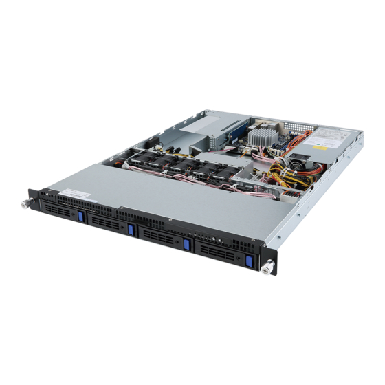
System Components/ 系统组件
4
2
1
1
1
3
No
1
2
3
4
5
6
7
CAUTION!
8
Before you remove or install the system
9
cover:
10
Make sure the system is not turned on
or connected to AC power.
注意!
CAUTION!
在卸下或安装系统机盖之前,请注意
To connect system fan connector, follow the instruction:
Blue/Red cable connect to odd numbered connector.
下列事项:
White/Amber cable connect to even numbered connector.
确保系统未开启且未连接到交流电源。
注意!
蓝/红电缆连连接于单数风扇插座。
白/橘电缆连连接于双数风扇插座。
Hard Disk Drive and Back Plane Board/ 硬盘驱动器与硬盘驱动器底板
6
7
8
5
4
No
Description
1
HDD#3
3
2
HDD#2
3
HDD#1
2
4
HDD#0
5
SGPIO header
6
Fan connector#13
7
Fan connector#14
8
Fan connector#11
1
4
9
Fan connector#12
4
10
ODD power connector
11
Fan connector#9
CAUTION!
Read the following guidelines before you begin to install the Hard disk drive:
Take note of the drive tray orientation before sliding it out.
The tray will not fit back into the bay if inserted incorrectly.
Make sure that the HDD is connected to the HDD connector on the backplane.
PCI Express Card/PCI Express 扩展卡
2
1
3
8
7
6
CAUTION!
Before you remove or install the PCI express card:
Make sure the system is not turned on or connected to AC power.
注意!
在安装扩展卡前,请注意下列事项:
确保系统未开启且未连接到交流电源。
Release
Lock out
PN:25ME0-G15000-CLS
Release and detach the inner member from the slide
1
G150-B10 Quick Installation Guide/G150-B10 快速安装说明
No.
Code
Description
1
CPU
Intel Xeon® processor D-1541, FCBGA1667 SoC (MB10-DS3)
2
SFP+1_2
SFP+ connectors #1/#2
3
LAN1_2
LAN ports
10
4
USB3_MLAN
BMC Management LAN port (top) / USB 3.0 ports (bottom)
5
CPU0_FAN
CPU fan connector
6
VGA
VGA port
7
SW_ID
ID switch button w/LED
8
SW_PWR
Power button w/LED
9
LED_STA
System Status LED
10
P12V_AUX1
8 pin power connector
11
FP_1
Front panel header
13
12
ATX1
24 pin main power connector
11
13
DIMM_P0_A0
Channel 1 slot 0
14
DIMM_P0_A1
Channel 2 slot 1
15
DIMM_P0_B0
Channel 3 slot 0
16
DIMM_P0_B1
Channel 4 slot 1
17
BAT1
Battery
18
PMBUS
PMBus connector
19
SATA_DOM0
SATA DOM power cable connector
12
20
SATA0
SATA 3 6Gb/s connector
21
SATA1
SATA 3 6Gb/s connector
22
SATA_2_3
SATA 3 6Gb/s connectors
23
SATA_4_5
SATA 3 6Gb/s connectors
24
SATA_SGPIO
SATA SGPIO header
25
COM1
Serial port cable connector
26
LED_BMC1
BMC firmware readiness LED
27
BP_1
HDD back plane board header
28
NVME_PH
NVME connector
29
TPM
TPM module connector
30
IPMB
IPMB connector
9
7
8
2
10
3
4
5
6
1
Description
HDD bays
System fan #9/#10 (FAN9/FAN10)
System fan #7/#8 (FAN7/FAN8)
System fan #5/#6 (FAN5/FAN6)
System fan #3/#4 (FAN3/FAN4)
System fan #1/#2 (FAN1/FAN2)
CPU and CPU heat sink
Memory slots
PCIe riser bracket
Power supply cage
HDD Backplane Board Components
9
11
12
13
14
15
16
17
18
19
20
21
22
10
3
2
1
No
Description
12
Fan connector#10
13
Fan connector#7
14
Fan connector#8
15
Fan connector#5
16
Fan connector#6
17
Fan connector#3
18
Fan connector#4
19
Fan connector#1
20
Fan connector#2
21
Fan connector#15
22
Fan connector#16
注意!
在滑出驱动器托盘之前,注意其方向。
托盘插入不当时,无法进入托槽。
确保硬盘驱动器连接到底板上的硬盘驱动
器底板。
5
No.
Name
1
Power Button and LED
4
2
ID Button
3
System Status LED
HDD Status LED
4
5/6
LAN1/2 Active/Link LEDs
Reset Button
7
NMI Button
8
Click
A ach the unit to the inner member
2
Motherboard Components/ 主板组件
No.
Code
31
CLR_CMOS
32
PCIE_1
33
ME_UPDATE
34
ME_RCVR
35
S3_MASK
Fan Duct/ 风扇散热片
1
2
System Fan/ 系统风扇
CAUTION!
Before you remove or install the system fan:
Make sure the system is not turned on or
connected to the AC power.
Disconnect all necessary cable connections.
Failure to observe these
2
warnings could result in personal injury or
damage to the equipment.
1
注意!
确保系统未开机且未连接到交流电源。
断开所有必要的线缆连接。若不遵循这些
警告,可能造成人员伤害或设备损坏。
System Front View
1
2
3
No
Description
1
ID button w/LED
2
Power button w/LED
3
HDD bays
Front Panel LED and Buttons/ 前面板 LED 说明
Description
Color
Status
Green
Solid On
System is powered on.
Green
Blink
System is in ACPI S1 state (sleep mode).
System is not powered on or in ACPI S5 state (power off).
N/A
Off
System is in ACPI S4 state (hibernate mode).
Press the button to activate system identifcation.
Solid On
System is operating normally.
Green
Degrade condition, may indicates:
Off
CPU failure
状态
DIMM killed
Critical condition, may indicates:
Power module failure
Solid On
System fan failure
Power supply voltage issue
System temperature
Amber
Non-critical condition, may indicates:
Redundant power module failure
Blink
Temperature and voltage issue
Chassis intrusion
System is not ready, may indicates:
POST error
N/A
N/A
NMI error
Processor or terminator missing
Green
On
HDD locate
Blink
HDD access
Amber
On
HDD access
Green/Amber
Blink
HDD fault
N/A
Off
No HDD access or no HDD fault.
Green
Solid On
Link between system and network or no access.
Green
Blink
Data transmission or receiving is occurring.
N/A
Off
No data transmission or receiving is occurring.
Press the button to reset the system.
Press the button to generate an NMI.
Rail Kit/ 导轨
M6-NUT
M6X13
M4X6
Fix the outer member/bracket assembly to the frame
3
Description
Clear CMOS jumper
1-2 Close: Normal operation (Default setting)
2-3 Close: Clear CMOS data.
PCI Express x16 slot
ME update jumper
1-2 Close: Normal operation (Default setting)
2-3 Close: ME update mode.
ME recovry jumper
1-2 Close: Normal operation. (Default setting)
2-3 Close: ME recovery mode.
S3 Power On Select jumper
1-2 Close: Stop an initial power on when BMC is not ready.
2-3 Close: Keep initial power on. (Default setting)
Memory Population Configuration/ 安装内存
Ranks PerDIMM
Type
and
Data Width
SRx4 ECC
RDIMM
RDIMM
SRx8 ECC
RDIMM
DRx8 ECC
RDIMM
DRx4 ECC
Note: DDR4 2400MHz is only available on Intel Xeon® D-1541 processor.
When only one DIMM is used, it must be populated in memory slot0 first.
System will not boot normally with incorrect populated sequence.
仅Intel Xeon® D-1541处理器支持DDR4-MHz内存。
只使用一个DIMM时,必须安装到内存插槽0。
若安装顺序有误,系统将不能正常引导。
1
3
2
Front & Rear/ 系统前部与后部概览
System Rear View
4
5 6
7 8 9
10
1
2
3
No
Description
1
Power supply fan
2
Power supply module cord socket
3
System Status LED
4
Power button w/LED
5
ID switch button w/LED
6
VGA port
7
USB 3.0 ports
8
10/100/1000 Server management LAN port
9
GbE LAN ports
10
SFP+ LAN ports
Power button/LED:
State
Green On
Off
8
7
6
5
4
3
2
1
编号
名称
颜色
1
电源按钮和LED
绿色
绿色
无亮灯
2
ID按钮
3
系统状态LED
绿色
橙色
无亮灯
硬盘驱动器LED
6
绿色
橙色
绿色/橙色
无亮灯
5/6
LAN1/LAN2活动LED
绿色
绿色
无亮灯
7
复位按钮
8
复位按钮
Bracket
Front Panel Header/ 前面板接头
No.
Pin Define
No.
Pin Define
24 23
1
Power LED+
2
5V Standby
4
ID LED+
3
No Pin
6
ID LED-
5
Power LED-
8
System Front Board LED+
7
HDD LED+
10
System Status LED-
9
HDD LED-
12
LAN1 Active LED+
11
Power Button
13
GND
14
LAN1 Link LED-
16
SMBus Data
15
Reset Button+
18
SMBus Clock
17
GND
2
1
20
Case Open
19
ID Switch+
22
LAN2 Active LED
21
ID Switch-
24
LAN2 Link LED-
23
NMI Switch-
HDD Back Plane Board Header/
硬盘驱动器底板接头
No.
Pin Define
No.
Pin Define
1 2
1
BP_SGP_CLK
2
No Connect
4
FAN_SGP_Gate
3
BP_SGP_GLD
6
GND
5
BP_SGP_DOUT
8
Reset
7
Key Pin
9
GND
10
BP_LED_A_N
12
GND
11
BP_LED_G_N
14
No Connect
13
BP_SGP_DIN
16
SMB_BP_DATA
15
GND
18
SMB_BP_CLK
17
GND
20
BMC_ACK
19
P_3V3_AUX
25 26
22
BMC_REQ
21
P_3V3_AUX
24
Key Pin
23
GND
26
GND
25
BP_PRESENSE
Speed (MT/s);
Slot Per Channel (SPC) and DIMM Per Channel (DPC)
1 Slot Per Channel
2 Slot Per Channel
1DPC
1DPC
2DPC
1600, 1866, 2133, 2400*
1600, 1866, 2133, 2400*
1600, 1866, 2133, 2400*
1600, 1866, 2133, 2400*
1600, 1866, 2133, 2400*
1600, 1866, 2133, 2400*
1600, 1866, 2133, 2400*
1600, 1866, 2133, 2400*
1600, 1866, 2133, 2400*
1600, 1866, 2133, 2400*
1600, 1866, 2133, 2400*
1600, 1866, 2133, 2400*
Power Supply/ 电源
CAUTION!
Before you remove or install the power
supplies:
Make sure the system is not turned on or
connected to AC power.
注意!
在替换或安装电源前,请注意下列事项:
确保系统未开启且未连接到交流电源
。
Speed LED Link/Activity
10/100/1000 LAN LED:
LED
State
Description
Yellow On
1Gbps data rate
Green On
100Mbps data rate
Off
10Mbps data rate
Speed LED
Link/Activity
LED
SFP+ LAN LED:
State
Description
Yellow On
1Gbps data rate
10 Gbps data rate
Green On
ID button/LED:
Description
State
Description
Blue On
System identifcation is active.
System is powered on
Off
System identifcation is disabled.
System is powered off
状态
说明
恒亮
系统处于开机状态。
闪烁
系统处于ACPI
S1状态(睡眠模式)。
系统未开机或处于ACPIS5状态(关机状态)。
不亮
系统处于ACPI S4状态(休眠模式)。
按下按钮启动系统识别功能。
恒亮
系统正常运行。
效能降低情形,可能为下列状况:
处理器问题
不亮
内存问题
严重情形,可能为下列状况:
电源模块故障
恒亮
系统风扇故障
电源电压问题
系统温度/电压问题
非严重情形,可能为下列状况:
冗余电源模块故障
闪烁
系统温度/电压问题
机箱侵入
系统未正常运行,可能为下列状况:
POST错误
不亮
NMI错误
处理器或终结器缺失
硬盘驱动器定位
亮
闪烁
硬盘驱动器访问
亮
硬盘驱动器访问
闪烁
硬盘故障
不亮
无硬盘驱动器访问
恒亮
系统和网络之间的链接
闪烁
网络访问
不亮
断开连接/待机
按此按钮启动系统。
按此按钮启动不可遮罩中断功能。
Release
lock in
Insert the unit to complete the installa on
4
Advertisement

Related Manuals for Gigabyte G150-B10


Summary of Contents for Gigabyte G150-B10
- Page 1 G150-B10 Quick Installation Guide/G150-B10 快速安装说明 Motherboard Components/ 主板组件 7 8 9 Front Panel Header/ 前面板接头 Code Description Code Description Intel Xeon® processor D-1541, FCBGA1667 SoC (MB10-DS3) CLR_CMOS Clear CMOS jumper Pin Define Pin Define SFP+1_2 SFP+ connectors #1/#2 1-2 Close: Normal operation (Default setting)
- Page 2 GIGABYTE products have not intended to add and safe from hazardous substances (Cd, Pb, Hg, Cr+6, PBDE and PBB). The parts and components have been carefully selected to meet RoHS requirement.