Table of Contents
Advertisement
Quick Links
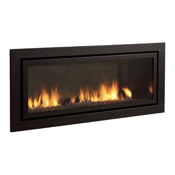
Regency Gem54
Gas Fireplace
www.regency-fire.com.au
WARNING:
If the information in these instructions are not followed
exactly, a fire or explosion may result causing property
damage, personal injury or loss of life.
FOR YOUR SAFETY
Do not store or use gasoline or other flammable vapors and
liquids in the vicinity of this or any other appliance.
Installation and service must be performed by a qualified
installer, service agency or the gas supplier.
918-784f
Installer: Please complete the details on the back cover
and leave this manual with the homeowner.
Homeowner: Please keep these instructions for future reference.
Owners &
Installation Manual
MODELS: GEM54NG1-R
GEM54LPG1-R
LISTINGS AND CODE APPROVALS
These gas appliances have been tested in
accordance with AS4558 / NZS 5262 and
have been certified by the Australian Gas
Association for installation and operation
as described in these Installation and
Operating Instructions.
Your unit should be serviced annually
by an authorised service person.
FOR YOUR SAFETY
What to do if you smell gas:
Do not try to light any appliance
Do not touch any electrical switch:
do not use any phone in your
building.
Immediately call your gas supplier
from a neighbour's phone. Follow
the gas supplier's instructions.
If you cannot reach your gas
supplier, call the fire department.
GEM54ULPG1-R
12.19.16
Advertisement
Table of Contents

Related Manuals for Regency Gem54


Summary of Contents for Regency Gem54
- Page 1 Regency Gem54 Owners & Gas Fireplace Installation Manual MODELS: GEM54NG1-R GEM54LPG1-R GEM54ULPG1-R LISTINGS AND CODE APPROVALS These gas appliances have been tested in accordance with AS4558 / NZS 5262 and have been certified by the Australian Gas Association for installation and operation as described in these Installation and Operating Instructions.
- Page 2 The model Gem54 has been approved by AGA for both safety and efficiency. As it also bears our own mark, it promises to provide you with economy, comfort and security for many trouble free years to follow.
-
Page 3: Table Of Contents
Venting Arrangements ..........21 Allowable Horizontal Terminations for Gem54-lpg/ ulpg ..............21 Main Assembly ............52 Venting Arrangements ..........24 Accessories ..............53 Allowable Vertical Terminations for Gem54-ng ..24 Venting Arrangements ..........25 Allowable Vertical Terminations for Gem54-lpg/ WARRANTY ULPG ..............25 Unit Installation with Horizontal Termination ....26 Unit Installation with Vertical Termination ....27... -
Page 4: Data Badge
SAFETY LABEL data badge This is a copy of the badge that accompanies each Gem54™-NG Direct Vent Gas Fireplace. We have printed a copy of the contents here for your review. NOTE: Regency units are constantly being improved. Check the badge on the unit and if there is a difference, the badge on the unit is the correct ®... -
Page 5: Dimensions
DIMENSIONS UNIT DIMENSIONS 52-5/8 (1337mm) 59 (1499mm) 19-3/4 (502mm) 10-5/8 (270mm) 1-1/2 20-1/2 (521mm) (38mm) 48-1/2 (1232mm) FACEPLATE & DOOR FRAME OVERLAY DIMENSIONS Gem 54 Regency Gas Fire... -
Page 6: Important Message
INSTRUCTIONS used in this appliance. NOT INTENDED FOR FIREPLACE 15) The appliance area must be kept clear and The Gem54™ Direct Vent Fireplace must be INSERT. free of combustible materials, (gases and installed in accordance with these instructions. other flammable vapours and liquids). -
Page 7: Installation Checklist
7) Test Gas Pressure (Refer to "Gas Pipe Pres- 3) The Gem54 Direct Vent Gas Fireplace can sure Testing" section). be installed in a recessed position or framed out into the room as in A, B, C and D. -
Page 8: Clearances
Front to Back Wall (Maximum) Note 0" No hearth required Installed Close to Ceiling Installed Close to Floor NON-COMBUSTIBLE REQUIREMENTS Metal Stud (header) 60-1/2" (1537mm) Wood Stud Wood Stud Non-combustible Material 52-5/8 Non-combustible Material 4" 5-11/16 (102mm) (144mm) Gem 54 Regency Gas Fire... -
Page 9: Non Combustible Facing Board
7) Paint walls using a high quality paint which will withstand the high temperatures being emitted from this appliance. Non-combustible board MUST BE PRIMED. Note: Incorrectly sealed joints may crack. Keep sealant thickness to a minimum. Gem 54 Regency Gas Fire... -
Page 10: Mantel Clearances
Top of 28-1/8 Fireplace (724mm) Opening To Floor MANTEL LEG CLEARANCES Combustible mantel leg clearances as per diagram: MANTEL LEG 4” (102mm) Non-Combustible 1.5" (38mm) 11-1/2” (292mm) Allowable mantel leg projection 14” (356mm) 15-3/4” (400mm) Gem 54 Regency Gas Fire... -
Page 11: Framing & Finishing
13mm 25mm faceplate. Factory Setting Nailing Strip 1 Forward 58-3/16 (1478mm) Unit 25mm 13mm Nailing Strip ½ Forward Unit 38mm 0mm (flush) Nailing Strip Flush w/unit Factory Set Unit Gem 54 Regency Gas Fire... - Page 12 The nailing strips can be adjusted back - up to 1” (25mm) to allow for varying thicknesses in non-combustible material & wall finishes. Metal Stud (Header) on edge Metal Stud (Header) on edge Non-Combustible Facing (Located on the right side of the fireplace) Gem 54 Regency Gas Fire...
-
Page 13: Unit Assembly Prior To Installation
VENTING INTRODUCTION The Gem54™ uses the "balanced flue" technology Co Axial system. The inner liner vents products of combustion to the outside while the outer liner draws outside combustion air into the combustion chamber thereby eliminating the need to use heated room air for combustion and losing warm room air up the chimney. -
Page 14: Vent Restrictor Position
3) Adjust the vent restrictor plate to the required vent restrictor position as per the diagrams shown. 4) Once the vent restrictor plate is in the required position, secure with screws. ent Restrictor Settings for Gem54-LP ent Restrictor Settings for Gem54-NG... -
Page 15: Exterior Flue Termination Locations
(IV) A flue terminal of this type shall not be located under a roofed area unless the roofed area is fully open on at least two sides and a free flow of air at the appliance is achieved. Gem 54 Regency Gas Fire... -
Page 16: Venting Arrangements
® These venting systems, in combination with the Gem54, have been tested and listed as a direct vent system by AGA. The location of the termination cap must conform to the requirements in the Vent Terminal Locations diagram from the "Exterior Vent Termination Locations" section. -
Page 17: Rigid Pipe Venting Systems
Do not combine venting components from When using Rigid Vent other than different venting systems. Simpson Dura-Vent, 3 screws must be used to secure rigid pipe to adaptor. Exception: However, use of the the AstroCap is acceptable with all systems. Gem 54 Regency Gas Fire... -
Page 18: 5" X 8" Rigid Pipe Cross Reference Chart
5” X 8” RIGID PIPE CROSS REFERENCE CHART Components from different Manufacturers may not be mixed. Not all rigid pipe components are available directly from Regency. Note: The listed manufacturers may have other lengths not shown on this chart, which would also be approved. - Page 19 1 foot of run towards the termination. 36” (914mm) 29-13/16” (757mm) 39-7/16” (1002mm) Never allow the vent to run downward - this could cause high temperatures and may present a possible fi re hazard. 48” (1219mm) 38-1/4” (972mm) 47-7/8” (1216mm) Gem 54 Regency Gas Fire...
-
Page 20: Venting Arrangements
Horizontal vent must be supported every 3 ft / 91 cm. • Firestops are required at each floor level and whenever passing through a wall. • A wall thimble is mandatory for all horizontal terminations due to high temperatures. Gem 54 Regency Gas Fire... -
Page 21: Venting Arrangements
VENTING ARRANGEMENTS ALLOWABLE HORIZONTAL TERMINATIONS FOR GEM54-LPG/ULPG The diagram shows all allowable combinations of vertical runs with horizontal terminations, using one 90 (two 45 elbows equal one 90 elbow). Note: Must use optional rigid pipe adapter (Part# 770-994) when using Rigid Pipe Venting Systems. - Page 22 1.2m Max. 3m Min. 2.1m Max. 1.8m Min. 1.8m Max. 3.3m Min 2.7m Max. Please note minimum .3m between 90 elbows is required. VENT RESTRICTOR SETTING: Vent restrictor factory set at Set 1, no adjustment required. Gem 54 Regency Gas Fire...
- Page 23 1.5m Min. 1.8m Max. 2.4m Min. horizontal. 1.8m Min. 2.4m Max. 2.7m Min. Please note minimum .3m between 90 elbows is required. VENT RESTRICTOR SETTING: Vent restrictor factory set at Set 1, no adjustment required. Gem 54 Regency Gas Fire...
-
Page 24: Venting Arrangements
VENTING ARRANGEMENTS ALLOWABLE VERTICAL TERMINATIONS FOR GEM54-NG The shaded area in the diagram shows all allowable Horizontal (Feet) combinations of straight vertical and offset to vertical terminations, using two 90 elbows, with Rigid Pipe Venting Systems for Natural Gas. Two 45 elbows equal to one 90 elbow. -
Page 25: Venting Arrangements
VENTING ARRANGEMENTS ALLOWABLE VERTICAL TERMINATIONS FOR GEM54-LPG/ULPG Horizontal (Feet) The shaded area in the diagram shows all allowable combinations of straight vertical and offset to vertical terminations, using two 90 elbows, with Rigid Pipe Venting Systems for Natural Gas. Two 45 elbows equal to one 90 elbow. -
Page 26: Unit Installation With Horizontal Termination
See "THIS UNIT MUST ALWAYS "Exterior Vent Termination Locations" section for more details. TERMINATE / VENT Diagram 4 DIRECTLY TO THE OUTDOORS." Gem 54 Regency Gas Fire... -
Page 27: Unit Installation With Vertical Termination
Diagram 5 or local codes. Note that for steep roof pitches, the vertical height must be increased. "THIS UNIT MUST ALWAYS TERMINATE / VENT DIRECTLY TO THE OUTDOORS." Diagram 3 Gem 54 Regency Gas Fire... -
Page 28: Unit Installation
NOTE: Horizontal sections must be sup- ported at intervals not exceeding 3 Wall Thimble* Screws feet (0.9 meter). (Flame picture and *Mandatory on all performance will be affected by sags horizontal terminations. in the liner). Gem 54 Regency Gas Fire... -
Page 29: High Elevation
NOTE: A shutoff / dante valve should be built into the gas control, and should be checked supplied in or near the unit (or as per local at the pressure test point. codes) for ease of servicing this appliance. Gem 54 Regency Gas Fire... -
Page 30: Conversion From Ng To Lpg
CONVERSION KIT #476-968 FROM NG TO ULPG Conversion Kit # 476-967 from NG to LP and Conversion Kit #476-968 from NG to ULPG FOR GEM54™ USING SIT 820 NOVA GAS VALVE for Gemfi re54 using SIT 820 NOVA Gas Valve... - Page 31 (see below). Burner Bracket 15) Reinstall new burner orifi ce LPG stamped #51 or ULPG burner orifi ce stamped # 52 and tighten. 04/23/09 918-798 Gem 54 Regency Gas Fire...
- Page 32 18) Check that the screw is clean and if necessary remove dirt. 19) Flip the screw (Fig. 3). Fig. 6 WARNING! Also check that the pilot and main burner injectors Fig.3 are appropriate for the gas type. Gem 54 Regency Gas Fire 04/23/09 918-798...
-
Page 33: Aeration Adjustment
Wiring errors can cause improper and dangerous operation. Ground Blue (Neutral) White HIGH Yellow/Green Brown 240 V AC (Live) Ground 50 HZ Black White Fan Thermodisc (Normally open) 909-185 Part #: 909-185 Gem 54 Regency Gas Fire... -
Page 34: Reflective Panel Installation
Left Side Bracket Fit side panel tab into slot Right side back panel tab fi tted into slot Left side panel in position Bracket shown in place on right side of the fi rebox 10/08/09 918-754a Gem 54 Regency Gas Fire... -
Page 35: Glass Crystals Or Optional Ceramic Stones
GLASS CRYSTALS OR OPTIONAL CERAMIC STONES INSTALLATION ON BURNER Gem54 Glass Crystal/Optional Ceramic Spa Stone Quantity Glass Crystals only 2 bags *Ceramic Spa Stones 1 bag glass crystals + 70 ceramic spa stones * 1 bag of glass crystals must be used on burner when using ceramic spa stones. -
Page 36: Log Set Installation
3) Pin clips are attached to the lip edge of the bottom cover (not the burner) see diagrams 3 & 4. Measurements to centre of pins. Burner Bottom Cover Side measurements Lip Edge from corner edge. Diagram 4 Diagram 3 19-3/16 19-3/16 Gem 54 Regency Gas Fire 7-3/4 4-3/4 15-3/4... - Page 37 4) Install the glass crystals (see glass crystal installation section in this manual). Diagram 6 5) Place platinum embers on glass crystals as shown in diagram 7. Diagram 7 6) If installing optional pebbles - install pebbles before log installation. Diagram 8 Gem 54 Regency Gas Fire...
- Page 38 Note: Logs should be oriented exactly as shown in diagram 10. Diagram 10 9) Install the following: a) *Glass door b) *Faceplate and door frame *Refer to these sections in the HZ54 manual for detailed instructions. Log Set Installed (shown with optional pebbles) Diagram 11 Gem 54 Regency Gas Fire...
-
Page 39: Screen & Door Frame Overlay Installation
6) Place 2 of the supplied magnets on the lower corners of the Door install door frame with screen onto unit. Frame Overlay, this will keep the Faceplate in position after it has been installed. Magnet Position Gem 54 Regency Gas Fire 12/15/11 918-827a... -
Page 40: Faceplate Installation
There is a top and bottom, the top fascia is all one piece - the bottom fascia is a single piece to be First Mounting Slot installed once the top fascia is in place. (recommended) Gem 54 Regency Gas Fire 918-827a 12/15/11... - Page 41 3b) Ensure the bottom fascia is lined up and fl ush with the top fascia. Faceplate Mounting Slots 3) Line up the bottom fascia with the top fascia. Completed Faceplate & Door Frame Overlay Installation Faceplate Screen Door Frame 12/15/11 918-827a Gem 54 Regency Gas Fire...
-
Page 42: Operating Instructions
Use a non-abrasive cleaner and DO NOT ATTEMPT TO CLEAN THE GLASS WHILE IT IS HOT. Gem 54 Regency Gas Fire... -
Page 43: Copy Of Lighting Plate Instructions
COPY OF LIGHTING PLATE INSTRUCTIONS Gem 54 Regency Gas Fire... -
Page 44: Fan Service
3) Remove the glass door. b) Remove the 3 screws shown below at the bottom of the glass door c) Swing the door out 45 from the bottom and lift up and out. Fan Access Panel Gem 54 Regency Gas Fire... - Page 45 12) Remove from unit, bracket and attached 6" section of 3" duct from elbow at left side and set aside. 13) Remove ground wire. 14) Near the switch box, cut cable tie and slide the heat sleeve to expose spade connectors Cable Tie Gem 54 Regency Gas Fire...
-
Page 46: Wiring
Star washer Blue Molex Connector #8 Ground Lug (Neutral) White (mobile home approved) HIGH Yellow/Green Brown 240 V AC (Live) Ground 50 HZ Black White Power Fan ground Fan Thermodisc cord (Normally open) ground wire Gem 54 Regency Gas Fire... -
Page 47: Maintenance Instructions
4) Drop the thermocouple or thermopile down should be done by a licensed or through the extrusion and pull it out of the qualified service person. 8) Verify operation after servicing. unit. 5) Reinstall the new ones in reverse order. Gem 54 Regency Gas Fire... -
Page 48: Glass Door Removal
3) Remove the faceplate by lifting it up off the hinges on the sides of the firebox. 4) Remove the door frame overlay by swinging out 45 from the bottom and lift up and out. Gem 54 Regency Gas Fire... -
Page 49: Dc Spark Box Battery Replacement
4) Remove the battery cover from the DC Spark Box. 5) Remove the AA battery and replace with a DC Spark Box Bracket Assembly new one. removed from firebox. 6) Reverse steps 4 to 1. Gem 54 Regency Gas Fire... -
Page 50: Valve Tray Replacement
4) Remove the door frame overlay by swinging out 45 from the bottom and lift up and out. Aerial View of the inside of the unit shown. Gem 54 Regency Gas Fire... - Page 51 8) Disconnect the ON/OFF connector wires from the valve. ON/OFF Connector Wires 9) Disconnect the DC Sparker leads at the valve. 12) Slightly lift out valve tray. 13) Disconnect the inlet gas line. DC Sparker Lead 14) Replace valve and reverse steps. Gem 54 Regency Gas Fire...
-
Page 52: Parts List
Fan 240V Assembly 904-645 Orifice # 51 910-142 Fan Thermodisc 910-096 Pilot Hood 3 way 918-784 Manual 910-036 Pilot Orifice - NG 910-037 Pilot Orifice - LP 910-341 Thermopile 910-386 Thermocouple 910-007 Electrode 910-432 Pilot Tube Gem 54 Regency Gas Fire... -
Page 53: Accessories
31) 476-944 Faceplate & Door Frame Overlay - Black 476-947 Faceplate & Door Frame Overlay - Stainless Steel 946-671 Cobalt Blue Glass Crystals 946-672 Natural River Pebbles 476-540 Door frame w/ Glass 32) 476-532 Screen Assembly Gem 54 Regency Gas Fire... -
Page 54: Warranty
FPI Fireplace Products International Ltd. (“the manufacturer”) through its wholly owned subsidiary, Fireplace Products Australia Pty Ltd (for Australia and New Zealand customers) and sold under the Regency® brand of fireplace products (collectively referred to herein as “FPI”), extends this Limited Lifetime Warranty to the original purchaser of this appliance provided the product remains in the original place of installation. - Page 55 Limited Lifetime Warranty. Revision Date: December 2016 Regency Gas Products Warranty Gem 54 Regency Gas Fire...
- Page 56 FPI may void this warranty. INCORRECT INSTALLATION OR GAS PRESSURE SETTINGS ARE NOT COVERED BY WARRANTY. A SERVICE OR CALLOUT FEE WILL BE CHARGED IN THESE CIRCUMSTANCES. Revision Date: December 2016 Regency Gas Products Warranty Gem 54 Regency Gas Fire...
- Page 57 (b) Loss means any expense, cost or damage of any kind and includes Consequential Loss and a fine or penalty imposed by a statutory or other authority. Revision Date: December 2016 Regency Gas Products Warranty Gem 54 Regency Gas Fire...
- Page 58 Product Registration and Customer Support: Thank you for choosing a Regency Fireplace. Regency strives to be a world leader in the design, manufacture, and marketing of hearth products. To provide the best support for your product, we request that you complete a product registration form at http://www.regency-fire.com.au/Customer-Care/Warranty-Registration.aspx...
- Page 59 Product Registration and Customer Support: Thank you for choosing a Regency Fireplace. Regency strives to be a world leader in the design, manufacture, and marketing of hearth products. To provide the best support for your product, we request that you complete a product registration form found on our Web Site under Customer Care within ninety (90) days of purchase.
- Page 60 Gem 54 Regency Gas Fire...
- Page 61 NOTES notes Gem 54 Regency Gas Fire...
- Page 62 NOTES Gem 54 Regency Gas Fire...
- Page 63 Gem 54 Regency Gas Fire...
- Page 64 Dealer Name & Address: ______________________________________________ ___________________________________________________________________ Installer: ___________________________________________________________ Phone #: ___________________________________________________________ Date Installed: ______________________________________________________ Serial No.: __________________________________________________________ Regency and Gemfire are trademarks of FPI Fireplace Products International Ltd. © Copyright 2016, FPI Fireplace Products International Ltd. All rights reserved. Printed in Canada...