
Related Manuals for Toro Pro Force Debris


Summary of Contents for Toro Pro Force Debris
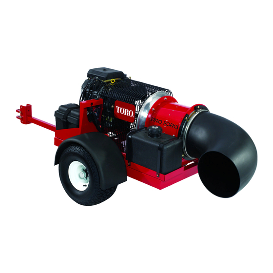
- Page 1 Form No. 3443-292 Rev A Pro Force ® Debris Blower Model No. 44552—Serial No. 408000000 and Up Model No. 44552TE—Serial No. 408000000 and Up *3443-292* Register at www.Toro.com. Original Instructions (EN)
- Page 2 RF2CAN: Mexico Electromagnetic Compatibility Certification Handheld: RF2CAN: Korea Electromagnetic Compatibility Certification (Decal provided in separate kit) Handheld: RF2CAN: © 2020—The Toro® Company Contact us at www.Toro.com. 8111 Lyndale Avenue South Printed in the USA Bloomington, MN 55420 All Rights Reserved...
-
Page 3: Figure 1
Whenever you need service, genuine Toro parts, or accessories contain lead and lead additional information, contact an Authorized Service Dealer or Toro Customer Service and have the model compounds, chemicals known to and serial numbers of your product ready. Figure 1... -
Page 4: Table Of Contents
Adjusting the Blower Nozzle Direction....19 Moving the Machine from the Job Model No. Site..............19 The Nozzle-Position Gauge......20 Serial No. Operating the Optional Lights ......20 Operating Tips ..........21 After Operation ............ 21 This manual identifies potential hazards and has After Operation Safety ........ -
Page 5: Safety
Safety Storage Safety..........42 Storing the Machine.......... 42 This machine has been designed in accordance with ANSI B71.4-2017. General Safety This product is capable of throwing objects. Always follow all safety instructions to avoid serious personal injury. • Read and understand the contents of both this Operator’s Manual and the operator’s manual of the traction unit before using this machine. -
Page 6: Safety And Instructional Decals
Safety and Instructional Decals Safety decals and instructions are easily visible to the operator and are located near any area of potential danger. Replace any decal that is damaged or missing. decal115-5106 115-5106 decal131-6766 131-6766 1. Warning—read the Operator's Manual. 1. - Page 7 decal140-6767 140-6767 1. Warning—read the Operator’s Manual. 4. Thrown object hazard—keep bystanders away. 2. Warning—all operators should be trained before operating 5. Warning—stay away from moving parts; keep all guards and the machine. shields in place. 3. Warning—do not start the engine when the machine is 6.
-
Page 8: Setup
Determine the left and right sides of the machine from the normal operating position. Connecting the Battery Parts needed for this procedure: — Grafo 112X grease (Toro Part No. 505-47) Procedure Remove the 2 hairpins that secure the battery cover to the battery box, and remove the cover... -
Page 9: Mounting The Hitch To The Debris Blower
T-bolt and nut. Coat the battery terminals with Grafo 112X (skin over) grease (Toro Part No. 505-47). Slide the positive battery-cable insulator over the positive battery terminal. Assemble the battery cover to the battery box,... -
Page 10: Installing The Batteries Into The Handheld Remote
Installing the Batteries into the Handheld Remote Parts needed for this procedure: g341668 Figure 5 Handheld remote 1. Bolt 3. Hitch tube AAA batteries 2. Hitch clevis 4. Locknut Procedure Raise or lower the hitch clevis to align it level Remove the 6 screws securing the cover halves with the hitch of the tow vehicle. -
Page 11: Product Overview
Product Overview battery compartment. If you install the batteries improperly, you will not damage the machine, but the handheld remote will not operate. Controls Handheld Remote LED Light The LED light indicates communication between the handheld remote communication and the wireless-control module (Figure g341771... - Page 12 • Press button (turtle icon) DECREASE ENGINE SPEED the to decrease the speed of the engine. • Pressing the INCREASE ENGINE SPEED buttons at the same time DECREASE ENGINE SPEED returns the engine to idle. Throttle Lever Use the throttle lever to adjust the speed of the engine (Figure 10).
-
Page 13: Specifications
Contact • Do not modify this equipment in any manner. your Authorized Service Dealer or authorized Toro distributor or go to www.Toro.com for a list of all approved attachments and accessories. Fuel Safety To ensure optimum performance and continued safety •... -
Page 14: Fuel Specification
Fuel Specification Note: The fuel tank cap contains a gauge which shows the fuel level. Important: Using unapproved fuel may cause performance problems and/or engine damage which may not be covered under warranty. Type Minimum octane rating 87 (US) or 91 (research octane;... -
Page 15: During Operation
During Operation accessories that may be required by law, such as lights, turn signals, slow-moving vehicle (SMV) signs, and others as required. During Operation Safety • If the machine ever vibrates abnormally, stop the machine immediately, shut off the engine, remove the key, wait for all moving parts to stop, and General Safety inspect for damage. -
Page 16: Diagnostic Light
Diagnostic Light • The handheld remote has low battery power. • The wireless-control module is not associated with The diagnostic light (Figure 14) indicates the status of a handheld remote. the electronic system and the communication status with the handheld remote. Active Fault Flash Code The active fault flash code runs when the TEC controller detects an active fault. -
Page 17: Shutting Off The Engine
Rotate the ignition switch to the S position. more than 2.5 hours without communication from TART the handheld remote. The power-save mode is a Important: Do not hold the ignition key in low-current state of the wireless-control module. In the start position for more than 10 seconds the power-save mode, the wireless-control module at a time. - Page 18 g341942 g343718 Figure 17 Figure 18 1. Choke lever 2. Throttle lever 1. R 3. R OTATE NOZZLE LEFT OTATE NOZZLE RIGHT button button 2. E button 4. I Rotate the engine ignition key to the NGINE START NCREASE ENGINE SPEED button position.
-
Page 19: Adjusting The Blower Nozzle Direction
g343720 g343719 Figure 19 Figure 20 1. D 3. I 1. D 2. E button ECREASE ENGINE SPEED NCREASE ENGINE SPEED ECREASE ENGINE SPEED NGINE STOP button button button 2. E button NGINE START Press the button (Figure 20). ENGINE STOP If the choke lever is in the O position, move the... -
Page 20: The Nozzle-Position Gauge
The Nozzle-Position Gauge • When the pointer is in the same colored region on the decal, that indicates that the chute opening is positioned more parallel to the ground. The nozzle-position gauge (Figure 22) is located behind the turbine housing, above the fuel tank. •... -
Page 21: Operating Tips
Operating Tips • Do not tow the machine faster than 88 km/h (55 mph). Recommended off-road towing is not to • Practice operating the blower. Blow the same exceed 24 km/h (15 mph). direction that the wind blows to prevent material •... -
Page 22: Maintenance
Determine the left and right sides of the machine from the normal operating position. Note: Download a free copy of the electrical or hydraulic schematic by visiting www.Toro.com and searching for your machine from the Manuals link on the home page. -
Page 23: Recommended Maintenance Schedule(S)
Recommended Maintenance Schedule(s) Maintenance Service Maintenance Procedure Interval • Check the condition and the tension of the belt. After the first 8 hours • Check the torque of the wheel lug nuts. After the first 10 hours • Check the engine oil level. •... -
Page 24: Daily Maintenance Checklist
Daily Maintenance Checklist Duplicate this page for routine use. Maintenance Check Item For the week of: Mon. Tues. Wed. Thurs. Fri. Sat. Sun. Check the engine oil level. Clean the engine screen and the oil cooler. Inspect the air filter pre-cleaner. -
Page 25: Pre-Maintenance Procedures
Pre-Maintenance Engine Maintenance Procedures Engine Safety • Shut off the engine before checking the oil or CAUTION adding oil to the crankcase. Failure to properly maintain the machine • Do not change the governor speed or overspeed could result in premature failure of machine the engine. - Page 26 Installing the Air Filter Note: To reduce the amount of dust dislodged, avoid knocking the filter against the air-filter Important: To prevent engine damage, always housing. operate the engine with the complete air-cleaner Inspect the air-filter element. assembly installed. Note: Check the sealing end of the filter.
-
Page 27: Engine Oil Specification
Engine Oil Specification Oil Type: Detergent oil (API service SJ or higher) Oil Viscosity: Refer to the table below that follows: g341990 g341978 Figure 29 Figure 27 1. Oil-fill cap (valve cover) Remove the dipstick and wipe the end clean Checking the Engine-Oil (Figure 28). -
Page 28: Changing The Oil
Changing the Oil Service Interval: Every 100 hours Change the oil more frequently when the operating in dusty or sandy conditions. Crankcase capacity: 2 L (67 oz)—with the filter Start the engine and let it run 5 minutes. Note: Warm oil drains better. Park the machine so that the drain side is slightly lower than the opposite side to ensure the oil drains completely. -
Page 29: Servicing The Spark Plugs
Apply a thin coat of new oil to the rubber gasket on the replacement filter (Figure 33). Install the replacement oil filter to the filter adapter, turn the oil filter clockwise until the rubber gasket contacts the filter adapter, then tighten the filter an additional 2/3 to 1 turn (Figure 34). -
Page 30: Cleaning The Engine Screen And The Oil Cooler
Fuel System Note: if the air gap is not correct, bend the side electrode to adjust the air gap. Maintenance Thread the spark plug into the engine, and torque the plug to 27 N∙m (20 ft-lb). Repeat steps through at the other cylinder. Servicing the Carbon Canister Cleaning the Engine Screen... -
Page 31: Replacing The Fuel Filter
Move the spring-type hose clamps on both sides of the carbon canister purge-line filter away from the filter (Figure 39). g342101 Figure 40 1. Fuel filter 3. Fuel hose 2. Hose clamp Remove the filter from the fuel lines. g018506 Install a new filter and move the hose clamps Figure 39 close to the filter... -
Page 32: Electrical System Maintenance
Electrical System Install the fuel line onto the fuel filter. Slide the hose clamp close to the fuel filter to secure the Maintenance fuel line (Figure 40). Important: Before welding on the machine, disconnect the controller and the negative cable from the battery to prevent damage to the electrical system. -
Page 33: Drive System Maintenance
Replacing the Machine Fuses Drive System At the front, inboard side of the control tower, Maintenance remove the fuse-block cover from the fuse block (Figure 42). Checking Tire Air Pressure Service Interval: Before each use or daily Check the tire pressure (Figure 44). -
Page 34: Belt Maintenance
Belt Maintenance Figure 45 is an example of tire wear caused by under inflation. Adjusting the Nozzle-Control Belt Tension Service Interval: After the first 8 hours Every 50 hours If the nozzle-control belt slips while changing blower-nozzle direction, adjust the belt tension. g010294 Prepare the machine for maintenance;... -
Page 35: Blower Maintenance
Blower Maintenance While holding belt tension, tighten the 2 flange capscrews and 2 flange locknuts. Checking the Blower-Nozzle Clamp Service Interval: Before each use or daily Prepare the machine for maintenance; refer to Preparing for Machine (page 25). Check the blower-nozzle clamp for signs of wear or damage (Figure 48). -
Page 36: Handheld Remote Maintenance
Handheld Remote Maintenance Handheld Remote and the Wireless-Control Module The handheld remote must link with the wireless-control module before you can use the remote control system. The handheld remote is associated to the wireless-control module at the factory. When you need to re-establish handheld remote and wireless-control module communication g017855 (e.g., introducing a new or spare remote control to an... -
Page 37: Replacing The Remote Batteries
Release the button (Figure ROTATE NOZZLE LEFT 51), and rotate the ignition key to the S position. Note: The remote-control system is ready for use with the associated handheld remote. Replacing the Remote Batteries Battery specification: AAA (1.5 V) Quantity: 4 Remove the 6 screws securing the cover halves g343880 Figure 50... - Page 38 onto the battery compartment to avoid damaging the terminal cradles. You will not damage the machine if you incorrectly installing the batteries in the handheld remote, but the handheld remote will not operate. g341771 g341769 Figure 53 1. Positive battery polarity Ensure that the steel gasket and rubber seal are seated in the channel in the cover half and align the back cover to the front cover...
-
Page 39: Troubleshooting Fault Codes
The wire harness is damaged; contact your authorized Toro distributor. The wireless-control module is damaged; contact your authorized Toro Distributor. Flash once—pause—flash 2 The software version in Associate the handheld remote;... -
Page 40: Entering Diagnostic Mode And Checking The Codes
Entering Diagnostic Mode and Checking the Codes Turn the ignition key to the S position. Remove the tethered cap from the single-pin connector and the single-socket connector (Figure 54A). Plug the single-pin connector into the single-socket connector (Figure 54B). g342081 Figure 55 Plug the single-pin connector into the single-socket connector... -
Page 41: Cleaning
Cleaning Washing the Machine Important: Do not use brackish or reclaimed water to clean the machine. Important: Do not pressure wash the machine. • Wash the machine with mild detergent and water. • Avoid excessive use of water, especially near the control console. -
Page 42: Storage
Paint all scratched or bare metal surfaces. Paint spark plug wire. is available from your authorized Toro distributor. Remove grass clippings, dirt, and grime from the Store the machine in a clean, dry garage or external parts of the entire machine, especially storage area. - Page 43 Notes:...
- Page 44 Notes:...
- Page 45 Notes:...
- Page 46 The Toro Company (“Toro”) respects your privacy. When you purchase our products, we may collect certain personal information about you, either directly from you or through your local Toro company or dealer. Toro uses this information to fulfil contractual obligations - such as to register your warranty, process your warranty claim or to contact you in the event of a product recall - and for legitimate business purposes - such as to gauge customer satisfaction, improve our products or provide you with product information which may be of interest.
- Page 47 While the exposure from Toro products may be negligible or well within the “no significant risk” range, out of an abundance of caution, Toro has elected to provide the Prop 65 warnings. Moreover, if Toro does not provide these warnings, it could be sued by the State of California or by private parties seeking to enforce Prop 65 and subject to substantial penalties.
- Page 48 Countries Other than the United States or Canada Customers who have purchased Toro products exported from the United States or Canada should contact their Toro Distributor (Dealer) to obtain guarantee policies for your country, province, or state. If for any reason you are dissatisfied with your Distributor's service or have difficulty obtaining guarantee information, contact your Authorized Toro Service Center.