Table of Contents
Advertisement
Quick Links
Advertisement
Table of Contents

Related Manuals for SRAM Rockshox Reverb AXS XPLR 2022


Summary of Contents for SRAM Rockshox Reverb AXS XPLR 2022
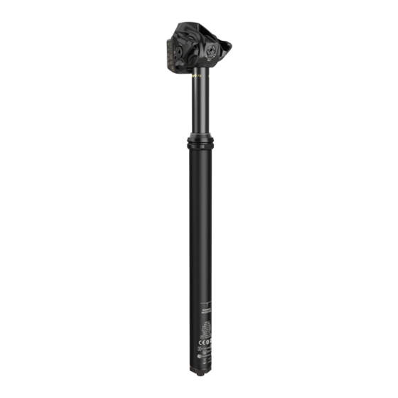
- Page 1 2022 Reverb AXS XPLR SERVICE MANUAL GEN.0000000006421 Rev A © 2021 SRAM, LLC...
- Page 2 LAW. FOR A FULL UNDERSTANDING OF YOUR RIGHTS, CONSULT THE LAWS OF YOUR COUNTRY, PROVINCE, OR STATE. EXTENT OF LIMITED WARRANTY Except as otherwise set forth herein, SRAM warrants its bicycle components to be free from defects in materials or workmanship for a period of two (2) years after original purchase of the product.
- Page 3 SAFETY FIRST! We care about YOU. Please, always wear your safety glasses and protective gloves when servicing RockShox products. Protect yourself! Wear your safety gear!
-
Page 4: Table Of Contents
TABLE OF CONTENTS ROCKSHOX SERVICE ......................................5 PART PREPARATION ..............................................5 SERVICE PROCEDURES ..............................................5 PARTS, TOOLS, AND SUPPLIES ..........................................6 RECOMMENDED SERVICE INTERVALS ........................................7 TORQUE VALUES ................................................7 EXPLODED VIEW - SEATPOST ..................................8 SEATPOST SERVICE ......................................9 50 HOUR SERVICE COLLAR/WIPER SEAL LUBRICATION ........................................9 200/600 HOUR SERVICE SEATPOST REMOVAL .............................................. -
Page 5: Rockshox Service
Information contained in this publication is subject to change at any time without prior notice. Your product's appearance may differ from the pictures contained in this publication. For recycling and environmental compliance information, please visit: www.sram.com/en/company/about/environmental-policy-and-recycling. P a r t P r e p a r a t i o n Remove the component from the bicycle before service. -
Page 6: Parts, Tools, And Supplies
• Maxima PLUSH Dynamic Suspension Lube • Torque wrench • RockShox Suspension Cleaner or isopropyl alcohol • TORX bit socket: T25 • SRAM Butter Grease • TORX wrench: T25 RockShox Tools • RockShox shock pump (600 psi max) • Reverb Vise Blocks SAFET Y I NSTRUC TI ON S Always wear safety glasses and nitrile gloves when working with grease. -
Page 7: Recommended Service Intervals
Regular service is required to keep your RockShox product working at peak performance. Follow this maintenance schedule and install the service parts included in each service kit that corresponds with the Service Hours Interval recommendation below. For spare part kit contents and details, refer to the RockShox Spare Parts Catalog at www.sram.com/service. Service Hours Interval... -
Page 8: Exploded View - Seatpost
Seal Head and Air Piston Poppet Valve Saddle Tilt Adjuster Saddle Clamp Assembly Seatpost Head Electronics Compartment LED Indicator AXS Button SRAM Battery Battery Block Upper Post Battery Latch Collar/Wiper Seal Assembly Battery Cover Upper Bushing (inner liner) Brass Key (x3) -
Page 9: Seatpost Service
C o l l a r / W i p e r S e a l L u b r i c a t i o n 50 Hour service can be performed with the seatpost installed on the bicycle. The SRAM battery does not need to be removed. - Page 10 Apply a liberal amount of grease to the upper post below the collar/ Apply a liberal amount of grease to the upper post below the collar/ wiper seal assembly. wiper seal assembly. SRAM Butter Grease Collar/Wiper Seal Lubrication...
- Page 11 Slide the collar/wiper seal assembly down until it contacts the lower post threads. Thread the collar onto the lower post by hand. NOTI CE Do not cross-thread the collar while threading it onto the lower post. Cross-threading the collar and lower post will permanently damage the threads and the parts will need to be replaced.
-
Page 12: 200/600 Hour Service
Blip to fully extend the seatpost. to fully extend the seatpost. AXS Controller AXS Road Shifters AXS BlipBox and Blip Open the battery latch and remove the SRAM battery. Open the battery latch and remove the SRAM battery. Seatpost Removal... - Page 13 Install the battery cover onto the battery. Install the battery cover onto the battery. Install the battery block into the seatpost battery slot and close the Install the battery block into the seatpost battery slot and close the battery latch. battery latch.
-
Page 14: Seatpost Disassembly
2 0 0 / 6 0 0 H o u r S e r v i c e S e a t p o s t D i s a s s e m b l y N OT ICE Use Reverb Vise Blocks to prevent damage to the seatpost or any seatpost components when clamping into a vise. - Page 15 Unthread and remove the air cap assembly. Unthread and remove the air cap assembly. ⚠ WAR NING - EYE HA ZARD Wear safety glasses and keep your eyes and face away from the air valve. Keep your face and eyes away from the air valve when deflating the seatpost.
- Page 16 Pull the poppet valve up with a magnet. Pull the poppet valve up with a magnet. NOTI CE Only use a magnet to remove the poppet valve. Do not use any other tool which could cause damage to the air piston, seals, and poppet valve.
- Page 17 Unthread the air piston until it is completely unthreaded. Unthread the air piston until it is completely unthreaded. 10 mm Remove the seatpost from the vise. Remove the seatpost from the vise. Remove the upper seatpost assembly from the lower tube. Remove the upper seatpost assembly from the lower tube.
- Page 18 If the (A) air piston unthreaded from the (B) air shaft, the other end of If the (A) air piston unthreaded from the (B) air shaft, the other end of the air shaft will still be threaded into the (C) seatpost head. the air shaft will still be threaded into the (C) seatpost head.
- Page 19 Push the seal head, top out pad, and air piston out of the lower post Push the seal head, top out pad, and air piston out of the lower post with a dowel. with a dowel. Dowel Remove the air piston and top out pad from the seal head. Remove the air piston and top out pad from the seal head.
- Page 20 Push the seal head and top out pad out of the lower post with a dowel. Push the seal head and top out pad out of the lower post with a dowel. Dowel Remove the top out pad from the seal head. Remove the top out pad from the seal head.
-
Page 21: 200 Hour Service
For optimal performance, soak each new o-ring in Maxima PLUSH For optimal performance, soak each new o-ring in Maxima PLUSH Dynamic Suspension Lube before applying SRAM Butter and installing Dynamic Suspension Lube before applying SRAM Butter and installing it onto the part. - Page 22 Replace the air piston assembly if the air piston or inner seals are worn or damaged (600 hour kit required). or damaged (600 hour kit required). SRAM Butter Grease SRAM Butter Grease Apply grease to the outer o-ring and install it back onto the air piston.
- Page 23 (600 hour kit required). worn or damaged (600 hour kit required). SRAM Butter Grease Apply grease to the o-ring and install it back onto the seal head. Apply grease to the o-ring and install it back onto the seal head.
- Page 24 Remove the air shaft from the vise. Remove the air shaft from the vise. SRAM Butter Grease Apply grease to the entire air shaft including the shaft threads. Apply grease to the entire air shaft including the shaft threads.
- Page 25 Apply additional grease to the air piston o-ring and the seal head Apply additional grease to the air piston o-ring and the seal head o-ring. o-ring. SRAM Butter Grease Proceed to Proceed to 200/600 Hour Service - Upper Post Service 200/600 Hour Service - Upper Post Service.
-
Page 26: 600 Hour Service
S e a l H e a d a n d A i r P i s t o n R e p l a c e m e n t Apply grease to the new air piston assembly seals. Apply grease to the new air piston assembly seals. SRAM Butter Grease Apply grease to the shaft threads. Apply grease to the shaft threads. - Page 27 Insert a new top out pad into the seal head, tapered end first. Seat it Insert a new top out pad into the seal head, tapered end first. Seat it into the seal head securely into place. into the seal head securely into place. Check and confirm the top out pad is seated flush in the correct Check and confirm the top out pad is seated flush in the correct orientation before proceeding.
- Page 28 Apply additional grease to the air piston o-ring and the seal head Apply additional grease to the air piston o-ring and the seal head o-ring. o-ring. SRAM Butter Grease Seal Head and Air Piston Replacement...
-
Page 29: 200/600 Hour Service
2 0 0 / 6 0 0 H o u r S e r v i c e U p p e r P o s t S e r v i c e Remove the three brass keys from the upper post. Remove the three brass keys from the upper post. - Page 30 Remove the lower bushing energizer o-ring from the upper post and Remove the lower bushing energizer o-ring from the upper post and discard it. discard it. Remove the upper bushing energizer o-rings (x2) from the lower post Remove the upper bushing energizer o-rings (x2) from the lower post and discard them.
- Page 31 Clean the upper post o-ring gland. Clean the upper post o-ring gland. Apply grease to the inside surface of a new collar/wiper seal assembly. Apply grease to the inside surface of a new collar/wiper seal assembly. SRAM Butter Grease Upper Post Service...
- Page 32 Apply grease to a new lower bushing energizer o-ring and install it onto the upper post. onto the upper post. SRAM Butter Grease Apply grease to new upper bushing energizer o-rings (x2) and install Apply grease to new upper bushing energizer o-rings (x2) and install them into the lower post o-ring gland.
- Page 33 Install a new upper bushing onto the upper post first. Install a new upper bushing onto the upper post first. NOTI CE Do not scratch the upper post. Scratches may allow contaminents past the wiper seal which will degrade performance. Upper bushing (inner liner) Upper bushing (inner liner) Install a new lower bushing onto the upper post and secure it into the...
-
Page 34: Brass Keys Installation
Install the three brass keys into the key slots. The orientation of the brass keys is not critical. brass keys is not critical. SRAM Butter Grease SRAM Butter Grease Apply a liberal amount of grease onto the brass keys, bushings, and Apply a liberal amount of grease onto the brass keys, bushings, and the upper post. -
Page 35: Seatpost Assembly
Apply grease to the inside of the lower post the length of the key slots. Apply grease to the inside of the lower post the length of the key slots. SRAM Butter Grease Insert the upper post into the lower post, lower bushing first. - Page 36 Push the upper bushing into the lower post while pinching it together Push the upper bushing into the lower post while pinching it together to clear the edge of the lower post. to clear the edge of the lower post. Slide the collar/wiper seal assembly down until it contacts the lower post threads.
- Page 37 Tighten the collar/wiper seal assembly. NOTI CE Do not scratch the upper post with the wrench. Scratches can damage the upper post outer surface, allow contaminants to enter the lower tube, and degrade performance. 30 mm 10 N•m (88 in-lb) Seatpost Assembly...
-
Page 38: Air Assembly Installation
Apply grease to the inside surface of the lower post approximately 30 mm down. 30 mm down. SRAM Butter Grease Insert the air shaft/piston/seal head assembly into the lower post, Insert the air shaft/piston/seal head assembly into the lower post, threaded shaft end first. - Page 39 Do not over-tighten the air piston. Over-tightening can damage the air piston, air shaft, and seatpost head. 10 mm 10 mm 3.5 N•m (31 in-lb) Apply a light coat of grease to the entire length of the poppet valve shaft. SRAM Butter Grease Air Assembly Installation...
- Page 40 Insert the poppet valve into the air shaft, through the air piston. NOTI CE The poppet valve must be installed at this step. Failure to install the poppet valve will cause permanent damage to the seatpost if it is pressurized without the poppet valve installed. Press the poppet valve into the air shaft until the top of the poppet valve is approximately 10 mm from the air piston.
- Page 41 Apply grease to a new air cap assembly o-ring and install it onto the air cap. cap. SRAM Butter Grease Confirm the poppet valve is installed before installing the air cap. Confirm the poppet valve is installed before installing the air cap.
- Page 42 Confirm the poppet valve is installed. Check your work area once Confirm the poppet valve is installed. Check your work area once more and confirm the poppet valve is installed before pressurizing more and confirm the poppet valve is installed before pressurizing the seatpost.
-
Page 43: Seatpost Installation
12 N•m (106 in-lb) Open the battery latch and remove the battery block. Remove the battery cover from the SRAM battery. Remove the battery cover from the SRAM battery. Install the battery into the seatpost and close the latch. - Page 44 Press and hold the assigned AXS controller paddle, AXS road shifter paddles, or Blip and push down on the saddle to test function. AXS BlipBox and Blip This concludes service for the RockShox Reverb AXS XPLR adjustable height seatpost. This concludes service for the RockShox Reverb AXS XPLR adjustable height seatpost. Seatpost Installation...
- Page 45 PowerLock®, PowerTap®, Qollector®, Quarq®, RacerMate®, Reba®, Rock Shox®, Ruktion®, Service Course®, ShockWiz®, SID®, Single Digit®, Speed Dial®, Speed Weaponry®, Spinscan®, SRAM®, SRAM APEX®, SRAM EAGLE®, SRAM FORCE®, SRAM RED®, SRAM RIVAL®, Stylo®, TIME®, Truvativ®, TyreWiz®, UDH®, Varicrank®, Velotron®, X0®, X01®, X-SYNC®, XX1®, Zipp®...
- Page 46 ASIAN HEADQUARTERS WORLD HEADQUARTERS EUROPEAN HEADQUARTERS SRAM Taiwan SRAM LLC SRAM Europe No. 1598-8 Chung Shan Road 1000 W. Fulton Market, 4th Floor Paasbosweg 14-16 Shen Kang Hsiang, Taichung City Chicago, Illinois 60607 3862ZS Nijkerk Taiwan R.O.C. U.S.A. The Netherlands...