Advertisement
Quick Links
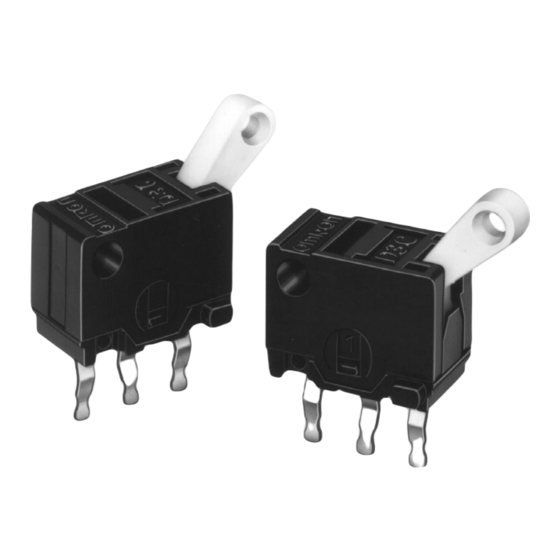
Ultra Subminiature Detection Switch
Ultra Subminiature Detection Switch
with Slide Mechanism and Lever
Actuator
Compact (8 6 4.2 mm (W H D)) and light
(approximately 0.3 g) with long, 3-mm stroke.
Built-in slide mechanism allows selection of
shorting or non-shorting timing to match the
application.
Ideal for a wide variety of applications, including
compact household appliances, audio equipment,
office machines, and telecommunications equip-
ment.
Ordering Information
Model Number Legend
D3C-j2j0
1
2
1.
Switching Timing
1:
Non-shorting
2:
Shorting
List of Models
Actuator
Rotary lever
D3C-1210
Specifications
Ratings
Electrical ratings 0.1 A at 30 VDC (resistive load)
Note: The ratings values apply under the following test conditions:
Ambient temperature: 20±2°C
Ambient humidity: 65±5%
Operating frequency: 30 operations/min
254
OF 1.28 N {130 gf}
Non-shorting Model
D3C-2210
2.
Maximum Oprating Force
1:
1.28 N {130 gf}
2:
0.39 N {40 gf}
Shorting Model
Non-shorting Model
D3C-1220
D3C
OF 0.39 N {40 gf}
Shorting Model
D3C-2220
Advertisement

Related Manuals for Omron D3C


Summary of Contents for Omron D3C
- Page 1 Ideal for a wide variety of applications, including compact household appliances, audio equipment, office machines, and telecommunications equip- ment. Ordering Information Model Number Legend D3C-j2j0 Switching Timing Maximum Oprating Force Non-shorting 1.28 N {130 gf} Shorting 0.39 N {40 gf}...
- Page 2 –20°C to 80°C (at ambient humidity of 60% max.) (with no icing) Ambient operating humidity 85% max. (for 5°C to 35°C) Weight Approx. 0.3 g Note: 1. The data given above are initial values. 2. For testing conditions, consult your OMRON sales representative. Contact Specifications Specification Slide Contact Material...
-
Page 3: Mounting Holes
1.6 dia Dimensions and Operating Characteristics Note: 1. All units are in millimeters unless otherwise indicated. 2. Unless otherwise specified, a tolerance of ±0.4 mm applies to all dimensions. Operating D3C-1210/-2210 direction (A) D3C-1220/-2220 Operating direction (B) PCB Dimensions 1-dia. hole +0.12... - Page 4 Precautions Refer to pages 26 to 31 for common precautions. Using Micro Loads Cautions Using a model for ordinary loads to open or close the contact of a micro load circuit may result in faulty contact. Use models that oper- Terminal Connection ate in the following range.
- Page 5 General Information General Information Correct Use Electrical Conditions Area Item Page Load Using Switches The switching capacity of a switch significantly differs depending on Selecting Correct Switch whether the switch is used to break an alternating current or a direct Electrical Load current.
-
Page 6: General Information
General Information General Information Contact Protective Circuit Apply a contact protective circuit (surge killer) to extend contact du- When a switch is used under high humidity, arcs resulting from cer- rability, prevent noise, and suppress the generation of carbide or ni- tain types of load (e.g., inductive loads) will generate nitrious oxides tric acid due to arc. -
Page 7: Mechanical Conditions
General Information General Information Mechanical Conditions Switching Speed and Frequency The switching frequency and speed of a switch have a great influ- Operating Stroke Setting ence on the performance of the switch. Pay attention to the follow- The setting of stroke is very important for a switch to operate with ing. -
Page 8: Terminal Connections
General Information General Information • Incorrect Do not modify the actuator. If the actuator is modified, excessive external force may be applied to the internal switch mechanism, Snap-back characteristics may change, and the switch may stop Shock operation functioning. • If an external actuator is used as an operating object, check the material and thickness of the lever to make sure that the force applied to the lever is within the permissible range. - Page 9 General Information General Information terminals, otherwise the terminal may be deformed or the housing Operation and Storage Environment may be damaged. Handling Wiring Work Do not apply oil, grease, or other lubricants to the sliding parts of a When wiring a switch, check the insulation distance between the switch.
- Page 10 General Information General Information Switch Trouble and Corrective Action Type Location Failure Possible cause Corrective action of failure Failures Contact Contact Dust and dirt on the contacts. Remove the cause of the problem, place related to l t d t f il failure the switch in a box, or use a sealed...