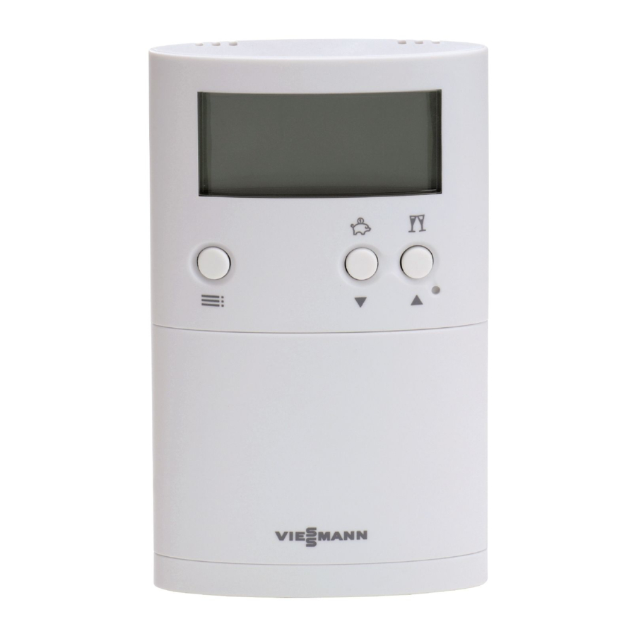
Viessmann VITOTROL 100 Installation Instructions For Contractors
Room temperature controller with digital time switch and wireless receiver
Hide thumbs
Also See for VITOTROL 100:
- Operating instructions for the system user (36 pages) ,
- Operating instructions manual (36 pages) ,
- Installation and service instructions manual (20 pages)
Table of Contents

Summary of Contents for Viessmann VITOTROL 100
-
Page 1: Installation Instructions
VIESMANN Installation instructions for contractors Vitotrol 100 Type UTDB-RF Room temperature controller with digital time switch and wireless receiver Part no: 7426 466, 7426 539 VITOTROL 100 Dispose after installation. 5418 852 GB 7/2009... -
Page 2: Safety Instructions
Safety instructions Please follow these safety instructions closely to prevent accidents and mate- rial losses. Safety instructions explained Working on the system Note ■ Isolate the system from the power sup- Details identified by the word "Note" con- ply and check that it is no longer 'live', tain additional information. -
Page 3: Table Of Contents
■ Connection to the control unit with plug gH............11 ■ Connection to the control unit with plug a-D............ 12 ■ General connection................... 13 Assembling the wireless receiver................. 14 Assembling the Vitotrol 100.................. 15 Commissioning the Vitotrol 100............... 16 Commissioning the wireless receiver.............. 17 Specification....................... 19... -
Page 4: Before Installation
Before installation Function The Vitotrol UTDB-RF controls the room temperature via the wireless receiver, by starting and stopping a heating circuit pump, for example. Installation location Clock thermostat ■ In the main living room on an internal wall opposite radiators. ■... -
Page 5: Opening The Vitotrol 100
Opening the Vitotrol 100 Fitting the wall mounting base Power is supplied by batteries (see chapter "Specification"). Always check reception prior to fitting to the wall (see page 17). -
Page 6: Fitting The Wireless Receiver
Fitting the wall mounting base (cont.) Fitting the wireless receiver Always check reception prior to installation (see page 17). - Page 7 Fitting the wireless receiver (cont.)
-
Page 8: Electrical Connection To The Control Unit
Electrical connection to the control unit Connection to the control unit with plug lH Insert the jumper between terminals L and COM in the wireless receiver. Recommended connecting cable ■ Cable with a cross-section of 1.5 mm² for 230 V~ Note Leave terminal NC in the wireless receiver free. -
Page 9: Connection To The Vitodens 100-W
Electrical connection to the control unit (cont.) Connection to the Vitodens 100-W Connection to terminals X1 1 L N A Terminals inside the wireless receiver B Terminals "X1" on the control unit Recommended connecting cable ■ Cable with a cross-section of 1.5 mm² for 230 V~ Note Leave terminal NC in the wireless... - Page 10 Electrical connection to the control unit (cont.) Connection to terminals X3 230V~ 1 2 3 A Terminals inside the wireless receiver B Terminals "X3" on the control unit 230 V cables and low voltage cables must be routed separately. Recommended connecting cable to the control unit ■...
-
Page 11: Connection To The Control Unit With Plug Gh
Electrical connection to the control unit (cont.) Connection to the control unit with plug gH Insert the jumper between terminals L and COM in the wireless receiver. Recommended connecting cable ■ Cable with a cross-section of 1.5 mm² for 230 V~ Note Leave terminal NC in the wireless receiver free. -
Page 12: Connection To The Control Unit With Plug A-D
Electrical connection to the control unit (cont.) Connection to the control unit with plug a-D 1. Remove jumper C between termi- nals 1 and 3 in plug a-D. 2. 230 V cables and low voltage cables must be routed separately. Recommended connecting cable to the control unit ■... -
Page 13: General Connection
Electrical connection to the control unit (cont.) General connection A Terminals inside the wireless B Components to be switched, e.g. receiver heating circuit pump Recommended connecting cable ■ Cable with a cross-section of 1.5 mm² for 230 V~... -
Page 14: Assembling The Wireless Receiver
Assembling the wireless receiver... -
Page 15: Assembling The Vitotrol 100
Assembling the Vitotrol 100... -
Page 16: Commissioning The Vitotrol 100
Commissioning the Vitotrol 100 1. Open flap. 2. Use a pointed object to press reset. 3. Select language with v/V. 4. Confirm with OK. 5. Set current time and date with v/ 6. Confirm with OK. -
Page 17: Commissioning The Wireless Receiver
Several Vitotrol 100 with wireless receiver can be installed in one building. Each pair is matched in the factory. If several Vitotrol 100 with wireless receiver are fitted in one building complex, never interchange a Vitotrol 100 and/or wireless receiver, as every Vitotrol 100 is matched to the wireless receiver allocated to it. - Page 18 10 s until A flashes. 7. Confirm with OK. "Send data" appears on the display. 2. Open the flap on the Vitotrol 100. The transfer takes 30 s. Q flashes during the transfer. 3. Press å twice.
-
Page 19: Specification
Specification Vitotrol 100 Rated voltage 3 V– 2 batteries LR 6/AA Ambient temperature ■ during operation 0 to 40 °C ■ during storage and transport -25 to 65 °C IP rating IP 20 to EN 60529 Wireless receiver Reception frequency... - Page 20 Viessmann Werke GmbH&Co KG Viessmann Limited D-35107 Allendorf Hortonwood 30, Telford Telephone: +49 6452 70-0 Shropshire, TF1 7YP, GB Fax: +49 6452 70-2780 Telephone: +44 1952 675000 www.viessmann.com Fax: +44 1952 675040 E-mail: info-uk@viessmann.com...


