Table of Contents
Advertisement
Quick Links
SCALANCE MUM856-1
SIMATIC NET
Industrial Remote Communication
- Remote Networks
SCALANCE MUM856-1
Operating Instructions
08/2021
C79000-G8976-C628-02
Preface
Security recommendations
Safety notices
Description of the device
Assembly and disassembly
Connecting up
Maintenance and cleaning
Troubleshooting
Technical specifications
Dimension drawings
Approvals
1
2
3
4
5
6
7
8
9
10
Advertisement
Table of Contents

Related Manuals for Siemens SIMATIC NET SCALANCE MUM856-1


Summary of Contents for Siemens SIMATIC NET SCALANCE MUM856-1
- Page 1 SCALANCE MUM856-1 Preface Security recommendations SIMATIC NET Safety notices Description of the device Industrial Remote Communication - Remote Networks SCALANCE MUM856-1 Assembly and disassembly Connecting up Operating Instructions Maintenance and cleaning Troubleshooting Technical specifications Dimension drawings Approvals 08/2021 C79000-G8976-C628-02...
- Page 2 Note the following: WARNING Siemens products may only be used for the applications described in the catalog and in the relevant technical documentation. If products and components from other manufacturers are used, these must be recommended or approved by Siemens. Proper transport, storage, installation, assembly, commissioning, operation and maintenance are required to ensure that the products operate safely and without any problems.
-
Page 3: Preface
DC, PoE, CLP slot, 1x DI and 1x DO, A- coded, IP65, -30… +60 °C You will find the article numbers for the Siemens products of relevance here in the following catalogs: • SIMATIC NET Industrial Communication / Industrial Identification, catalog IK PI •... - Page 4 Siemens Industry Online Support under the following entry ID: 84922825 (https://support.industry.siemens.com/cs/ww/en/view/84922825) SIMATIC NET manuals You will find SIMATIC NET manuals on the Internet pages of Siemens Industry Online Support: • using the search function: Link to Siemens Industry Online Support (https://support.industry.siemens.com/cs/ww/en/) Enter the entry ID of the relevant manual as the search item.
- Page 5 Siemens contact (Product return (https://support.industry.siemens.com/cs/ww/en/view/109479891)). Note the different national regulations. Device defective If a fault develops, send the device to your SIEMENS representative for repair. Repairs on-site are not possible. SCALANCE MUM856-1 Operating Instructions, 08/2021, C79000-G8976-C628-02...
- Page 6 Preface Trademarks The following and possibly other names not identified by the registered trademark sign ® registered trademarks of Siemens AG: SCALANCE, SINEMA, KEY-PLUG, C-PLUG License conditions Note Open source software Read the license conditions for open source software carefully before using the product.
-
Page 7: Table Of Contents
Table of contents Preface ..............................3 Security recommendations ........................9 Safety notices ............................17 Description of the device ........................19 Product characteristics ....................... 19 Device view ........................20 Scope of delivery ....................... 20 Accessories ........................22 LED display ........................24 Reset button ........................ - Page 8 Table of contents 10.1 Layout ..........................71 10.2 EC declaration of conformity ....................72 10.2.1 RoHS ..........................73 10.2.2 RED ........................... 73 10.2.2.1 Protection of health and safety................... 73 10.2.2.2 EMC ..........................74 10.2.2.3 Efficient use of the radio spectrum ..................75 10.2.3 Other technical standards ....................
-
Page 9: Security Recommendations
OpenVPN). • Separate connections correctly (WBM, SSH etc.). • Check the user documentation of other Siemens products that are used together with the device for additional security recommendations. • Using remote logging, ensure that the system protocols are forwarded to a central logging server. - Page 10 • Verify certificates based on the fingerprint on the server and client side to prevent "man in the middle" attacks. Use a second, secure transmission path for this. • Before sending the device to Siemens for repair, replace the current certificates and keys with temporary disposable certificates and keys, which can be destroyed when the device is returned.
- Page 11 Implementation Information Disclosure Vulnerability (for example, BEAST). • Ensure that the latest firmware version is installed, including all security-related patches. You can find the latest information on security patches for Siemens products at the Industrial Security (https://www.siemens.com/industrialsecurity) or ProductCERT Security Advisories (https://www.siemens.com/cert/en/cert-security-advisories.htm) website.
- Page 12 Security recommendations • Enable only those services that are used on the device, including physical ports. Free physical ports can potentially be used to gain access to the network behind the device. • For optimal security, use SNMPv3 authentication and encryption mechanisms whenever possible, and use strong passwords.
- Page 13 Security recommendations • Check whether use of the following protocols is necessary: – Telnet – HTTP – Broadcast pings – Non authenticated and unencrypted interfaces – ICMP (redirect) – LLDP – DHCP Options 66/67 – SNTP – NTP – TFTP –...
- Page 14 Security recommendations List of available services The following is a list of all available protocols and services as well as their ports through which the device can be accessed. The table includes the following columns: • Service The services that the device supports. •...
- Page 15 UDP/49155 RADIUS UDP/1812 Closed Closed ✓ ✓ ✓ UDP/1813 SFTP TCP/22 Outgoing Outgoing ✓ ✓ ✓ ✓ only only Siemens TCP/443 Outgoing Outgoing ✓ Optional ✓ Remote only only Service (cRSP/SRS) SINEMA RC HTTPS/443 Outgoing Outgoing ✓ ✓ ✓ ✓...
- Page 16 Security recommendations Layer 2 services Default status Configurable Open (when configured) ✓ LLDP Open (when configured) ✓ SIMATIC NET TIME Open (when configured) ✓ VLAN Open (when configured) ✓ SCALANCE MUM856-1 Operating Instructions, 08/2021, C79000-G8976-C628-02...
-
Page 17: Safety Notices
Safety notices CAUTION To prevent injury, read the manual before use. Read the safety notices Note the following safety notices. These relate to the entire working life of the device. You should also read the safety notices relating to handling in the individual sections, particularly in the sections "Installation"... - Page 18 Safety notices This equipment is suitable for use in Class I, Division 2, Groups A, B, C and D or non- hazardous locations only. This equipment is suitable for use in Class I, Zone 2, Group IIC or non-hazardous locations only.
-
Page 19: Description Of The Device
Description of the device Structure of the type designation The type designation of the device is made up of several parts that have the following meaning: Product characteristics Interfaces Functionality SCALANCE MUM856-1 Connectors for external antennas 4 x N-Connect Ethernet interface 1 x M12 Ethernet interface P1 LAN PoE, X-coded, 8-pin Power supply (direct) M12 interface, direct infeed, L-coded, 4-pin... -
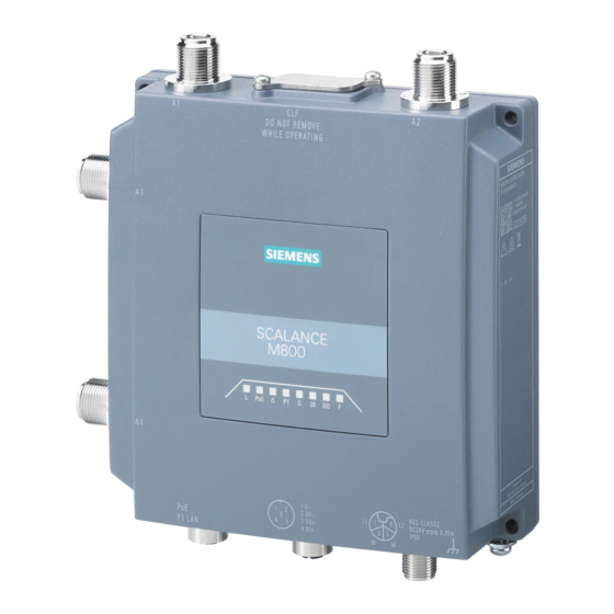
Page 20: Device View
Description of the device 3.2 Device view Device view ① A1 antenna port, female N-Connect type ② Screw-down cover: - for the reset button and - for the CLP slot ③ A2 antenna port, female N-Connect type ④ LED display ⑤... - Page 21 • One grounding screw • A product DVD Please check that the consignment you have received is complete. If the consignment is incomplete, contact your supplier or your local Siemens office. Note Not included with the product The following components do not ship with the product: •...
-
Page 22: Accessories
Description of the device 3.4 Accessories Accessories You will find further information on the accessories program for the M-800 in the Industry Mall (https://mall.industry.siemens.com). Type Properties Article number SCALANCE CLP 2GB M800 SINEMA RC 6GK5908-0UA00-0AA0 Mounting adapter DIN rail Adapter for mounting on a 35mm DIN rail... - Page 23 Description of the device 3.4 Accessories Type Properties Article number Antenna accessories SIMATIC NET N-Connect Flexible connecting cable e.g. for two RCoax male/male segments, various lengths 1 meter 6XV1875-5AH10 2 meters 6XV1875-5AH20 5 meters 6XV1875-5AH50 10 meters 6XV1875-5AN10 Flexible connecting cable e.g. for two RCoax segments, various lengths, railway applications 1 meter 6XV1875-5SH10...
-
Page 24: Led Display
Description of the device 3.5 LED display LED display Status Meaning Device turned off, no power supply. Green Device turned on, power supply present. The device is not supplied using PoE. Green The device is supplied using PoE. No VPN connection is established. Green All configured VPN connections are established. - Page 25 Description of the device 3.5 LED display Status Meaning There is no connection over the Ethernet interface P1. Green There is a connection over the Ethernet interface P1 (link). Flashing Data transfer over the Ethernet interface P1 green and yellow No reception Wrong PIN number or SIM card error Flashing red Signal strength very poor...
-
Page 26: Reset Button
Description of the device 3.6 Reset button Status Meaning No fault/error. The device is starting up or an error has occurred. Possible errors/faults: • Wrong PIN number • The inserted CLP has an invalid or incompatible configuration. Flashing red Firmware on CLP The device is performing a firmware update or downgrade. -
Page 27: Clp
• PLUG Configuration: The exchangeable storage medium only saves the configuration data of the device. • PLUG License: In addition to the configuration data, the removable data storage medium also contains a license that allows the use of Siemens Remote Services. SCALANCE MUM856-1 Operating Instructions, 08/2021, C79000-G8976-C628-02... - Page 28 Description of the device 3.7 CLP NOTICE Do not remove or insert a PLUG during operation! A PLUG may only be removed or inserted when the device is turned off. The device checks whether a PLUG is inserted at one second intervals. If it is detected that the PLUG was removed, there is a restart.
-
Page 29: Assembly And Disassembly
Assembly and disassembly Safety notices When installing the device, keep to the safety notices listed below. CAUTION Minimum distance to antennas Fit the device so that there is a minimum clearance of 20 cm between antennas and persons. NOTICE Improper mounting Improper mounting may damage the device or impair its operation. - Page 30 Assembly and disassembly WARNING When used in hazardous environments corresponding to Class I, Division 2 or Class I, Zone 2, the device must be installed in a cabinet or a suitable enclosure. WARNING If the device is installed in a cabinet, the inner temperature of the cabinet corresponds to the ambient temperature of the device.
- Page 31 Assembly and disassembly WARNING The equipment shall only be used in an area of not more than pollution degree 2, as defined in EN/IEC 60664-1, GB/T 16935.1. Safety notices when using according to FM If you use the device under FM conditions you must also keep to the following safety notices in addition to the general safety notices for protection against explosion: WARNING EXPLOSION HAZARD...
-
Page 32: Types Of Installation
Assembly and disassembly 4.1 Types of installation Types of installation Note • The device is only approved for operation in closed rooms. Note the following environmental conditions. • Antennas, in particular directional antennas, must be mounted in keeping with their characteristics (refer to the technical specifications of the antenna -->... -
Page 33: Din Rail Mounting
Assembly and disassembly 4.3 DIN rail mounting DIN rail mounting 4.3.1 Installation with the DIN rail mounting adapter The DIN rail mounting adapter is not included with the product, see Accessories (Page 22). Installation 1. Insert the SIM card, see section "SIM card (Page 49)". 2. - Page 34 Assembly and disassembly 4.3 DIN rail mounting 4. Press the device against the DIN rail until the DIN rail slider catch locks in place. 5. Connect the power supply, refer to the section "Power supply (Page 44)". 6. Fit the antennas, refer to the section "Antennas (Page 47)". Uninstalling 1.
-
Page 35: Mounting With Bracket Support
Assembly and disassembly 4.3 DIN rail mounting 4. Tilt the device forward and remove the device from the DIN rail. 5. Loosen the screws of the DIN rail mounting adapter completely. 4.3.2 Mounting with bracket support With the bracket support the device can be mounted on a DIN rail rotated through 90° The DIN rail mounting adapter and bracket holder are not included with the product, see Accessories (Page 22). - Page 36 Assembly and disassembly 4.3 DIN rail mounting Installation 1. Screw (M3, tightening torque 0.7 Nm) the bracket holder to the DIN rail mounting adapter . The mounting material ships with the product. 2. Screw (tightening torque 0.7 Nm) the bracket holder to the side of the device.
- Page 37 Assembly and disassembly 4.3 DIN rail mounting 5. Press the device against the DIN rail until the DIN rail slider catch locks in place. 6. Connect the power supply, refer to the section "Power supply (Page 44)". 7. Fit the antennas, refer to the section "Antennas (Page 47)". Uninstalling 1.
- Page 38 Assembly and disassembly 4.3 DIN rail mounting 4. Tilt the device forward and remove the device from the DIN rail. 5. Loosen the screws completely. SCALANCE MUM856-1 Operating Instructions, 08/2021, C79000-G8976-C628-02...
-
Page 39: Connecting Up
Connecting up Safety notices When connecting up the device, keep to the safety notices listed below. WARNING EXPLOSION HAZARD Replacing components may impair suitability for Class 1, Division 2 or Zone 2. WARNING EXPLOSION HAZARD Do not open the device when the supply voltage is turned on. Note Strain relief for the Ethernet cables In order to avoid mechanical stress on the Ethernet cables and resulting interruption of the... - Page 40 Connecting up Safety notices for operation with a power supply according to NEC Class 2 Operate the device with a power supply according to NEC Class 2. When connecting up the device, keep to the safety notices listed below. WARNING Power supply The device is designed for operation with a directly connectable safety extra low voltage (SELV) from a limited power source (LPS).
- Page 41 Connecting up Safety notices for operation with a power supply not complying with NEC Class 2 If you operate the device in a control cabinet, you can use a power supply that does not comply with NEC Class 2. When connecting up the device, keep to the safety notices listed below.
- Page 42 Connecting up NOTICE Suitable fuse for the power supply cables (corresponds to "Limited Energy") The current on the terminal may not exceed 3 A. Use a fuse for the power supply that is suitable for protection of AC/DC power supply circuits * and protects against currents >...
- Page 43 Connecting up Safety notices on use in hazardous areas General safety notices relating to protection against explosion WARNING EXPLOSION HAZARD Do not press the reset button if there is a potentially explosive atmosphere. WARNING EXPLOSION HAZARD Do not connect or disconnect cables to or from the device when a flammable or combustible atmosphere is present.
-
Page 44: Power Supply
Connecting up 5.1 Power supply Power supply Note Galvanic isolation of the power supply unit To ensure dielectric strength according to IEEE 802.3, the supplying 24 V power supply unit must be galvanically isolated with a dielectric strength of 1500 VAC. The galvanic isolation must also not be bridged by other devices connected to the same power supply unit. - Page 45 Connecting up 5.1 Power supply Position and pin assignment ① M12 Ethernet interface P1 LAN PoE, X-coded, 8-pin The power can also be supplied via this interface (Power over Ethernet). Pin assignment, see Ethernet (Page 46) ② M12 interface, direct infeed, L-coded, 4-pin The four-pin M12 socket has the following pin assignment: Color Signal...
-
Page 46: Ethernet
Connecting up 5.2 Ethernet Note The requirements of EN61000-4-5, "Surge Immunity Test" on power supply lines with 24 VDC are met only when a Blitzductor is used: 24 VDC: BVT AVD 24 type no. 918 422 Vendor: DEHN+SÖHNE GmbH+Co.KG, Hans Dehn Str. 1, Postfach 1640, D - 92306 Neumarkt, Germany Ethernet For connection to Industrial Ethernet at 10/100/1000 Mbps, the device has an M12 interface:... -
Page 47: Antennas
Connecting up 5.3 Antennas Antennas The SCALANCE MUM856-1 has 4 antenna ports of the type N-Connect female. The antenna used should have an impedance of about 50 ohms. Note Use the antennas from the range of accessories for the M87x device. You will find more detailed information in "Accessories (Page 22)". - Page 48 Connecting up 5.3 Antennas WARNING Danger due to lightning strikes Installing this lightning protector between an antenna and a SCALANCE M device is not adequate protection against a lightning strike. The LP798-1N lightening protector only works within the framework of a comprehensive lightning protection concept. If you have questions, ask a qualified specialist company.
-
Page 49: Sim Card
Connecting up 5.4 SIM card Frequency bands in Europe and other regions In Europe, America, Africa, Asia and Australia, the device supports the following frequency bands: • 5G: – SA: n1, n2, n3, n5, n7, n8, n12, n20, n28, n38, n40, n41, n48, n66, n71, n77, n78, –... - Page 50 Connecting up 5.4 SIM card Procedure 1. Remove the cover. 2. Press the tray with index finger and move it slightly upwards. The tray opens. 3. Insert the SIM card. 4. Close the tray. SCALANCE MUM856-1 Operating Instructions, 08/2021, C79000-G8976-C628-02...
-
Page 51: Grounding
Connecting up 5.5 Grounding 5. Lightly push the tray down with your finger until it locks into place. 6. Set the cover on again. Grounding EMC disturbances are diverted to ground via the functional ground. This ensures the immunity of the data transmission. The grounding screw is identified by the following symbol for the functional ground SCALANCE MUM856-1 Operating Instructions, 08/2021, C79000-G8976-C628-02... -
Page 52: Digital Input/Output
Connecting up 5.6 Digital input/output Protective earth/functional ground The connection of the reference potential surface with the protective earth system is normally in the cabinet close to the power feed-in. This earth conducts fault currents to ground safely and according to DIN/VDE 0100 is a protective earth to protect people, animals and property from too high contact voltages. - Page 53 Connecting up 5.6 Digital input/output Rules for user wiring • Always wire the digital input/output in pairs. • The maximum permitted cable length is <= 3 m. Position / Assignment Input ground Relay 24 V DC / 0.5 A Relay 24 V DC / 0.5 A 24 V DC Not connected SCALANCE MUM856-1...
-
Page 54: Inserting / Removing The Clp
Connecting up 5.7 Inserting / removing the CLP Inserting / removing the CLP Position The PLUG slot is at the top of the device enclosure under a cover, see Reset button (Page 26). Inserting the PLUG Follow the steps below to insert a PLUG in the device: 1. - Page 55 Connecting up 5.7 Inserting / removing the CLP Removing the PLUG Follow the steps below to remove a PLUG from the device: 1. Turn off the power to the device. 2. Loosen the screws ③ of the slot cover and remove the slot cover ②. As an alternative, you can loosen only one of the screws ③...
- Page 56 Connecting up 5.7 Inserting / removing the CLP SCALANCE MUM856-1 Operating Instructions, 08/2021, C79000-G8976-C628-02...
-
Page 57: Maintenance And Cleaning
Maintenance and cleaning WARNING Unauthorized repair of devices in explosion-proof design Risk of explosion in hazardous areas • Repair work may only be performed by personnel authorized by Siemens. WARNING Impermissible accessories and spare parts Risk of explosion in hazardous areas •... - Page 58 Maintenance and cleaning SCALANCE MUM856-1 Operating Instructions, 08/2021, C79000-G8976-C628-02...
-
Page 59: Troubleshooting
Downloading new firmware using TFTP without WBM and CLI Firmware The firmware is signed and encrypted. This ensures that only firmware created by Siemens can be downloaded to the device. You can download new firmware to the device using TFTP. To do this, the device does not need to be reachable either using Web Based Management (WBM) or using the Command Line Interface (CLI). -
Page 60: Restoring The Factory Settings
Troubleshooting 7.2 Restoring the factory settings Restoring the factory settings NOTICE Previous settings If you reset, all the settings you have made will be overwritten by factory defaults. NOTICE Inadvertent reset An inadvertent reset can cause disturbances and failures in a configured network with further consequences. - Page 61 Troubleshooting 7.2 Restoring the factory settings Via the configuration You will find detailed information on resetting the device parameters using the WBM and CLI in the configuration manuals: • Web Based Management, section "Restart" • Command Line Interface, section "Reset and Defaults" SCALANCE MUM856-1 Operating Instructions, 08/2021, C79000-G8976-C628-02...
- Page 62 Troubleshooting 7.2 Restoring the factory settings SCALANCE MUM856-1 Operating Instructions, 08/2021, C79000-G8976-C628-02...
-
Page 63: Technical Specifications
Technical specifications The following technical specifications apply to SCALANCE MUM856-1. Technical specifications Data transfer Ethernet transmission rate 10 Mbps, 100 Mbps, 1000 Mbp Wireless transmission rate • Downlink: up to 1000 Mbps • Uplink: up to 500 Mbps • Downlink: up to 1000 Mbps •... - Page 64 Technical specifications Technical specifications Electrical data Direct 24 V DC supply Supply voltage from 24 V DC Safety Extra Low Voltage (SELV) socket Type of current Permissi +/- 30 % 16.8 to 31.2 V DC ble range Design M12 socket, L-coded Properties Not galvanically isolated PoE to 24 V DC non-redundant design...
- Page 65 To establish a VPN (Virtual Private – Network), the following functions are available Up to 20 connections – IPsec VPN, OpenVPN (as client) – • SINEMA RC client • Proxy server • Siemens Remote Service (SRS) SCALANCE MUM856-1 Operating Instructions, 08/2021, C79000-G8976-C628-02...
- Page 66 Technical specifications Technical specifications Monitoring / diagnostics / maintenance • LEDs Display of operating statuses via the LED display. You will find additional information on this in the operating instructions of the device. • Logging Events can be logged for monitoring. •...
-
Page 67: Dimension Drawings
Dimension drawings Note Dimensions are specified in mm. Front view Width, height and dimensions for wall mounting SCALANCE MUM856-1 Operating Instructions, 08/2021, C79000-G8976-C628-02... - Page 68 Dimension drawings Side view Top view SCALANCE MUM856-1 Operating Instructions, 08/2021, C79000-G8976-C628-02...
- Page 69 Dimension drawings Rear view SCALANCE MUM856-1 Operating Instructions, 08/2021, C79000-G8976-C628-02...
- Page 70 Dimension drawings SCALANCE MUM856-1 Operating Instructions, 08/2021, C79000-G8976-C628-02...
-
Page 71: Approvals
Approvals for shipbuilding are not printed on the device type plate. Current approvals on the Internet You will find the current approvals for the product on the Internet pages of Siemens Industry Online Support at the following link: (https://support.industry.siemens.com/cs/ww/en/ps/15982/cert) -
Page 72: Ec Declaration Of Conformity
Process Automation DE-76187 Karlsruhe Germany You can find the current EU declaration of conformity for these products on the Internet pages under Siemens Industry Online Support (https://support.industry.siemens.com/cs/ww/en/ps/15914/cert). The products described in this document meet the requirements of the following EC directives: •... -
Page 73: Rohs
Approvals 10.2 EC declaration of conformity Name, address and identification American Certification Body, Inc. number of the notified body: 6731 Whittier Avenue, Suite C110 McLean, VA 22101 1588 Number of the EU type examination ATCB027001 certificate: 10.2.1 RoHS RoHS directive (restriction of the use of certain hazardous substances) The products described in these operating instructions meet the requirements of the EU directive 2011/65/EU for the restriction of the use of certain hazardous substances in electrical and electronic equipment. -
Page 74: Emc
Approvals 10.2 EC declaration of conformity 10.2.2.2 • EN 50121-3-2 Railway applications - Electromagnetic compatibility - Part 3-2: Rolling stock - Apparatus • EN 50121-4 Railway applications - Electromagnetic compatibility - Part 4: Interference emissions and immunity of signal telecommunications equipment •... -
Page 75: Efficient Use Of The Radio Spectrum
Approvals 10.2 EC declaration of conformity 10.2.2.3 Efficient use of the radio spectrum • ETSI EN 301 908-13 IMT cellular networks - Harmonized EN covering the essential requirements of article 3.2 of the R&TTE Directive - Part 13: Further developed universal terrestrial wireless access (E- UTRA) end devices (UE) •... -
Page 76: Declaration Of Conformity
Manchester M20 2UR United Kingdom You can find the current UK Declaration of Conformity for these products on the Internet pages under Siemens Industry Online Support (https://support.industry.siemens.com/cs/ww/en/ps/15914/cert) The SIMATIC NET product described in these operating instructions meets the requirements of the following directives: •... -
Page 77: Radio Equipment Regulations 2017
Approvals 10.3 UK Declaration of Conformity Applied standard: EN IEC 63000 Technical documentation for the assessment of electrical and electronic products with respect to restriction of hazardous substances 10.3.2 Radio Equipment Regulations 2017 10.3.2.1 Protection of health and safety • EN IEC 62368-1 Equipment for audio, video, information and communication technology - Part 1: Safety requirements •... -
Page 78: Efficient Use Of The Radio Spectrum
Approvals 10.3 UK Declaration of Conformity • ETSI EN 301 489-52 Electromagnetic Compatibility (EMC) standard for radio equipment and services; Part 52: Specific conditions for cellular communication mobile and portable (UE) radio and ancillary equipment • EN 55032 Electromagnetic compatibility of multimedia equipment – Emission requirements •... -
Page 79: Other Technical Standards
Approvals 10.4 Supplier’s declaration of conformity 10.3.3 Other technical standards • CISPR 11 Industrial, scientific and medical equipment - Radio-frequency disturbance characteristics - Limits and methods of measurement • CISPR 32 Electromagnetic compatibility of multimedia equipment. Emission requirements • CISPR 35 Electromagnetic compatibility of multimedia equipment - Immunity requirements •... -
Page 80: General Approvals
DE-76187 Karlsruhe Germany You can find the current Supplier's declaration of conformity for these products on the Internet pages under Siemens Industry Online Support (https://support.industry.siemens.com/cs/ww/en/ps/15853/cert) As required by the following Notices: • Radiocommunications (Compliance Labelling - Devices) Notice 2014 made under section 182 of the Radiocommunications Act 1992;... - Page 81 Area". You will find this document • on the data medium that ships with some devices. • on the Internet pages under Siemens Industry Online Support (https://support.industry.siemens.com/cs/ww/en/). Enter the document identification number "C234" as the search term. The markings of the electrical devices are:...
- Page 82 Cabling)Instrument 2015 made under section 407 of the Telecommunications Act 1997 You can find the current declaration of conformity for these products on the Internet pages under Siemens Industry Online Support (https://support.industry.siemens.com/cs/ww/en/ps/15914/cert) The products described in this document meet the requirements of the standards designated...
- Page 83 Approvals 10.5 General approvals Underwriters Laboratories Inc. complying with • UL 62368-1 • CSA C22.2 No. 62368-1 Report no. E115352 cULus Information Technology Equipment cULus Listed I. T. E. Underwriters Laboratories Inc. complying with • UL 61010-1 • UL 61010-2-201 •...
- Page 84 Approvals 10.5 General approvals SCALANCE MUM856-1 Operating Instructions, 08/2021, C79000-G8976-C628-02...
-
Page 85: Index
Index Accessories, 22 LED display A-coded, 44 M876-3, 24 Article numbers, 3 Power supply Button Connecting up, 44 Reset, 26 Product property, 19 Cables Reset device, 27, 60 Permissible lengths, 63 Configuration manuals, 61 Connecting up Digital input, 53 Safety notices SIM card, 50 for installation, 29 general, 17...