Siemens SIMATIC S7-400 Operating Instructions Manual
Industrial ethernet
Hide thumbs
Also See for SIMATIC S7-400:
- Reference manual (472 pages) ,
- Installation manual (316 pages) ,
- Hardware and installation manual (298 pages)
Table of Contents
Advertisement
Quick Links
SIMATIC NET
S7-400 - Industrial Ethernet
CP 443-1 OPC UA
Operating Instructions
01/2017
C79000-G8976-C427-02
___________________
Preface
___________________
Application and functions
___________________
LEDs and connectors
Installation, connecting up,
___________________
commissioning
___________________
Configuration and operation
Programming the OPC UA
___________________
client blocks
Diagnostics and
___________________
maintenance
___________________
Technical specifications
___________________
Approvals
___________________
Documentation references
1
2
3
4
5
6
7
A
B
Advertisement
Table of Contents

Related Manuals for Siemens SIMATIC S7-400


Summary of Contents for Siemens SIMATIC S7-400
- Page 1 ___________________ Preface ___________________ Application and functions ___________________ SIMATIC NET LEDs and connectors Installation, connecting up, ___________________ commissioning S7-400 - Industrial Ethernet CP 443-1 OPC UA ___________________ Configuration and operation Programming the OPC UA ___________________ client blocks Operating Instructions Diagnostics and ___________________ maintenance ___________________...
- Page 2 Note the following: WARNING Siemens products may only be used for the applications described in the catalog and in the relevant technical documentation. If products and components from other manufacturers are used, these must be recommended or approved by Siemens. Proper transport, storage, installation, assembly, commissioning, operation and maintenance are required to ensure that the products operate safely and without any problems.
-
Page 3: Preface
This description contains information on the following product: CP 443-1 OPC UA Article number 6GK7 443-1UX00-0XE0 Hardware product version 2 Firmware version V1.0.39 Communications processor for connection of the SIMATIC S7-400 to an OPC UA client and server Legend: ① X = placeholder for hardware product version ②... - Page 4 ● Editorial revision Replaced edition Release 07/2016 Current manual release on the Internet You will also find the current version of this manual on the Internet pages of Siemens Industry Online Support. Link: (https://support.industry.siemens.com/cs/ww/en/view/21862/man) Cross references In this manual there are often cross references to other sections.
- Page 5 You will find license conditions in the following document on the supplied data medium: ● OSS_CP4431-OPCUA_86.pdf Firmware The firmware is signed and encrypted. This ensures that only firmware created by Siemens can be downloaded to the device. Security information Siemens provides products and solutions with industrial security functions that support the secure operation of plants, systems, machines and networks.
- Page 6 Siemens contact. Keep to the local regulations. You will find information on returning the product on the Internet pages of Siemens Industry Online Support: Link: (https://support.industry.siemens.com/cs/ww/en/view/109479891)
-
Page 7: Table Of Contents
Table of contents Preface ..............................3 Application and functions ........................11 Application ..........................11 Communication services ......................11 Security functions ........................12 Other services and properties ....................14 Operating the CP in an H system ................... 14 Performance data ........................15 1.6.1 Configuration limits - hardware .................... - Page 8 Table of contents Interface configuration ......................43 4.6.1 Network settings........................43 4.6.2 Restart after detection of a duplicate IP address in the network ........... 44 Configuration of the CP in STEP 7 V5 ................... 45 4.7.1 "Addresses" tab ........................45 4.7.2 "SNMP"...
- Page 9 Table of contents FB234 UA_Disconnect ......................94 5.7.1 Function and call interface - UA_Disconnect ................94 5.7.2 Parameter - UA_Disconnect ....................95 FB235 UA_ReadList ....................... 95 5.8.1 Function and call interface - UA_ReadList................95 5.8.2 Parameter - UA_ReadList ....................... 96 5.8.3 UDT754 UANodeAdditionalInfo ....................
- Page 10 Table of contents CP 443-1 OPC UA Operating Instructions, 01/2017, C79000-G8976-C427-02...
-
Page 11: Application And Functions
Application and functions Application Application The CP is intended for operation in a SIMATIC S7-400 automation system. Via its Ethernet interface (1 x RJ45) the CP allows the S7-400 to function as an OPC UA client and an OPC UA server. -
Page 12: Security Functions
Application and functions 1.3 Security functions For information on configuring the server and client function refer to the section Configuration of the CP in STEP 7 V5 (Page 45). The CP supports the following specifications: ● IEC/TR 62541-1 (08-2012) OPC Unified Architecture - Part 1: Overview and Concepts ●... - Page 13 Application and functions 1.3 Security functions ● Authentication using certificates Authentication of the CP with OPC UA communications partners using certificates. The check of the certificates of the communications partner that are exchanged during authentication can be set to different levels separately for the server and client function. The CP supports the security profiles of the specification part 2, 4, 6, 7 und 12 of the OPC Foundation.
-
Page 14: Other Services And Properties
Application and functions 1.4 Other services and properties Other services and properties Other services and properties ● IP configuration The essential features of IP configuration for the CP: – The CP supports IP addresses according to IPv4. – Address assignment: The IP address, the subnet mask and the address of the default router can be set in the configuration. -
Page 15: Performance Data
Application and functions 1.6 Performance data Note the following restrictions: ● The CP does not support H communication. ● The CP does not support redundancy mechanisms. Operating the CP in an H system Each of the two redundant H CPUs has a CP plugged in which is assigned in each case to one of the two CPUs in the configuration ("General"... -
Page 16: Configuration Limits - Communication
Application and functions 1.6 Performance data 1.6.2 Configuration limits - communication OPC functions - OPC UA server In server mode the CP supports the following configuration limits: ● Number of connections to OPC UA clients Maximum of 10 connections to OPC UA clients ●... -
Page 17: Requirements For Use
Application and functions 1.7 Requirements for use OPC functions - OPC UA client In client mode the CP supports the following configuration limits: ● Number of sessions with OPC UA servers Up to 5 sessions with OPC UA servers at the same time Per server one or more sessions can be set up at the same time. - Page 18 Application and functions 1.7 Requirements for use ● Fault tolerant CPUs CPU 400H as of firmware version V6.0.5 H-CPUs with a firmware version <V6.0.5 must be upgraded where possible. ● SIMATIC PCS 7 CPUs SIMATIC PCS 7 CPU 410-5H as of firmware version V8.1 CPUs with a firmware version <V8.1 must be upgraded where possible.
-
Page 19: Configuration
SCT is called in the configuration directly from within STEP 7 V5. Finding the components to be installed for the CP You can find the components on the Siemens Industry Online Support website at the following addresses: ● Service Pack 4 for STEP 7 V5.5 Link: (https://support.industry.siemens.com/cs/ww/en/view/93842624) -
Page 20: Programming
● Update 2 for STEP 7 Professional V14 Link: (https://support.industry.siemens.com/cs/ww/en/ps/14673/dl) ● SCT V4.2 Link: (https://support.industry.siemens.com/cs/ww/en/view/109738442) You can find the the current version and additional information on the Siemens Industry Online Support website at the following address: Link: (https://support.industry.siemens.com/cs/ww/en/ps/15326) Installation of the HSP In STEP 7 V5 Install the HSP in STEP 7 / HW Config with the "Options"... -
Page 21: Web Browser For Access Using Https
Application and functions 1.8 Configuration examples Configuration tool for programming You program the user program of the CPU and the program blocks for the OPC UA client function in STEP 7. Refer to the information on the required STEP 7 version in the section Configuration (Page 19). - Page 22 Application and functions 1.8 Configuration examples Logging process data as OPC UA server In this configuration as the OPC UA server, the CP makes manufacturing or process data from S7 stations available to a higher-level system. Higher level systems can, for example, be PC stations with an OPC UA application, database systems or HMI systems from third-party manufacturers.
- Page 23 Application and functions 1.8 Configuration examples Forwarding of data from the manufacturing planning as OPC UA server and client In this configuration as the OPC UA server, the CP adopts setting data for manufacturing from a higher-level production control system. When necessary the manufacturing data can be preprocessed on the CPU.
- Page 24 Application and functions 1.8 Configuration examples Horizontal data exchange as OPC UA client and server In this configuration as OPC UA server and client, the CP exchanges data with other process stations or PC stations. The process stations can also be programmable controllers from third-party manufacturers that support the required OPC UA functions.
-
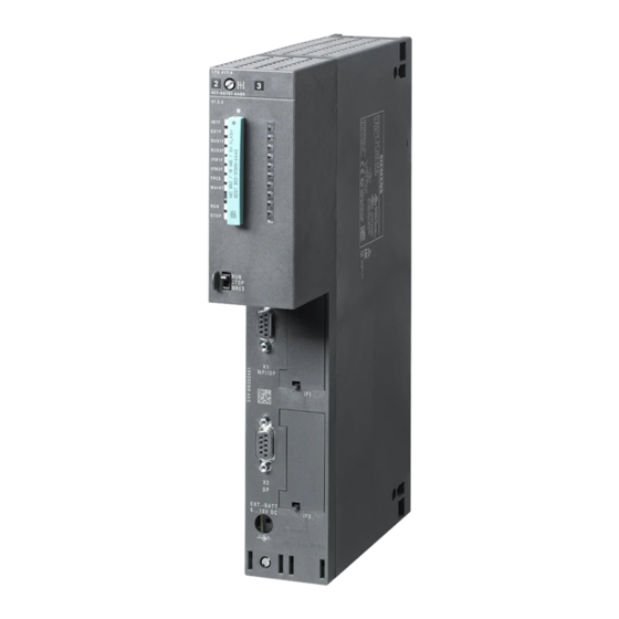
Page 25: Leds And Connectors
LEDs and connectors LEDs LEDs The display on the front panel consists of the following LEDs that indicate the operating mode and communications status. Figure 2-1 LEDs of the CP The LEDs have the following meaning: LED name Meaning INTF Internal error EXTF External error... - Page 26 LEDs and connectors 2.1 LEDs Table 2- 2 Operating statuses, errors/faults, OPC configuration, firmware update INTF EXTF BUSF SERVER CLIENT STOP Meaning (red) (red) (red) (green) (green) (green (yel- low) Operating status Loading the firmware after power ON Starting up (STOP->RUN) Running (RUN) Stopping (RUN->STOP) Stopped (STOP)
- Page 27 LEDs and connectors 2.2 Power supply INTF EXTF BUSF SERVER CLIENT STOP Meaning (red) (red) (red) (green) (green) (green (yel- low) Firmware update Firmware activation during startup: Loading using the Firmware Loader is active. Note: Does not apply to loading via the update center in Web diagnostics.
-
Page 28: Power Supply
LEDs and connectors 2.2 Power supply Power supply Power supply The CM is supplied with power from the backplane bus. It does not require a separate power supply. Ethernet interface X1P1 Ethernet interface The CP has an Ethernet interface (RJ-45 jack) complying with the gigabit standard IEEE 802.3ab. -
Page 29: Installation, Connecting Up, Commissioning
Installation, connecting up, commissioning Important notes on using the device Safety notices on the use of the device Note the following safety notices when setting up and operating the device and during all associated work such as installation, connecting up or replacing the device. 3.1.1 Safety requirements for installation WARNING... - Page 30 Installation, connecting up, commissioning 3.1 Important notes on using the device WARNING The device may only be operated in an environment with pollution degree 1 or 2 (see IEC 60664-1). WARNING EXPLOSION HAZARD The device must not be opened. WARNING Power supply The equipment is designed for operation with Safety Extra-Low Voltage (SELV) by a Limited Power Source (LPS).
-
Page 31: Notes On Use In Hazardous Areas According To Atex / Iecex
Installation, connecting up, commissioning 3.1 Important notes on using the device 3.1.3 Notes on use in hazardous areas according to ATEX / IECEx WARNING Requirements for the cabinet To comply with EC Directive 94/9 (ATEX95) or the conditions of IECEx, this enclosure or cabinet must meet the requirements of at least IP54 in compliance with EN 60529. -
Page 32: Notices On Use In Hazardous Areas According To Fm
Installation, connecting up, commissioning 3.2 Installing and connecting up the CP 3.1.5 Notices on use in hazardous areas according to FM WARNING EXPLOSION HAZARD You may only connect or disconnect cables carrying electricity when the power supply is switched off or when the device is in an area without inflammable gas concentrations. This equipment is suitable for use in Class I, Division 2, Groups A, B, C and D or non- hazardous locations only. -
Page 33: Commissioning The Cp
Installation, connecting up, commissioning 3.3 Commissioning the CP 3. Secure the CP with screws. 4. Turn on the power supply. 5. Connect the CP to Industrial Ethernet via the RJ-45 jack. For operation on the Ethernet network, not section Network settings (Page 43). Result: The CP is installed in the rack and the interface has been networked. - Page 34 Installation, connecting up, commissioning 3.3 Commissioning the CP CP 443-1 OPC UA Operating Instructions, 01/2017, C79000-G8976-C427-02...
-
Page 35: Configuration And Operation
Configuration and operation Controlling the mode Changing the mode You can change the mode of the CP between RUN and STOP using STEP 7 or using STEP 7 special diagnostics. STOP → RUN During startup, the CP adopts configured and/or downloaded data in the work memory and then changes to RUN mode. - Page 36 ● Keep the firmware up to date. Check regularly for security updates of the firmware and use them. ● Check regularly for new features on the Siemens Internet pages. – Here you will find information on network security: Link: (http://www.siemens.com/industrialsecurity) –...
- Page 37 Configuration and operation 4.2 Security recommendations ● Protection of the passwords of the OPC UA client program blocks Protect the passwords stored in data blocks for the client blocks from being viewed. The procedure is described below. ● Logging function Enable the function in the Security configuration and check the logged events regularly for unauthorized access.
- Page 38 Configuration and operation 4.2 Security recommendations Protocols Secure and non-secure protocols ● Only activate protocols that you require to use the system. ● Use secure protocols when access to the device is not prevented by physical protection measures. The NTP protocol provides a secure alternative with NTP (secure). Table: Meaning of the column titles and entries The following table provides you with an overview of the open ports on this device.
-
Page 39: Overview Of The Configuration
Configuration and operation 4.3 Overview of the configuration Protocol / function Port number (pro- Default of the port Port status Authentication tocol) 123 (TCP) Closed Open after configuration HTTPS 443 (TCP) Closed Open after configuration SNMP 161 (UDP) Open Open after configuration Yes (with SNMPv3) Overview of the configuration Configuration in STEP 7... -
Page 40: Data Types
Configuration and operation 4.5 Data types The symbol name is included in the NodeID of an item as part of the identifier, see section Properties of the OPC UA server (Page 76). Syntax of the symbol names For the names of symbols to be used for OPC UA, the ASCII characters no. 32 .. 126 (0x20 .. - Page 41 Configuration and operation 4.5 Data types Table 4- 1 Data types Size [bit], Area Data type Remark Operand area of type the CPU SIMATIC S7 IEC 61131-3 OPC UA 0 .. 255 BOOL BOOL Boolean 0 = false I, Q, PI, PQ, M, 1 ..
- Page 42 Configuration and operation 4.5 Data types You will find a general description of the coding of the data types in the STEP 7 online help. Special features of complex data types With the complex data types used by the OPC UA function of the CP. the special coding rules apply that are described below.
-
Page 43: Interface Configuration
Configuration and operation 4.6 Interface configuration Parameter types The parameter types "TIMER" and "COUNTER" are only supported for the OPC UA server of the CP. Interface configuration 4.6.1 Network settings Transmission speed If you want to use transmission speed 1 Gbps, leave the interface set to "Automatic setting". The connection partner must also be configured with "1 Gbps full duplex"... -
Page 44: Restart After Detection Of A Duplicate Ip Address In The Network
Configuration and operation 4.6 Interface configuration You will find information on the currently used network settings here: ● In special diagnostics under the diagnostics object "Industrial Ethernet" in the "Network Connection" group box ● in STEP 7 with the menu command "PLC > Module Information" ●... -
Page 45: Configuration Of The Cp In Step 7 V5
Configuration and operation 4.7 Configuration of the CP in STEP 7 V5 Behavior when the CP starts up If duplicate addressing is detected when the CP starts up, the CP remains in STOP. The bus fault LED is lit and a diagnostics buffer entry is generated. The CP only starts up after the duplicate addressing problem has been eliminated. - Page 46 Configuration and operation 4.7 Configuration of the CP in STEP 7 V5 Configuration Requirement for configuring the parameters described below is the activation of the security functions, see section "Security" Tab (Page 47). If the security functions are enabled, you have the following selection and setting options. "Enable SNMP"...
-
Page 47: Security" Tab
Configuration and operation 4.7 Configuration of the CP in STEP 7 V5 See also Configuration in the SCT (Page 55) 4.7.3 "Security" Tab Enabling the Security functions In this tab, you can enable the Security functions of the CP. The enabling of the Security functions releases additional parameters in the following further tabs of the properties dialog. -
Page 48: Diagnostics" Tab
Configuration and operation 4.7 Configuration of the CP in STEP 7 V5 Start of security configuration If you click the "Run" button, the SCT opens. Security settings in SCT Relevant SCT tab Make the Security settings of the CP in the SCT in the flowing tabs: ●... -
Page 49: Web" Tab
When you click the "Run" button NCM Diagnostics is started as a separate program. As an alternative to starting the program from the Properties dialog, open the program with: Windows Start menu> Program group Siemens Automation > SIMATIC > STEP 7 > NCM S7 > Diagnostics "Start of Web diagnostics"... -
Page 50: Time-Of-Day Synchronization" Tab
Configuration and operation 4.7 Configuration of the CP in STEP 7 V5 "Options of Web diagnostics" ● "Download firmware via Web" By enabling the option, the function for downloading the firmware of the CP from the download center is enabled in the Web server. ●... - Page 51 Configuration and operation 4.7 Configuration of the CP in STEP 7 V5 The CP supports the following methods of time-of-day synchronization: ● SIMATIC mode The SIMATIC mode cannot be configured. If you leave the time-of-day synchronization via NTP disabled, the SIMATIC mode is enabled automatically on the CP.
-
Page 52: Options" Tab: Effects Of Protection Levels
Configuration and operation 4.7 Configuration of the CP in STEP 7 V5 "Security configuration" If the security functions are enabled, further settings are possible. ● "Expanded NTP configuration" Enable this option to be able to configure the security functions for time-of-day synchronization. -
Page 53: Opc Ua" Tab
OPC UA name space of the station and must be unique within the project for every CP. The default application name for the CP is: Siemens:SIMATIC-S7-CP443-1:OPC-UA Change the application name so that the name is unique for every CP in the STEP 7 project. - Page 54 Configuration and operation 4.7 Configuration of the CP in STEP 7 V5 ● "Default port" Here, you can change the port number of the application. As default port number 4840 is used, the standard TCP port for the OPC UA binary protocol. Permitted port numbers are as follows: –...
-
Page 55: Configuration In The Sct
Configuration and operation 4.7 Configuration of the CP in STEP 7 V5 "Security configuration" ● "Start of the OPC UA security settings" With the "Run" button, you open the SCT dialog for configuring the Security functions of the server application. For details, see section Configuration in the SCT (Page 55). - Page 56 Configuration and operation 4.7 Configuration of the CP in STEP 7 V5 The settings made here are downloaded to the station with the configuration data and take effect when the station starts up. For information on authentication with a logging server, refer to the section Handling certificates (Page 59).
- Page 57 Configuration and operation 4.7 Configuration of the CP in STEP 7 V5 – Best possible procedure Depending on the settings on the communications partner (client), the CP selects the procedure with the the highest possible security. This may be: - Sign - Sign and encrypt ●...
- Page 58 Configuration and operation 4.7 Configuration of the CP in STEP 7 V5 Regardless of these exceptions, to establish a connection, at least the following requirements must be met: – The application URI sent by the requesting client must match the URI of the server application of the CP.
-
Page 59: Handling Certificates
Opening SCT Open the SCT in one of the following alternative ways: ● From the Windows Start menu: Siemens Automation > SIMATIC > Security > Security Configuration Tool ● From STEP 7 / HW Config "Edit > Security Configuration Tool". -
Page 60: Configuration Of The Cp In Step 7 Professional
Configuration and operation 4.8 Configuration of the CP in STEP 7 Professional No certificate when the Security functions are disabled. If the Security functions of the CP are disabled in the STEP 7 project, no certificate will be generated for the CP. If you use the CP as an OPC UA server, check whether the UA clients you are using necessarily demand a certificate. -
Page 61: Ethernet Interface" Parameter Group
Configuration and operation 4.8 Configuration of the CP in STEP 7 Professional The following actions are only possible when either the CPU or the CP is in the STOP state: – Changing the operating status of the CP (RUN → STOP) –... -
Page 62: Opc Ua" Parameter Group
Configuration and operation 4.8 Configuration of the CP in STEP 7 Professional Time synchronization ● Security disabled If the security functions are disabled, configure time-of-day synchronization of the CP at this point. If the CP cannot be synchronized with NTP, the SIMATIC method is used automatically. -
Page 63: I/O Addresses" Parameter Group
Configuration and operation 4.8 Configuration of the CP in STEP 7 Professional ● SNMPv3 Available only when security functions are enabled For information on the configuring SNMPv3, refer to the section Security > "SNMP" (Page 65). Configuration ● "Enable SNMP" If the option is enabled, communication via SNMPv1 is enabled on the CP. -
Page 64: Security > "Time-Of-Day Synchronization
Configuration and operation 4.8 Configuration of the CP in STEP 7 Professional ● S7 communication ● Certificate manager Via the local certificate manager, you can import and export certificates for the CP. You will find help on the certificate manager in the STEP 7 information system ate following location: "Editing devices and networks >Configuring devices and networks >Configure networks >... -
Page 65: Security > "Snmp
Configuration and operation 4.8 Configuration of the CP in STEP 7 Professional NTP configuration You will find help on the parameters in the STEP 7 information system. ● NTP server You configure the NTP servers in the table of NTP servers. If you use "NTP (secure)", the servers of the type NTP (secure) that you configured in the global security settings are also displayed here. -
Page 66: Security > "Web Server
Configuration and operation 4.8 Configuration of the CP in STEP 7 Professional SNMPv1 The community strings need to be sent along with queries to the CP via SNMPv1. ● "Reading community string" The string is required for read access. Leave the preset string "public" or configure a string. ●... -
Page 67: Security > "Opc Ua
OPC UA name space of the station and must be unique within the project for every CP. The default application name for the CP is: Siemens:SIMATIC-S7-CP443-1:OPC-UA Change the application name so that the name is unique for every CP in the STEP 7 project. - Page 68 Configuration and operation 4.8 Configuration of the CP in STEP 7 Professional OPC UA server General ● Activate OPC UA server Enable this option to enable the function of an OPC UA server on the CP. The following parameters are displayed: –...
- Page 69 Configuration and operation 4.8 Configuration of the CP in STEP 7 Professional ● Minimum sampling interval Here you set the minimum sampling interval at which the CP scans the process data of the configured CPU symbols. The sampling interval is limited to a minimum value of 100 milliseconds to reserve adequate time for other processes that access the CPU via the backplane bus of the station.
- Page 70 Configuration and operation 4.8 Configuration of the CP in STEP 7 Professional The security policy is a combination of one of the following security profiles and a security procedure. ● Security profile – No security profile – Basic128Rsa15 This corresponds to the Security profile "Basic128Rsa15" of the OPC UA specification.
- Page 71 Configuration and operation 4.8 Configuration of the CP in STEP 7 Professional Certificate validation Here you set the options for checking the certificates of the communications partners for the UA server function of the CP. ● Check certificates The CP always checks the certificate of the communications partner. If the partner certificate is invalid or is not trustworthy, communication is aborted.
-
Page 72: Security > "S7 Communication
Configuration and operation 4.8 Configuration of the CP in STEP 7 Professional Certificate validation For information on the certificate validation, refer to the relevant table of the OPC UA server above. Note Special features for the client application The value of the parameter "CheckServerCertificate" that you programmed in the connection information (UASessionConnectInfo) for the client program block "UA_Connect"... -
Page 73: Security > "Certificate Manager
Configuration and operation 4.8 Configuration of the CP in STEP 7 Professional 4.8.12 Security > "Certificate manager" Assignment of certificates If you use OPC UA communication with authentication for the CP, you need to import certificates of the communications partner into the STEP 7 project and download them to the CP with the configuration data: 1. - Page 74 Configuration and operation 4.8 Configuration of the CP in STEP 7 Professional If the CP communicates with non-Siemens partners when the security functions are enabled, the relevant certificates of the communications partners must be exchanged. To do this, follow the steps below: 1.
- Page 75 Configuration and operation 4.8 Configuration of the CP in STEP 7 Professional You export the certificate of the CP for communications partners from third-party vendors in much the same way as when importing (see above). Follow the steps outlined below: 1.
-
Page 76: Properties Of The Opc Ua Server
The CP as UA server makes the namespace index 3 available. ● Namespace Example of the name space of the CPU symbols in the S7-400 with CP 443-1 OPC UA: http://www.siemens.com/simatic-classic-s7-opcua ● Application name The name of the server application preset by STEP 7 is: Siemens:SIMATIC-S7-CP443-1:OPC-UA The name must must e adapted for every CP in the STEP 7 project individually (unique). - Page 77 Configuration and operation 4.9 Properties of the OPC UA server If there is power down, all data and connection information of subscriptions is lost. After restarting the server, the client needs to re-establish the connection and set up the subscriptions again. Connection abort If a connection between the CP as UA server and an OPC UA client aborts, the session is retained according to the OPC specification.
- Page 78 Configuration and operation 4.9 Properties of the OPC UA server CP 443-1 OPC UA Operating Instructions, 01/2017, C79000-G8976-C427-02...
-
Page 79: Programming The Opc Ua Client Blocks
Programming the OPC UA client blocks Program blocks for the OPC UA client Overview of the program blocks for the OPC UA client function The program blocks (FBs) listed below are available in the following block library for the OPC UA client function of the CP. - Page 80 Programming the OPC UA client blocks 5.1 Program blocks for the OPC UA client ● FB234 UA_Disconnect Terminates the connection of a current session with an OPC UA server. ● FB235 UA_ReadList Using the list of node handles, reads the data from nodes of the connected server. –...
- Page 81 Programming the OPC UA client blocks 5.1 Program blocks for the OPC UA client Creating the SFCs in STEP 7 Professional 1. Create the system functions by opening an organization block in the block directory of the CPU, for example OB1. 2.
-
Page 82: Time Monitoring Of The Blocks
Programming the OPC UA client blocks 5.2 Time monitoring of the blocks Figure 5-1 Calling the client program blocks and their interaction If the connection is no longer required, release the handles on the server again using the block UA_NodeReleaseHandleList. This deletes the handles on the server. The connection is terminated with UA_Disconnect and the session is ended. -
Page 83: Fb230 Ua_Connect
Programming the OPC UA client blocks 5.3 FB230 UA_Connect The minimum value of SessionTimeout" is 30 seconds. If the value is exceeded, the connection is terminated. The parameter allows a server to to reduce bound resources if the client does not use the session for a longer period of time. -
Page 84: Parameter - Ua_Connect
Programming the OPC UA client blocks 5.3 FB230 UA_Connect Call interface Figure 5-2 Call interface in FBD representation 5.3.2 Parameter - UA_Connect Block parameters The following table explains the formal parameters of the program block. Table 5- 1 Parameters of the block UA_Connect Parameter Declaration S7 data type Range of values... -
Page 85: Udt751 Uasessionconnectinfo
Programming the OPC UA client blocks 5.3 FB230 UA_Connect Parameter Declaration S7 data type Range of values Meaning Error BOOL 0, 1 Error code 0: No error • 1: An error has occurred. See "" parameter • "ErrorID". ErrorID DWORD See “Meaning”... - Page 86 Programming the OPC UA client blocks 5.3 FB230 UA_Connect Parameter S7 data type Range of val- Meaning ClientCertificate- STRING 0 .. 254 char- Name of the client certificate Name acters The parameter is inserted by STEP 7. ServerUri STRING 0 .. 254 char- Server address (URI) that is also stored in the acters server certificate.
-
Page 87: Udt752 Uauseridentitytoken
Programming the OPC UA client blocks 5.4 FB231 UA_NamespaceGetIndex Parameter S7 data type Range of val- Meaning MonitorConnection TIME 5000 .. Connection monitoring time (milliseconds) 86 400 000 Time without data traffic after which the client checks the connection to the server by send- ing a frame. -
Page 88: Parameter - Ua_Namespacegetindex
Specifies the address (name space URI) of the ters target server Example of the name space of the CPU sym- bols in the S7-400 with CP 443-1 OPC UA: http://www.siemens.com/simatic-classic-s7- opcua Timeout TIME 5000 .. 120000 Maximum time for establishing the connection in milliseconds. -
Page 89: Fb232 Ua_Nodegethandlelist
Programming the OPC UA client blocks 5.5 FB232 UA_NodeGetHandleList Parameter Declaration S7 data type Range of values Meaning Done BOOL 0, 1 Status parameter for block processing 0: Block execution aborted, not yet complet- • ed or not yet started 1: Block processing completed without er- •... -
Page 90: Parameter - Ua_Nodegethandlelist
Programming the OPC UA client blocks 5.5 FB232 UA_NodeGetHandleList Call interface Figure 5-4 Call interface in FBD representation 5.5.2 Parameter - UA_NodeGetHandleList Block parameters The following table explains the formal parameters of the program block. Table 5- 5 Parameters of the block UA_NodeGetHandleList Parameter Declaration S7 data type Range of values... - Page 91 Programming the OPC UA client blocks 5.5 FB232 UA_NodeGetHandleList Parameter Declaration S7 data type Range of values Meaning NodeHdls ARRAY of 0 .. 4 294 967 295 Array of the handles that the OPC UA server DWORD assigns as the reply to the client's query. The handles serve to uniquely identify the item on the server.
-
Page 92: Udt753 Uanodeid
Programming the OPC UA client blocks 5.6 FB233 UA_NodeReleaseHandleList 5.5.3 UDT753 UANodeID UANodeID The following table shows the meaning of the parameters of UANodeID to identify the target node on the OPC UA server. UANodeID supplies the parameter "NodeIDs" of the UA_NodeGetHandleList"... -
Page 93: Parameter - Ua_Nodereleasehandlelist
Programming the OPC UA client blocks 5.6 FB233 UA_NodeReleaseHandleList Call interface Figure 5-5 Call interface in FBD representation 5.6.2 Parameter - UA_NodeReleaseHandleList Block parameters The following table explains the formal parameters of the program block. Table 5- 7 Parameters of the block UA_NodeReleaseHandleList Parameter Declaration S7 data type Range of values... -
Page 94: Fb234 Ua_Disconnect
Programming the OPC UA client blocks 5.7 FB234 UA_Disconnect Parameter Declaration S7 data type Range of values Meaning / remarks Error BOOL 0, 1 Error code 0: No error • 1: An error has occurred. See "" parameter • "ErrorID". ErrorID DWORD See “Meaning”... -
Page 95: Parameter - Ua_Disconnect
Programming the OPC UA client blocks 5.8 FB235 UA_ReadList 5.7.2 Parameter - UA_Disconnect Block parameters The following table explains the formal parameters of the program block. Table 5- 8 Parameters of the block UA_Disconnect Parameter Declaration S7 data type Range of values Meaning Execute BOOL... -
Page 96: Parameter - Ua_Readlist
Programming the OPC UA client blocks 5.8 FB235 UA_ReadList You program the attributes to be read in a UDT "UANodeAdditionalInfo" that is referenced by the input parameter "NodeAddInfos". The handles required at the input parameter "NodeHdls" are read from array of the output parameter "NodeHdls"... - Page 97 Programming the OPC UA client blocks 5.8 FB235 UA_ReadList Parameter Declaration S7 data type Range of values Meaning Timeout TIME 5000 .. 120000 Maximum time for establishing the connection in milliseconds. If the value is exceeded, pro- cessing of the block is aborted with error num- ber B0007001.
-
Page 98: Udt754 Uanodeadditionalinfo
Programming the OPC UA client blocks 5.8 FB235 UA_ReadList 5.8.3 UDT754 UANodeAdditionalInfo UANodeAdditionalInfo Specifies the attribute of the item and the index range for the block parameter "NodeAddInfos". Table 5- 10 Parameters of UDT UANodeAdditionalInfo Parameter S7 data type Range of values Meaning AttributeID WORD... -
Page 99: Udt757 Uaanypointer
Programming the OPC UA client blocks 5.8 FB235 UA_ReadList Rules: If IndexRangeCount = 1 is used, the following rules apply to programming the index range: ● StartinIndex and EndIndex must be assigned. ● For access to more than one element the StartIndex must be lower than the EndIndex. If this is not the case, this causes an error with the number 80360000. - Page 100 Programming the OPC UA client blocks 5.8 FB235 UA_ReadList Parameter S7 data type Range of values Meaning MemArea WORD See “Meaning” Memory area Enter either the number of a DB or a memory area. If you specify a memory area, enter a zero in "DB_Number".
-
Page 101: Udt756 Uatimestamp
Programming the OPC UA client blocks 5.9 FB236 UA_WriteList Table 5- 14 Coding of the memory area Hexadecimal code Area Description b#16#80 Memory area of the I/O b#16#81 Memory area of the inputs b#16#82 Memory area of the outputs b#16#83 Memory area of the bit memory b#16#84 Data block... -
Page 102: Parameter - Ua_Writelist
Programming the OPC UA client blocks 5.9 FB236 UA_WriteList Call interface Figure 5-8 Call interface in FBD representation 5.9.2 Parameter - UA_WriteList Block parameters The following table explains the formal parameters of the program block. Table 5- 16 Parameters of the block UA_WriteList Parameter Declaration S7 data type Range of values... - Page 103 Programming the OPC UA client blocks 5.9 FB236 UA_WriteList Parameter Declaration S7 data type Range of values Meaning Variables IN_OUT ARRAY See “Meaning” Reference to the data to be written. For infor- [1..1] of UDT mation on the structure of the UDT, see UDT757 UAAnyPointer (Page 105).
-
Page 104: Udt754 Uanodeadditionalinfo
Programming the OPC UA client blocks 5.9 FB236 UA_WriteList 5.9.3 UDT754 UANodeAdditionalInfo UANodeAdditionalInfo Specifies the attribute of the item and the index range for the block parameter "NodeAddInfos". Table 5- 17 Parameters of UDT UANodeAdditionalInfo Parameter S7 data type Range of values Meaning AttributeID WORD... -
Page 105: Udt757 Uaanypointer
Programming the OPC UA client blocks 5.9 FB236 UA_WriteList Rules: If IndexRangeCount = 1 is used, the following rules apply to programming the index range: ● StartinIndex and EndIndex must be assigned. ● For access to more than one element the StartIndex must be lower than the EndIndex. If this is not the case, this causes an error with the number 80360000. - Page 106 Programming the OPC UA client blocks 5.9 FB236 UA_WriteList Parameter S7 data type Range of values Meaning MemArea WORD See “Meaning” Memory area Enter either the number of a DB or a memory area. If you specify a memory area, enter a zero in "DB_Number".
-
Page 107: Error Numbers
Programming the OPC UA client blocks 5.10 Error numbers Table 5- 21 Coding of the memory area Hexadecimal code Area Description b#16#80 Memory area of the I/O b#16#81 Memory area of the inputs b#16#82 Memory area of the outputs b#16#83 Memory area of the bit memory b#16#84 Data block... - Page 108 Programming the OPC UA client blocks 5.10 Error numbers Done Error ErrorID (hex) Name Meaning B00080C3 The connection resources of the CPU are temporarily ex- hausted. B0009085 The maximum memory space for items (64000 bytes) of the OPC UA client has been exceeded. B000800A The OPC client was not enabled in the configuration.
- Page 109 Programming the OPC UA client blocks 5.10 Error numbers Done Error ErrorID (hex) Name Meaning B0030003 Max. number of items (64000) exceeded B0030004 Unsupported attribute "ValueRank" of a tag. The ValueRank values (one dimensional array)and -1 (scalar) are supported. B0040001 Wrong data packet in UA_NodeReleaseHandleList B0050001 Wrong data packet in UA_Disconnect...
- Page 110 Programming the OPC UA client blocks 5.10 Error numbers Done Error ErrorID (hex) Name Meaning 00A30000 GoodEntryReplaced The data or event field was successfully replaced in the his- torical database. 00A50000 GoodNoData No data exists for the requested time range or event filter. 00A60000 GoodMoreData The data or event field was successfully replaced in the his-...
- Page 111 Programming the OPC UA client blocks 5.10 Error numbers Done Error ErrorID (hex) Name Meaning 800A0000 BadTimeout The operation timed out. 800B0000 BadServiceUnsupported The server does not support the requested service. 800C0000 BadShutdown The operation was cancelled because the application is shut- ting down.
- Page 112 Programming the OPC UA client blocks 5.10 Error numbers Done Error ErrorID (hex) Name Meaning 80280000 BadSubscriptionIdInvalid The subscription id is not valid. 802A0000 BadRequestHeaderInvalid The header for the request is missing or invalid. 802B0000 BadTimestampsTo The timestamps to return parameter is invalid. ReturnInvalid 802C0000 BadRequestCancelled...
- Page 113 Programming the OPC UA client blocks 5.10 Error numbers Done Error ErrorID (hex) Name Meaning 804C0000 BadReferenceTypeIdInvalid The operation could not be processed because all continua- tion points have been allocated. 804D0000 BadBrowseDirectionInvalid The browse direction is not valid. 804E0000 BadNodeNotInView The node is not part of the view.
- Page 114 Programming the OPC UA client blocks 5.10 Error numbers Done Error ErrorID (hex) Name Meaning 806D0000 BadTooManyMatches The requested operation has too many matches to return. 806E0000 BadQueryTooComplex The requested operation requires too many resources in the server. 806F0000 BadNoMatch The requested operation has no match to return.
- Page 115 Programming the OPC UA client blocks 5.10 Error numbers Done Error ErrorID (hex) Name Meaning 808A0000 BadNotConnected The variable should receive its value from another variable, but has never been configured to do so. 808B0000 BadDeviceFailure There has been a failure in the device/data source that gen- erates the value that has affected the value.
- Page 116 Programming the OPC UA client blocks 5.10 Error numbers Done Error ErrorID (hex) Name Meaning 80BD0000 BadInvalidTimestamp The defined timestamp to return was invalid. Argument 80BE0000 BadProtocolVersion The applications do not have compatible protocol versions. Unsupported 80C10000 BadFilterOperatorInvalid An unrecognized operator was provided in a filter. 80C20000 BadFilterOperator A valid operator was provided, but the server does not pro-...
- Page 117 Programming the OPC UA client blocks 5.10 Error numbers Done Error ErrorID (hex) Name Meaning A0000002 PLCopenUA_Bad_FW_ Temp. Error; FB could retry to reach FW. TempError A0000003 PLCopenUA_Bad_ Connection could not be established. ConnectionError A0000004 PLCopenUA_Bad_ The requested hostname could not be found. HostNotFound A0000005 PLCopenUA_Bad_...
- Page 118 Programming the OPC UA client blocks 5.10 Error numbers CP 443-1 OPC UA Operating Instructions, 01/2017, C79000-G8976-C427-02...
-
Page 119: Diagnostics And Maintenance
Diagnostics and maintenance Diagnostics options The following diagnostics options are available: LEDs of the module For information on the LED displays, refer to the section LEDs (Page 25). Based on the LEDs, you can identify different problems on the CP. Diagnostics via SNMP with SINEMA Server With a network management system, for example "SINEMA Server"... -
Page 120: Snmp
Diagnostics and maintenance 6.2 SNMP Web diagnostics The CP provides you with the functionality of a Web server for access using a Web browser. You will find suitable Web browsers in the section Web browser for access using HTTPS (Page 21). With the aid of a Web server of the CP (see below) you can read out diagnostics data from the S7 station connected via the CP to a PG/PC with a Web browser The HTML pages are used to transfer and display information in a Web browser. - Page 121 – IP – SNMP – TCP – Transmission – UDP ● Siemens Automation MIB The following exceptions / restrictions apply to the CP. Write access is permitted only for the following MIB objects of the system group: – sysContact – sysLocation –...
-
Page 122: Upload From Device (To Pg / Es)
Diagnostics and maintenance 6.3 Upload from device (to PG / ES) Access permissions using community names In the presettings, the CP uses the following community strings to authenticate access to its SNMP agent via SNMPv1: Table 6- 1 Access rights and authentication with SNMPv1 Type of access Community string for authentication Read access... - Page 123 Diagnostics and maintenance 6.4 Loading new firmware ● The firmware loader supplied with STEP 7 V5 Requirement for downloading: – To download firmware, you require an Industrial Ethernet CP module in the PG/PC (for example, CP 1613) or a normal Ethernet module with the "Softnet" software package.
-
Page 124: Memory Reset / Reset To Factory Defaults
Diagnostics and maintenance 6.5 Memory reset / reset to factory defaults What to do if a download is interrupted Disturbances or collisions on the network can lead to packets being lost. In such cases, this can lead to an interruption of the firmware download. The CP writes an entry in the diagnostics buffer. -
Page 125: Replacing A Module Without A Programming Device
Diagnostics and maintenance 6.6 Replacing a module without a programming device Clear/reset module - effects Following the memory reset, the CP retains the IP address. The CP is therefore immediately ready for downloads using the IP address. The configuration data is retained on the CPU. The CPU in the S7 station does not recognize that the CP memory was reset. - Page 126 Diagnostics and maintenance 6.6 Replacing a module without a programming device CP 443-1 OPC UA Operating Instructions, 01/2017, C79000-G8976-C427-02...
-
Page 127: Technical Specifications
Technical specifications Technical specifications of the CP Table 7- 1 Technical specifications of the CP 443-1 OPC UA Technical specifications Article number CP 443-1 OPC UA 6GK7 443-1UX00-0XE0 • • Attachment to Industrial Ethernet Amount 1 x Ethernet interface Design Connector 1 x RJ-45 jack Transmission speed... -
Page 128: Pinout Of The Ethernet Interface
Technical specifications 7.2 Pinout of the Ethernet interface Technical specifications Dimensions (W x H x D) 25 x 290 x 210 mm Installation options Mounting in an S7-400 rack * For details, refer to the catalog IK PI Cabling technology. You will find the product functions in the section Application and functions (Page 11). -
Page 129: Approvals
Directive of the European Parliament and of the Council of 8 June 2011 on the restriction of the use of certain hazardous substances in electrical and electronic equipment The EC Declaration of Conformity is available for all responsible authorities at: Siemens Aktiengesellschaft Division Process Industries and Drives Process Automation... - Page 130 You can see the current versions of the standards in the IECEx certificate that you will find on the Internet at the following address: Link: (https://support.industry.siemens.com/cs/ww/en/ps/15351/cert) The conditions must be met for the safe deployment of the CP according to the section Notes on use in hazardous areas according to ATEX / IECEx (Page 31).
- Page 131 Approvals Applied standards: ● EN 61000-6-4 Electromagnetic compatibility (EMC) - Part 6-4: Generic standards - Emission standard for industrial environments ● EN 61000-6-2 Electromagnetic compatibility (EMC) - Part 6-2: Generic standards - Immunity for industrial environments RoHS The CP meets the requirements of the EC directive 2011/65/EU on the restriction of the use of certain hazardous substances in electrical and electronic equipment.
- Page 132 SIMATIC NET products are regularly submitted to the relevant authorities and approval centers for approvals relating to specific markets and applications. If you require a list of the current approvals for individual devices, consult your Siemens contact or check the Internet pages of Siemens Industry Online Support: Link: (https://support.industry.siemens.com/cs/ww/en/ps/21862/cert)
-
Page 133: Documentation References
Documentation references Where to find Siemens documentation ● Article numbers You will find the article numbers for the Siemens products of relevance here in the following catalogs: – SIMATIC NET - Industrial Communication / Industrial Identification, catalog IK PI – SIMATIC - Products for Totally Integrated Automation and Micro Automation, catalog... - Page 134 Documentation references SIMATIC S7 Automation System S7-400, M7-400 Siemens AG ● Installation: Installation manual Link: Link: (https://support.industry.siemens.com/cs/ww/en/view/1117849) ● Module Data: Reference Manual Link: Link: (https://support.industry.siemens.com/cs/ww/en/view/1117740) ● CPU data Link:Link:CPU (https://support.industry.siemens.com/cs/ww/en/view/53385241/85292998155) SIMATIC NET Diagnostics and configuration with SNMP Diagnostics manual Siemens AG Link: (https://support.industry.siemens.com/cs/ww/en/ps/15392/man)
-
Page 135: Index
Index HTTPS, 50 Abbreviations/acronyms, 4 Article number, 3 Initial addressing, 33 ASCII characters, 40 IPv4, 14 Can be reached from HMI/OPC UA (STEP 7 Prof.), 68 KNOW_HOW_PROTECT, 37 Can be written from HMI/OPC UA (STEP 7 Prof.), 68 Certificate blocking list, 60, 75 Connection resources, 17 CP (abbreviation), 4 Logging server, 59, 74... - Page 136 Index Safety notices, 29 Security Security Configuration Tool, 19 Security enabling, 47 Web, 50 Security functions, 12 Server URI, 53, 68 Service & Support, 6 SIMATIC NET glossary, 6 SNMP, 45, 62, 120 SNMPv3, 65 Special diagnostics (block), 72 STEP 7 Version, 19 Symbols for OPC UA, 40 Syntax of the symbol names, 40...