Table of Contents
Advertisement
SIMATIC
CN 4100
CN 4100 Communication System
Equipment Manual
10/2021
A5E50871363-AA
Security information
Preface
System overview
Plant engineering
Installation
Connecting
Commissioning
Operation
Maintenance and servicing
Technical specifications
Dimension drawing
Data connections
Service & Support
1
2
3
4
5
6
7
8
9
10
A
B
C
Advertisement
Table of Contents

Related Manuals for Siemens SIMATIC CN 4100


Summary of Contents for Siemens SIMATIC CN 4100
- Page 1 Security information Preface System overview SIMATIC Plant engineering CN 4100 CN 4100 Communication System Installation Connecting Equipment Manual Commissioning Operation Maintenance and servicing Technical specifications Dimension drawing Data connections Service & Support 10/2021 A5E50871363-AA...
- Page 2 Note the following: WARNING Siemens products may only be used for the applications described in the catalog and in the relevant technical documentation. If products and components from other manufacturers are used, these must be recommended or approved by Siemens. Proper transport, storage, installation, assembly, commissioning, operation and maintenance are required to ensure that the products operate safely and without any problems.
-
Page 3: Table Of Contents
Table of contents Security information..........................7 Preface ..............................9 System overview..........................11 Notes on the SIMATIC CN 4100 system ................11 SIMATIC CN 4100 ......................11 Basic components of the system..................12 3.3.1 Rack with 4 slots ........................ 12 3.3.2 CPU module........................ - Page 4 Table of contents 6.4.4 Connecting the supply voltage to the rack ................44 6.4.5 Disconnecting the supply voltage from the rack..............44 Commissioning ............................ 45 Useful information on the commissioning phases ............... 45 Phases ..........................46 7.2.1 Status of the LEDs during BIOS update................46 7.2.2 Status of the LEDs during firmware installation ..............
- Page 5 Table of contents Service & Support ..........................73 Service & Support ......................73 Information and Support....................76 CN 4100 Communication System Equipment Manual, 10/2021, A5E50871363-AA...
- Page 6 Table of contents CN 4100 Communication System Equipment Manual, 10/2021, A5E50871363-AA...
-
Page 7: Security Information
Siemens’ products and solutions undergo continuous development to make them more secure. Siemens strongly recommends that product updates are applied as soon as they are available and that the latest product versions are used. Use of product versions that are no longer supported, and failure to apply the latest updates may increase customer’s exposure to cyber... - Page 8 Security information CN 4100 Communication System Equipment Manual, 10/2021, A5E50871363-AA...
-
Page 9: Preface
• Commissioning Knowledge required A basic knowledge of automation technology is required to understand the documentation. The SIMATIC CN 4100 communication system may only be installed and operated by qualified personnel. Scope of this documentation This documentation applies to the following components of the SIMATIC CN 4100... - Page 10 Preface Further documentation For more information on using the SIMATIC CN 4100 communication system, refer to the following documents: • CNET Operating Manual (includes, for example, the commissioning of SIMATIC CN 4100): CNET (https://support.industry.siemens.com/cs/de/de/view/109802239) • Application example for SIMATIC CN 4100: FAQ (https://support.industry.siemens.com/cs/de/de/view/109801222)
-
Page 11: System Overview
System overview Notes on the SIMATIC CN 4100 system The SIMATIC CN 4100 communication system is a coherent I/O system consisting of the rack, at least one controller and optional communications modules. SIMATIC CN 4100 (Page 11) This section gives you an overview of the most important features and areas of application of the communication system. -
Page 12: Basic Components Of The System
Basic components of the system 3.3.1 Rack with 4 slots Definition The core component of the SIMATIC CN 4100 communication system is the rack. The four-slot rack provides the following: • Two slots for CPU modules. – Redundant operation: Two CPUs. -
Page 13: Cpu Module
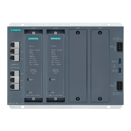
System overview 3.3 Basic components of the system ① RJ45 Ethernet port (with display LEDs) ② Slots for CPU modules ③ Slots for communications modules. These are equipped with a protective cover for unused slots. ④ USB port ⑤ Power supply connection 24 V DC ⑥... - Page 14 System overview 3.3 Basic components of the system Design of the front and bottom panel The following figure shows the front panel and bottom of the CPU module: ① Fixing screw ② Reset button ③ Status LEDs ④ Micro HDMI port ⑤...
- Page 15 System overview 3.3 Basic components of the system Design of the side The following figure shows the left side of the CPU module: ① Fixing screw ② Nameplate (Page 22) CN 4100 Communication System Equipment Manual, 10/2021, A5E50871363-AA...
- Page 16 System overview 3.3 Basic components of the system CN 4100 Communication System Equipment Manual, 10/2021, A5E50871363-AA...
-
Page 17: Plant Engineering
Plant engineering The position of the SIMATIC CN 4100 communication system in the topology and typical applications are shown in the figure below: Note Network security To secure the communications of the plant network, you should use a SCALANCE firewall. - Page 18 • When a single CPU module is used, it must be plugged into the left CPU module slot. Configuration example The following figure shows an example of the configuration of the SIMATIC CN 4100 communication system. Included are: • A redundant connection to the plant network.
- Page 19 Plant engineering 4.1 SIMATIC CN 4100 communication system configuration The possible configurations are listed below. Each table row corresponds to one configuration. Redun‐ Slots for CPU Slots for communi‐ Integrated connections dancy cations modules CPU 1 CPU 2 CM 1 CM 2 X1.1...
- Page 20 Plant engineering 4.1 SIMATIC CN 4100 communication system configuration CN 4100 Communication System Equipment Manual, 10/2021, A5E50871363-AA...
-
Page 21: Installation
Note that there must be enough space for mounting and heat dissipation of the modules. If you need to protect SIMATIC CN 4100 from access, install the system in a control cabinet. Minimum clearances in the control cabinet (Page 23) -
Page 22: Information On The Nameplate
Only the information printed on the nameplate of the respective component is valid. Approvals and certifications (Page 59) The approvals and certifications shown below are examples only. This section describes the information on the nameplates of the SIMATIC CN 4100 communication system components. Design of the nameplate The identification data on the nameplate is more extensive depending on the component. -
Page 23: Basics For Mounting
Minimum clearances in the control cabinet Definition The installation depth of the SIMATIC CN 4100 is 162 mm. It is based on the components being plugged into each other (rack, CPU module and communications modules). There should be at least 100 mm of space in front of the module front panel. -
Page 24: Dimensions For The Drill Hole
Installation 5.4 Basics for mounting 5.4.2 Dimensions for the drill hole Definition The dimensions for the holes depend on the rack. The rack has four holes for fixing screws. Description All drill holes are equidistant from the edges. The following dimensions for the holes are available: CN 4100 Communication System Equipment Manual, 10/2021, A5E50871363-AA... -
Page 25: Notes On Protective Grounding
Installation 5.4 Basics for mounting 301 mm Outer dimensions of the rack 226 mm 38 mm Horizontal distance from the edge to the center of the hole 225 mm Horizontal distance between the centers of the holes 5 mm Vertical distance from the edge to the center of the hole 216 mm Vertical distance between the centers of the holes 5.4.3... -
Page 26: Grounding
Installation 5.4 Basics for mounting Grounding via reference potential The reference potential of the SIMATIC CN 4100 communication system can be connected to ground. A grounding screw is used for this. Notes on the reference potential (Page 27) Application (providing floating reference potential): •... -
Page 27: Notes On The Reference Potential
5.4.4.2 Notes on the reference potential If the SIMATIC CN 4100 communication system has been configured with grounded reference potential, any interference currents that occur are diverted to the protective conductor/local ground. A grounding screw contact is used for this. -
Page 28: Overview Of The Installation
• No line for potential equalization can be laid. • Analog signals (some mA or μA) are transmitted. • Foil shields (static shields) are used. Configuration The following figure shows the configuration of the SIMATIC CN 4100 rack with grounded cable shields. ① Grounding screw in grounded state ②... - Page 29 Mounting a rack When installing the SIMATIC CN 4100 communication system, start with the rack. SIMATIC CN 4100 modules are "open equipment" according to IEC 61131-2 and an "open type" according to UL/CSA approval. The following alternative installation methods are prescribed to...
-
Page 30: Installation
Installation 5.6 Installation Applications • Mounting a rack (Page 31) • Grounding the rack with a cable (Page 32) Plugging in the modules Plug the modules into the slots of the rack. Start from the left with the CPU modules. If a slot is not equipped with a module, plug a slot cover onto the slot. -
Page 31: Mounting A Rack
Installation 5.6 Installation ① Grounding screw in grounded state ② Metal enclosure of the rack (grounded) ③ Power supply connection ④ Ground potential of the internal circuit Result The reference potential of the rack is floating. 5.6.2 Mounting a rack Requirement •... -
Page 32: Grounding The Rack With A Cable
Installation 5.6 Installation Note Before installing controllers with floating reference potential, make the relevant settings on the rack. Result The rack is mounted and screwed to the base. 5.6.3 Grounding the rack with a cable Requirement • The basics for protective grounding are known. •... -
Page 33: Plugging In The Module
Installation 5.6 Installation ① Rack ② Contact washer ③ Fastening nut ④ Washer ⑤ Cable lug ⑥ Cable ⑦ Fixing bolt ⑧ Mounting level Result The rack is grounded via a cable. 5.6.4 Plugging in the module Requirement • The rack is mounted. •... -
Page 34: Grounding The Module With A Cable
Installation 5.6 Installation 5.6.5 Grounding the module with a cable Requirement • The basics for protective grounding are known. • The Module is mounted and screwed to the base. • The cable for grounding has a cross-section >=1.0 mm². • Required tools: –... -
Page 35: Connecting
Connecting Notes on operation Using the SIMATIC CN 4100 communication system in a plant requires that special rules and regulations be observed, depending on the area of application. This section provides an overview of the most important rules that you need to observe when using the SIMATIC CN 4100 communication system. -
Page 36: Notes On Wiring
Protection against external electrical influences Observe the following for protection against electrical influences or faults: • For all plants with SIMATIC CN 4100, ensure that the plant is connected to a protective conductor with sufficient cross-section to dissipate electromagnetic interference. - Page 37 80 °C. Note Reverse polarity protection The input power module of the SIMATIC CN 4100 system is protected against reverse polarity of the input voltage. TWIN end sleeves for the push-in terminal leads Due to the space required by TWIN end sleeves with a cross-section of 0.75 mm...
-
Page 38: Overview Of Rack Wiring
Note the technical specifications and the information on the supply voltage in the section "Notes on operation (Page 35)". Terminals for power supply Observe the wiring rules for the SIMATIC CN 4100 communication system. Notes on wiring (Page 36) Connecting or disconnecting the power supply... -
Page 39: Supply Of The Rack
Connecting 6.4 Supply of the rack Supply of the rack 6.4.1 Connections of the rack The rack has the following connections: ① RJ45 Ethernet port ② X1.1 ③ X1.2 ④ X2.2 ⑤ X2.1 ⑥ ⑦ Power supply connection ⑧ EXT2 USB 3.0 port ⑨... - Page 40 Connecting 6.4 Supply of the rack Ext1 USB 3.0 port Ext2 Internal wiring: Power supply The wiring is shown in the following figure: CN 4100 Communication System Equipment Manual, 10/2021, A5E50871363-AA...
- Page 41 Connecting 6.4 Supply of the rack Internal wiring: Bus connections The wiring is shown in the following figure: CN 4100 Communication System Equipment Manual, 10/2021, A5E50871363-AA...
- Page 42 Connecting 6.4 Supply of the rack Internal wiring: USB ports The wiring is shown in the following figure: CN 4100 Communication System Equipment Manual, 10/2021, A5E50871363-AA...
-
Page 43: Supply Voltage
The wiring is shown in the following figure: 6.4.3 Supply voltage Definition The supply voltage is used to operate the SIMATIC CN 4100 communication system. You connect the supply voltage to the rack. Description The following figure shows a connection for the supply voltage: ①... -
Page 44: Connecting The Supply Voltage To The Rack
Connecting 6.4 Supply of the rack ③ Spring release ④ Push-in terminal 6.4.4 Connecting the supply voltage to the rack Requirement • The supply voltage is switched off. • The respective conductor is connected. • Required tools: – Cable stripper Procedure 1. -
Page 45: Commissioning
After the first power-on, the operating system installs itself. In addition, the operating system prepares the services so that an initial setup can be performed. The entire process takes about 8 minutes. After the setup phase, the SIMATIC CN 4100 can be configured for use in the plant. Description of the commissioning Commissioning has to be done for all CPU modules. -
Page 46: Phases
After a successful setup phase, the SIMATIC CN 4100 communication system is ready for configuration. For this, the SIMATIC CN 4100 can be reached via its MAC address in the network. A network connection must be established to configure the SIMATIC CN 4100. -
Page 47: Status Of The Leds During Firmware Installation
Commissioning 7.2 Phases LEDs After 1s After 2s After 3s After 4s After 5s RL failure COMM failure BIOS update step 2 - LED status for successful installation LEDs After 1s After 2s After 3s After 4s After 5s STOP Master Standby AH failure... -
Page 48: Status Of The Leds During System Configuration
Commissioning 7.2 Phases LED status for error LEDs After 1s After 2s After 3s After 4s After 5s STOP Master Standby AH failure RL failure COMM failure 7.2.3 Status of the LEDs during system configuration Note the LED status during configuration. The following tables show the lighting of the respective LED at the respective time (in seconds). - Page 49 Commissioning 7.2 Phases LED status for error LEDs After 1s After 2s After 3s After 4s After 5s STOP Master Standby AH failure RL failure COMM failure CN 4100 Communication System Equipment Manual, 10/2021, A5E50871363-AA...
- Page 50 Commissioning 7.2 Phases CN 4100 Communication System Equipment Manual, 10/2021, A5E50871363-AA...
-
Page 51: Operation
Operation Operating the CPU module 8.1.1 Notes on the reset button Definition The reset button of the CPU module has the following functions: • Switching on: Switching on the CPU module (Page 52) • Restart: Restarting the CPU module (Page 52) •... -
Page 52: Using The Reset Button
Operation 8.1 Operating the CPU module 8.1.2 Using the reset button 8.1.2.1 Switching on the CPU module Requirement • You have adhered to the basics for mounting. • The supply voltage is connected to the rack. • For power-on again: The CPU has been switched off before via the reset button. Procedure for commissioning after connection Switch on the supply voltage. -
Page 53: Switching Off The Cpu Module
Operation 8.1 Operating the CPU module 8.1.2.3 Switching off the CPU module Requirement • You have adhered to the basics for mounting. • The supply voltage is connected to the rack. • The CPU module has been started. Procedure Press and hold the reset button for 6 seconds. Result The system powers down together with the CPU module. -
Page 54: Analyzing The Communications Modules
Operation 8.2 Analyzing the communications modules Master module Standby module Continuous light Flashes Continuous light Flashes RL failure Failure of redundancy Failure of redundancy Failure of redundancy Failure of redundancy connection (both) connection (single) connection (both) connection (single) COMM error Error com plugin to Error com plugin to field devices;... -
Page 55: Leds Of The Rj45 Port
Operation 8.3 LEDs of the RJ45 port LEDs of the RJ45 port Definition Each RJ45 port has two LEDs to indicate the status of its Ethernet connection. RJ45 Ethernet ports are available on the following devices: • Rack Description ① LED is off: 10 Mbps Green steady light: 100 Mbps Orange steady light: 1000 Mbps... - Page 56 Operation 8.3 LEDs of the RJ45 port CN 4100 Communication System Equipment Manual, 10/2021, A5E50871363-AA...
-
Page 57: Maintenance And Servicing
Maintenance and servicing Notes on maintenance When a SIMATIC CN 4100 communication system is configured redundantly, its modules may be replaced online. Applications • Replacing the module (Page 57) Maintenance 9.2.1 Replacing the module Requirement • The rack is mounted. - Page 58 Maintenance and servicing 9.2 Maintenance Result The module has been replaced. CN 4100 Communication System Equipment Manual, 10/2021, A5E50871363-AA...
-
Page 59: Technical Specifications
• The standards and test values that the SIMATIC CN 4100 communication system complies with and fulfills. • The test criteria according to which the SIMATIC CN 4100 communication system was tested. Validity of the information on the components NOTICE... -
Page 60: Ce Marking
2014/35/EU "Electrical equipment designed for use within certain voltage limits" (Low Voltage Directive) According to the requirements of EN 61010-2-201, the components of the SIMATIC CN 4100 communication system that fall under the Low Voltage Directive have been tested. EMC Directive 2014/30/EU "Electromagnetic Compatibility"... -
Page 61: Ukca Marking
Technical specifications 10.1 Standards and approvals General industry standards The SIMATIC CN 4100 communication system is designed to meet or exceed most general industry standards. These are in particular: • Power input on shielded and unshielded signal lines: IEC 61000-4-6 (Ed. 4.0 2013-10 + corr. 1:2015); EN 61000-4-6 (2014-02); DIN EN 61000-4-6 (2014-08) •... - Page 62 Technical specifications 10.1 Standards and approvals Underwriters Laboratories Inc. meet the following standards: • UL 508 (Industrial Control Equipment) • CSA C22.2 No. 142 (Process Control Equipment) CN 4100 Communication System Equipment Manual, 10/2021, A5E50871363-AA...
-
Page 63: Technical Specifications Of Components
Technical specifications 10.2 Technical specifications of components 10.2 Technical specifications of components 10.2.1 Technical specifications - CPU module Technical specifications TED Article number 6DL4178-0BH01-0XX0 General information Product type designation CPU modules 1 slot HW functional status FS02 Firmware version V1.0 Engineering with V9.0 SP3 •... - Page 64 Technical specifications 10.2 Technical specifications of components Article number 6DL4178-0BH01-0XX0 • Runtime license required • OPC UA Client – Security policies Yes; "anonymous" or by user name & password – User authentication – Number of connections, max. 2 500 – Number of nodes of the client interfaces, max.
- Page 65 Technical specifications 10.2 Technical specifications of components Ambient conditions, tested according to IEC 61131-2 Ambient temperature for storage/transport, tested according to IEC 60068-2 • Min. • -40 °C • Max. • 85 °C Humidity without condensation during operation • Min. •...
-
Page 66: Technical Specifications - Rack
Technical specifications 10.2 Technical specifications of components 10.2.2 Technical specifications - rack Technical specifications TED Article number 6DL4170-1RB01-2XX0 General information Product type designation rack Hardware configuration Slots • Number of slots – of which for CPU, max. Interfaces Number of industrial Ethernet interfaces Number of USB interfaces Protocols Supports protocol for PROFINET IO... -
Page 67: Dimension Drawing
Dimension drawing Dimensions of the rack The following figures show the dimensions of the rack with four plugged-in modules (two CPU modules and two different communications modules). Rack from the front CN 4100 Communication System Equipment Manual, 10/2021, A5E50871363-AA... - Page 68 Dimension drawing A.1 Dimensions of the rack Rack from below CN 4100 Communication System Equipment Manual, 10/2021, A5E50871363-AA...
-
Page 69: Data Connections
Data connections Connections of the rack B.1.1 USB 3.0 ports of the rack Definition The USB 3.0 port is required for the setup and maintenance of the communication system. Description The rack is equipped with two USB 3.0 ports. Design Description USB_P5V_fused (O) USB_D0M (I/O) -
Page 70: Connections Of The Cpu Module
Data connections B.2 Connections of the CPU module Description The rack is equipped with the following Ethernet ports (10/100/1000 Mbps) for communication via fieldbus protocol or standard Ethernet: • Two Ethernet ports for the plant network • Four Ethernet ports for third-party systems Design Description BI_DA+... -
Page 71: Micro-Hdmi Port Of The Cpu Module
Data connections B.2 Connections of the CPU module Design Description TMDS Data2+ TMDS Data2 shield TMDS Data2− TMDS Data1+ TMDS Data1 shield TMDS Data1− TMDS Data0+ TMDS Data0 shield TMDS Data0− TMDS Clock+ TMDS Clock shield TMDS Clock− Reserved (HDMI 1.0-1.3c), Utility/HEC/ARC (Optional, HDMI 1.4+ with HDMI Ethernet channel and audio return channel) SCL (Line I²C "Serial Clock"... - Page 72 Data connections B.2 Connections of the CPU module Design Description USB_P5V_fused (O) USB_D0M (I/O) USB_D0P (I/O) Not connected USB_GND CN 4100 Communication System Equipment Manual, 10/2021, A5E50871363-AA...
- Page 73 Service & Support Service & Support Attach / detach components The components are maintenance-free. Repairs to the components of the communication system itself may only be carried out by the manufacturer. Warranty The warranty is subject to compliance with the safety and commissioning instructions. CN 4100 Communication System Equipment Manual, 10/2021, A5E50871363-AA...
- Page 74 Our Service & Support accompanies you worldwide in all matters related to Automation and Drives from Siemens. In more than 100 countries, directly on site and throughout all phases of the life cycle of your machines and plants.
- Page 75 Service & Support C.1 Service & Support Field service With Field Service, we offer services covering all aspects of commissioning and maintenance – so that the availability of your machines and systems is guaranteed in every situation. Spare parts Plants and systems in all industries worldwide must operate with more and more availability. We support you in preventing downtime from the outset: With a worldwide network and optimal logistics chains.
- Page 76 • You can find information about the technical support available in the appendix of this documentation. • The technical documentation for the individual SIMATIC products and systems is available on the Internet (https://www.siemens.com/simatic-tech-doku-portal). • You can find the online catalog and online ordering system on the Internet (https:// mall.industry.siemens.com).