Advertisement
Quick Links
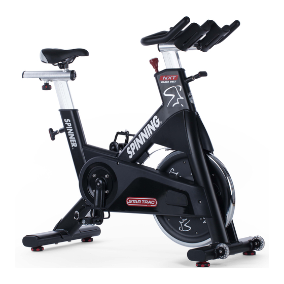
Star Trac Spinner
A
ssembly &
Use the following procedures to unpack and assemble your Star Trac SPINNER
UNPACKING
AND
Position the shipping carton so the "Heavy End" logo is located at the bottom. Open the top of the carton and fold back all four flaps.
Carefully tilt the box forward so that the box may be lifted to expose the bike. Remove all parts from the shipping carton and foam
inserts, and verify that the following parts are included in your shipment:
NOTE: All tools required to assemble the bike are included within the packaging, except for a Rubber Mallet, which is recommended
when assembling the pedals onto the bike.
NXT Black Belt Parts List
Description
Main Frame Assembly
Handlebar Post
Handlebar w/ Grip & Water Bottle Holders
Seat Post
Seat Slider Assembly w/ Saddle
Front Leg Assembly w/ Transport Wheels
Rear Leg Assembly
Pedals (set of two)
Spare Parts Kit - Save the box of spare parts in a safe place so you have service parts when needed in the future.
Take time now to enter your Spinner NXT Black Belt serial number in the space below (serial number is located on underside the
bottom rear cross member).
If parts are missing, or if you have any operational questions, please call Star Trac's Service department at (800) 503-1221.
Have your serial number ready.
Serial No.
NOTE: If you are missing any of the parts listed above, inspect the packing material and the box for items that may have been
overlooked.
If parts are missing, or if you have any product questions, please call Star Trac's Service Department at (800) 503-1221, please have
your bike's serial number ready.
CAUTION:
Damage to the bike during assembly is not covered as part of the limited Star Trac warranty. Take care not to drop or lean
the bike on the handle bar pop-pin. Carefully stand the bike up in the normal upright position on a stable surface so it will not tip over
during assembly.
NXT Black Belt Installation
©
S
etup
PARTS LIST
Qty.
1
1
1
1
1
1
1
1
Assembly & Setup
®
NXT Black Belt™
Description
M8x1.25x14 Specialty Hex Bolt
M8x1.25, 30mm Hex Head Bolt
8mm Split Lock Washer
8mm Plain Washer
Wrench Hex, 4mm
Wrench Hex, 8mm
Multi-Wrench
Spare Parts Kit (includes brake pad and pedal
straps)
.
Qty.
2
4
4
4
1
1
1
1
Advertisement

Related Manuals for Star Trac Spinner NXT Black Belt


Summary of Contents for Star Trac Spinner NXT Black Belt
- Page 1 Spare Parts Kit - Save the box of spare parts in a safe place so you have service parts when needed in the future. Take time now to enter your Spinner NXT Black Belt serial number in the space below (serial number is located on underside the bottom rear cross member).
-
Page 2: Assembly And Setup
Assembly & Setup SSEMBLY NSTRUCTIONS Unboxing the unit requires turning the sealed box upside down to open the bottom flaps (Fig. 1). Fig. 1 Return the opened box back to the upright position (Fig. 2). Fig. 2 Expose the packaged bike by pulling the box up (Fig.3). Fig. - Page 3 Assembly & Setup Remove the following: handle bar & its packaging (Fig. 4) from the center packed location. Fig 4 Remove the: hardware pack, seat, handle bar post, and seat post from the foam covering the front section of the Spinner frame (Fig.
- Page 4 Assembly & Setup Remove the foam packaging from the rear section of the Spinner frame (Fig. 7). Fig. 7 Locate the rear foot assembly along with the corresponding hardware that secures it to the Spinner frame (Fig. 8). Hardware: Qty: M8x1.25x30mm Hex Head Bolt 8mm Split Lock Washer 8mm Plain Washer...
- Page 5 Assembly & Setup 10. Stand the Spinner frame on the opposite end and place a piece of foam or rag under the seat post frame section (Fig. 10). Fig. 10 11. Split and remove (Fig. 11) the foam covering the front of the Spinner frame.
- Page 6 Assembly & Setup 13. Install the front foot assembly (Fig. 13) and tighten the hardware using the supplied multi sized open wrench. Note: These bolts must be torque between 35-40 Lb-Ft (47-54 Nm). Fig. 13 14. Return the bike to the upright position (Fig.14). Fig.
- Page 7 Assembly & Setup 16. Locate and install the seat height adjustment pop pin onto the Spinner frame (Fig. 16) using the supplied multi size open wrench. Fig. 16 17. Locate and mount the seat slider assembly onto the seat post by relieving spring tension on the large knob and pulling the small thumb pin located on the underside of the seat post slider (Fig.
- Page 8 Assembly & Setup 19. Locate the handle bar assembly and remove the button head stop bolt that is pre-inserted into the slider section (Fig. 19). Fig. 19 20. Mount the handle bar to the front height adjustment post (Fig. 20) by reliving spring tension on the large knob and sliding the handle bar into place.
- Page 9 Assembly & Setup 22. Locate the set of pedals along with the corresponding hardware (Fig. 22). Hardware: M8x1.25x14mm Specialty Hex Bolt Fig. 22 23. Insert each pedal into its corresponding crank arm (Fig. 23). Note: For correct orientation, verify the foot cage is facing upwards on each pedal when inserting into the crank arm.
- Page 10 Assembly & Setup 25. Install the pedal securing bolts (Fig. 25) into each pedal thru the back of each crank arm using an 8mm hex key. Note: These bolts must be torqued between 33-37 Lb-Ft (45-50 Nm). Fig. 25...
-
Page 11: T Esting B Ike
Assembly & Setup esting Use this checklist to perform the bike test procedure. Recheck all the bolts and make sure they are all tightened to the proper torque specification (when indicated) and no parts are missing. Test the handlebar and seat post to make sure they move freely and you are able to lock in at different positions.