Sign In
Upload
Manuals
Brands
Bard Manuals
Air Conditioner
FUSION-TEC WR58BPB
Bard FUSION-TEC WR58BPB Manuals
Manuals and User Guides for Bard FUSION-TEC WR58BPB. We have
2
Bard FUSION-TEC WR58BPB manuals available for free PDF download: Service Instructions Manual
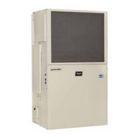
Bard FUSION-TEC WR58BPB Service Instructions Manual (54 pages)
WALL-MOUNT AIR CONDITIONER
Brand:
Bard
| Category:
Air Conditioner
| Size: 1.36 MB
Table of Contents
Table of Contents
2
Air Conditioner
1
General Information
4
Using the TEC-EYE TM
6
FIGURES and TABLES Figure 1 TEC-EYE Display and Interface
6
Figure 2 TEC-EYE Connection to Unit Control
6
Main Status Screen
7
TEC-EYE Acronyms
7
TEC-EYE Screen Structure and Password Level
7
Figure 3 Quick Menu Icons
8
Figure 4 Cool and Heat Setpoints
8
Figure 5 Orphan Mode Staging
8
Figure 6 Master Staging
8
Information
8
Master Staging
8
Orphan Mode Staging
8
Quick Menu
8
Setpoints
8
Staging Information
8
A/C Circuit Measurements
9
Alarm Log
9
Component Lifetime Hours
9
Figure 7 A/C Circuit Measurements
9
Figure 8 Last 24 Operation
9
Figure 9 Software Version
9
Last 24 Hour Operation
9
Software Version
9
Addressing Wall-Mount Units
10
Executing a Run Test
10
Figure 10 Changing Unit Address
10
Figure 11 Executing Run Test
10
Figure 12 Run Test Summary
10
Press ENTER Key to Save
10
Figure 13 Run Test: Motors & Sensors
11
Figure 14 Run Test: A/C Circuit
11
Figure 15 Restoring Factory Default Settings
11
Reset to Factory Defaults
11
Run Test Parameter Descriptions
11
TEC-EYE Hand-Held Diagnostic Tool
6
Alarm Adjustment
12
Acknowledging Alarms
12
Clearing Alarm Logs and Counters
12
Clearing Alarms
12
Exporting Alarm Logs
12
Figure 16 Clearing All Alarms
12
Figure 17 Clearing Alarm Logs and Counters
12
Exporting 7 Day Logs
13
Operation
12
Unit On/Off
12
Orphan Model
13
Temperature/Humidity Control
13
Figure 18 Changing Zone
13
Figure 19 Adjusting Return Air Sensor
13
Return Air Temperature Sensor
13
Temperature/Humidity Control Components
13
Cooling Sequence: Economizer Available
14
Economizer Operation in Orphan Mode
14
Figure 20 Staging
14
Return Air Temperature Alarm
14
Temperature/Humidity Control Operation
14
Adjusting Cooling Staging
15
Cooling Sequence: Economizer Not Available
15
Figure 21 Enabling Free Cooling Delay
15
Figure 22 Viewing Unit Stages
15
Heating Sequence
15
Staging
15
Adjusting Heating Staging
16
Dehumidification
16
Zone
13
Electronic Expansion Valve (EEV)
16
EEV Components
16
EEV Instructions for Vacuum, Reclaim, Charge Unit
16
Electronic Expansion Valve
16
Figure 23 Adjusting Cooling Stage Differentials
16
Figure 24 Adjusting Heating Stage Differentials
16
Figure 25 Overriding EEV Output
17
Figure 26 Electronic Expansion Valve and Service Tool
17
Suction Pressure Transducer
17
System Pressures
17
Evaporator Freeze Condition Alarm
18
Figure 28 Voltage/Pressure: Suction Pressure Transducer
18
Figure 30 Adjusting Freeze Setpoint and Alarm Delay
18
Suction Pressure Alarm
18
Suction Temperature Alarm
18
Suction Temperature Sensor
18
Troubleshooting the Suction Pressure Transducer
18
Additional EEV Alarms
19
EEV Operation
19
EEV Superheat Control
19
Low Superheat Alarm
19
Indoor Airflow
19
Blower
19
Figure 31 Putting Blower Output into Override Mode
19
Indoor Airflow Components
19
Blower Status Switch/Output Volts
20
Controller CFM
20
Blower Status Switch
20
Dehumidification
20
Blower Status Alarm
21
Figure 32 Dirty Filter Switch/Blower Status Switch
21
Figure 33 Verifying Differential Airflow Status
21
Figure 34 Adjusting Air Flow Alarm Delay
21
Output Volts
20
Table 8
21
Heating
20
Mode
20
Wr36Bp* 0.00 1260 1200 995
21
Wr36Bp* 1200
21
Wr58Bp
21
Dirty Filter Switch
22
Dirty Filter Alarm
22
Figure 35 Dirty Filter Switch and Filter Indicator Light
22
Filter Indicator Light
22
Filters
22
Additional Indoor Airflow Alarms
23
Supply Air Temperature Alarm
23
Condenser Fan
23
Condenser Fan Components
23
Figure 36 Enabling High Sensible Mode
23
Figure 37 Verifying Condenser Fan Output
23
Press MENU Key to Go to the Main Menu Screen
23
Figure 38 Fan Blade Setting
24
Figure 39 Adjusting Liquid Pressure Transducer Values
24
Figure 40 Voltage/Pressure: Liquid Pressure Transducer
24
Liquid Line Pressure Transducer
24
Liquid Pressure Transducer Alarm
24
Liquid Temperature Sensor
24
Troubleshooting the Liquid Pressure Transducer
24
Condenser Fan Operation
25
Condenser Fan Speed
25
Condenser Fan Speed Control
25
Figure 41 Adjusting Liquid Temperature Values
25
Figure 42 Liquid Pressure Control Setpoint
25
High Pressure Control
25
Additional Condenser Fan Alarms
26
Dirty Condenser Coil Alarm
26
Low Ambient Control
26
Second Stage Drop out
26
Indoor Airflow Operation
23
Blower Speed Control
23
High Sensible Mode
23
Compressor
26
Compressor Components
26
Compressor Control Module (CCM)
26
Delay-On-Make Timer
26
High Pressure Detection
26
Short Cycle Protection/Delay-On-Break
26
Brownout Protection W/Adjustment
27
Figure 43 8201-164 Compressor Control Module
27
Compressor Low Temperature Limit
28
Compressor Operation
28
Figure 44 Adjusting Compressor Delays
28
High Pressure Safety Switch
28
Phase Monitor
28
Refrigerant High Pressure Alarm
28
Additional Compressor Alarms
29
Refrigerant Low Pressure Alarm
29
Economizer
29
Actuator
29
Economizer Components
29
Figure 45 Adjusting Compressor Low Temp Limit
29
Figure 46 Adjusting Low Pressure Alarm Settings
29
Figure 47 Damper Output and Override
29
Dust Sensor
30
Dust Sensor Failure Alarm
30
Figure 48 Dust Sensor
30
Figure 49 Adjusting Dust Sensor Alarm Setpoint
30
High Dust Limit Alarm
30
Damper Blade
31
Damper Failed to Open Alarm
31
Damper Switch
31
Figure 50 Adjusting Minimum Damper Position
31
Figure 51 Damper Switch
31
Minimum Damper Position
31
Press up or down Keys to Scroll to Digital in Config C1
31
Damper Failed to Close Alarm
32
Figure 52 Adjusting Damper Alarm Delay
32
Figure 53 Outdoor Air Sensor
32
Figure 54 Outdoor Humidity Sensor
32
Outdoor Humidity Sensor Failure Alarm
33
Outdoor Temperature Sensor Failure Alarm
33
Outdoor Temperature and Humidity Combination Sensor
32
Supply Temperature Sensor
33
Figure 55 Supply Air Sensor
33
High Supply Air Temperature Alarm
33
Low Supply Air Temperature Alarm
33
Supply Temperature Sensor Failure Alarm
33
Economizer Operation
34
Figure 57 Economizer Setup A2
34
Emergency Cooling Mode
35
Emergency Ventilation Mode
35
Figure 58 Economizer Setup A3
35
Model/Serial Number Configuration
35
Bard Guard Anti-Theft System Option
36
Electric Heat Option
36
Electric Heat Components
36
Electric Heat Operation
36
Electric Heating Element
36
Thermal Overload
36
Inverter Option
36
Smoke Detector Unit Disable Option
36
Figure 59 FUSION-TEC WR Series Nomenclature
37
Figure 60 FUSION-TEC WR Series Unit Control Board
38
General
40
Important Installer Note
40
R410-A Refrigerant Charge
40
Refrigerant Information
40
Safety Practices
40
Topping off System Charge
40
Pressure Service Ports
41
Bard Guard Anti-Theft System Option
42
Maintenance
42
Standard Maintenance Procedures
42
8301-067 Outdoor Temperature/Humidity Sensor
43
8301-067 Sensor Connections
43
Figure 61 8301-067 Sensor Electrical Connections
43
Figure 62 8301-067 Sensor Terminal Connections
43
8301-067 Humidity Sensor Calibration
46
8301-067 Humidity Sensor Test Value Outputs
46
Figure 63 8301-067 DIP Switch/Output Configuration
46
Troubleshooting
43
8301-057 Blower Status Switch/Dirty Filter Switch
47
Figure 64 8301-057 Air Differential Switch Terminals
47
8612-061 Dust (Particulate) Sensor Control Board
48
8612-061 Control Board Output Signal Not Responsive to Dust
48
Figure 65 8612-061 Dust Sensor Alarm Board
48
Figure 66 Dust Sensor Alarm Board Power Supply Check
49
8301-073 Dust (Particulate) Sensor
50
8408-044 Return Air Sensor/Suction Sensor
51
8301-066 Supply Air Sensor
52
8406-157 Liquid Line Pressure Transducer
53
8406-158 Suction Pressure Transducer
54
Advertisement
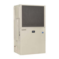
Bard FUSION-TEC WR58BPB Service Instructions Manual (56 pages)
Wall-Mount
Brand:
Bard
| Category:
Air Conditioner
| Size: 2.06 MB
Table of Contents
Table of Contents
2
Using the TEC-EYE
6
Figure 2 TEC-EYE Connection to Unit Control
6
TEC-EYE Screen Structure and Password Level
7
TEC-EYE Acronyms
7
Main Status Screen
7
Quick Menu
8
Figure 3 Quick Menu Icons
8
Figure 4 Cool and Heat Setpoints
8
Figure 5 Orphan Mode Staging
8
Figure 6 Master Staging
8
Information
8
Master Staging
8
Orphan Mode Staging
8
Setpoints
8
Staging Information
8
A/C Circuit Measurements
9
Component Lifetime Hours
9
Figure 7 A/C Circuit Measurements
9
Figure 8 Last 24 Operation
9
Figure 9 Software Version
9
Last 24 Hour Operation
9
Software Version
9
Software Versioning Guide
9
Alarm Log
10
Addressing Wall-Mount Units
10
Executing a Run Test
10
Figure 10 Changing Unit Address
10
Figure 11 Executing Run Test
10
Figure 12 Run Test Summary
10
Run Test Parameter Descriptions
11
Reset to Factory Defaults
11
Figure 13 Run Test: Motors & Sensors
11
Figure 14 Run Test: A/C Circuit
11
Figure 15 Restoring Factory Default Settings
11
Figures and Tables Figure 1 TEC-EYE Display and Interface
6
TEC-EYE Hand-Held Diagnostic Tool
6
Using the TEC-EYE TM
6
Alarm Adjustment
12
Acknowledging Alarms
12
Clearing Alarms
12
Clearing Alarm Logs and Counters
12
Exporting Alarm Logs
12
Figure 16 Clearing All Alarms
12
Figure 17 Clearing Alarm Logs and Counters
12
Exporting 7 Day Logs
13
Operation
12
Unit On/Off
12
Orphan Model
13
Temperature/Humidity Control
13
Temperature/Humidity Control Components
13
Figure 18 Changing Zone
13
Figure 19 Adjusting Return Air Sensor
13
Return Air Temperature Sensor
13
Return Air Temperature Alarm
14
Temperature/Humidity Control Operation
14
Cooling Sequence: Economizer Available
14
Economizer Operation in Orphan Mode
14
Figure 20 Staging
14
Adjusting Cooling Staging
15
Cooling Sequence: Economizer Not Available
15
Figure 21 Enabling Free Cooling Delay
15
Figure 22 Viewing Unit Stages
15
Heating Sequence
15
Staging
15
Adjusting Heating Staging
16
Dehumidification
16
Dehumidification Modes
16
Figure 23 Adjusting Cooling Stage Differentials
16
Figure 24 Adjusting Heating Stage Differentials
16
Cycling Dehumidification Operation
17
Zone
13
Electronic Expansion Valve (EEV)
17
EEV Components
17
EEV Instructions for Vacuum, Reclaim, Charge Unit
17
Electronic Expansion Valve
17
Figure 25 Overriding EEV Output
18
Figure 26 Electronic Expansion Valve and Service Tool
18
Suction Pressure Transducer
18
System Pressures
18
Evaporator Freeze Condition Alarm
19
Figure 28 Voltage/Pressure: Suction Pressure Transducer
19
Suction Pressure Alarm
19
Suction Temperature Alarm
19
Suction Temperature Sensor
19
Troubleshooting the Suction Pressure Transducer
19
EEV Operation
20
EEV Superheat Control
20
Additional EEV Alarms
20
Low Superheat Alarm
20
Indoor Airflow
20
Indoor Airflow Components
20
Blower
20
Figure 30 Adjusting Freeze Setpoint and Alarm Delay
20
Figure 31 Putting Blower Output into Override Mode
20
Blower Status Alarm
22
Blower Status Switch
22
Dirty Filter Switch
22
Figure 32 Dirty Filter Switch/Blower Status Switch
22
Figure 33 Verifying Differential Airflow Status
22
Figure 34 Adjusting Air Flow Alarm Delay
22
Filters
22
Dirty Filter Alarm
23
Filter Indicator Light
23
Indoor Airflow Operation
23
Figure 35 Enabling High Sensible Mode
23
High Sensible Mode
23
Blower Speed Control
24
Additional Indoor Airflow Alarms
24
Supply Air Temperature Alarm
24
Condenser Fan
24
Condenser Fan Components
24
Figure 36 Dirty Filter Switch and Filter Indicator Light
24
Figure 37 Verifying Condenser Fan Output
25
Figure 38 Fan Blade Setting
25
Figure 39 Adjusting Liquid Pressure Transducer Values
25
Liquid Line Pressure Transducer
25
Troubleshooting the Liquid Pressure Transducer
25
Liquid Pressure Transducer Alarm
26
Liquid Temperature Sensor
26
Condenser Fan Operation
26
Condenser Fan Speed
26
Condenser Fan Speed Control
26
Figure 40 Voltage/Pressure: Liquid Pressure Transducer
26
Figure 41 Adjusting Liquid Temperature Values
26
High Pressure Control
26
Low Ambient Control
26
Second Stage Drop out
26
Compressor
27
Compressor Components
27
Compressor Control Module (CCM)
27
Delay-On-Make Timer
27
Figure 42 Liquid Pressure Control Setpoint
27
Brownout Protection W/Adjustment
28
Figure 43 8201-169 Compressor Control Module
28
High Pressure Detection
28
Short Cycle Protection/Delay-On-Break
28
Test Mode
28
High Pressure Safety Switch
29
Phase Monitor
29
Refrigerant High Pressure Alarm
29
Compressor Operation
29
Figure 44 Adjusting Compressor Delays
29
Compressor Low Temperature Limit
30
Additional Compressor Alarms
30
Refrigerant Low Pressure Alarm
30
Economizer
30
Economizer Components
30
Actuator
30
Figure 45 Adjusting Compressor Low Temp Limit
30
Figure 46 Adjusting Low Pressure Alarm Settings
30
Dust Sensor
31
Dust Sensor Failure Alarm
31
Figure 47 Damper Output and Override
31
Figure 48 Dust Sensor
31
High Dust Limit Alarm
31
Damper Blade
32
Damper Switch
32
Figure 49 Adjusting Dust Sensor Alarm Setpoint
32
Figure 50 Adjusting Minimum Damper Position
32
Minimum Damper Position
32
Damper Failed to Close Alarm
33
Damper Failed to Open Alarm
33
Figure 51 Damper Switch
33
Figure 52 Adjusting Damper Alarm Delay
33
Outdoor Temperature and Humidity Combination Sensor
33
Figure 53 Outdoor Air Sensor
34
Figure 54 Outdoor Humidity Sensor
34
Figure 55 Supply Air Sensor
34
Outdoor Humidity Sensor Failure Alarm
34
Outdoor Temperature Sensor Failure Alarm
34
Supply Temperature Sensor
34
Supply Temperature Sensor Failure Alarm
34
High Supply Air Temperature Alarm
35
Low Supply Air Temperature Alarm
35
Economizer Operation
35
Figure 56 Adjusting Supply Air Temperature Differential
35
Figure 57 Economizer Setup A2
35
Figure 58 Economizer Setup A3
36
Bard Guard Anti-Theft System Option
37
Electric Heat Option
37
Electric Heat Components
37
Electric Heating Element
37
Thermal Overload
37
Electric Heat Operation
37
Emergency Cooling Mode
37
Emergency Ventilation Mode
37
Model/Serial Number Configuration
37
Inverter Option
38
Unit Disable Option
38
Figure 59 FUSION-TEC WR Series Unit Control Board
39
Figure 60 FUSION-TEC WR Series Nomenclature
41
General
42
Important Installer Note
42
Pressure Service Ports
42
R410-A Refrigerant Charge
42
Refrigerant Information
42
Safety Practices
42
Topping off System Charge
42
Bard Guard Anti-Theft System Option
44
Maintenance
44
Standard Maintenance Procedures
44
8301-067 Outdoor Temperature/Humidity Sensor
45
8301-067 Sensor Connections
45
Figure 61 8301-067 Sensor Electrical Connections
45
Figure 62 8301-067 Sensor Terminal Connections
45
8301-067 Humidity Sensor Test Value Outputs
48
8301-067 Humidity Sensor Calibration
48
Figure 63 8301-067 DIP Switch/Output Configuration
48
Troubleshooting
45
8301-057 Blower Status Switch/Dirty Filter Switch
49
Figure 64 8301-057 Air Differential Switch Terminals
49
8301-073 Dust (Particulate) Sensor
50
8612-061 Dust (Particulate) Sensor Control Board
51
8612-061 Control Board Output Signal Not Responsive to Dust
51
Figure 65 8612-061 Dust Sensor Alarm Board
51
Figure 66 Dust Sensor Alarm Board Power Supply Check
52
8408-044 Return Air Sensor/Suction Sensor
53
8301-066 Supply Air Sensor
54
8406-157 Liquid Line Pressure Transducer
55
8406-158 Suction Pressure Transducer
56
Advertisement
Related Products
Bard FUSION-TEC WR58BPA
Bard FUSION-TEC WR58
Bard FUSION-TEC WR36BPA
Bard FUSION-TEC WR36BPB
Bard FUSION-TEC WR35
Bard FUSION-TEC WR36
Bard FUSION-TEC WR35BPA
Bard FUSION-TEC WR35BPB
Bard W48L13
Bard W48L2-B
Bard Categories
Air Conditioner
Heat Pump
Medical Equipment
Furnace
Controller
More Bard Manuals
Login
Sign In
OR
Sign in with Facebook
Sign in with Google
Upload manual
Upload from disk
Upload from URL