Table of Contents
Advertisement
Quick Links
Advertisement
Table of Contents
Troubleshooting

Related Manuals for Bard MEGA-TEC W120AP


Summary of Contents for Bard MEGA-TEC W120AP
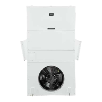
- Page 1 SERVICE INSTRUCTIONS MEGA-TEC WALL-MOUNT AIR CONDITIONER Model W120AP NOTE: LC6000 controller is required for operation when W120AP units are used. Bard Manufacturing Company, Inc. Manual: 2100-671 Bryan, Ohio 43506 Supersedes: www.bardhvac.com Date: 12-17-18 Page 1 of 44...
-
Page 2: Table Of Contents
CONTENTS General Information ...........4 Indoor Airflow .............17 Indoor Airflow Components ......17 Multi-Stage Cooling System ........4 Blower ..........17 Wall-Mount Air Conditioner Units ......4 Blower Status Switch ......18 General ..............4 Blower Status Alarm ......18 Shipping Damage ..........4 Filters ...........18 Additional Publications ..........4 Dirty Filter Switch ........18 Using the TEC-EYE ...........6... - Page 3 Mixed Air Temperature Sensor ....27 Figure 19 Voltage to Pressure: Suction Pressure High Mixed Air Temperature Alarm ..27 Transducer ...........16 Low Mixed Air Temperature Alarm ..28 Figure 20 Adjusting Suction Temperature Sensor Economizer Operation ........28 Values ..........16 Economizer Operation − Figure 21 Adjusting Evaporator Freeze Sensor Minimum Position ........29...
-
Page 4: General Information
Multi-Stage Cooling System Conditioning and Ventilating Systems of Other Than Residence Type, NFPA No. 90A, and Residence Type This Bard cooling system is composed of MEGA-TEC Warm Air Heating and Air Conditioning Systems, NFPA Series wall-mounted air conditioners matched with No. - Page 5 ANSI Z535.5 Definitions: WARNING DANGER: Indicate[s] a hazardous situation which, if not avoided, will result in death or serious injury. The signal word “DANGER” is to be limited to the most Electrical shock hazard. extreme situations. DANGER [signs] should not be used for property damage hazards unless personal injury risk Have a properly trained individual perform appropriate to these levels is also involved.
-
Page 6: Using The Tec-Eye Tm
USING THE TEC-EYE FIGURE 1 TEC-EYE (Bard P/N 8301-059) Display and Interface (Status Screen Shown) UP KEY ALARM KEY MENU KEY ENTER KEY ESCAPE KEY DOWN KEY QUICK MENU ALARM KEY UP KEY Allows viewing of active alarms Steps to next screen in the display menu... -
Page 7: Tec-Eye Menu Structure
TABLE 1 TEC-EYE Menu Structure Unit Status Messages Quick Menu Setpoints Information Message Description Alarm Log Main Menu PLC is on and has not started System Configuration Waiting... running the application yet. Advanced System Configuration I/O Configuration Unit is on and in orphan mode with Digital Inputs Orphan Mode no calls for heating or cooling. -
Page 8: Quick Menu
Quick Menu temperature, liquid line pressure, condensing saturated temperature, suction line temperature, suction line Setpoints pressures, suction saturated temperature, super heat, From this screen, the local unit heating and cooling sub-cooling and electronic expansion valve position. setpoints, used for orphan mode only, can be changed. FIGURE 5 Once the supervisory controller is connected, cooling A/C Circuit Measurements... -
Page 9: Program Version
Current software Use UP or DOWN keys and ENTER key to enter password versions, change log and installation instructions are available on the Bard website at http://www.bardhvac.com/software-download/ The passwords listed above are the default passwords. End users can change these passwords if additional security is desired. -
Page 10: Executing A Run Test
Executing a Run Test Reset to Factory Defaults This unit has the ability to perform a run test that will To reset to factory default settings: operate all available unit functions in order to quickly 1. Press MENU key to go to the Main Menu screen. determine unit operation. -
Page 11: Operation
OPERATION NOTE: Screenshots shown in this manual reflect FIGURE 9 Clearing All Alarms default settings (when applicable). Unit On/Off The wall-mount unit can be turned on and off from the TEC-EYE. Turning the unit off with the following instructions will disable all unit operation. To turn the unit on or off: 1. -
Page 12: Exporting 7 Day Logs
Exporting 7 Day Logs This sensor can be verified and adjusted by: See latest version of Supplemental Instructions manual 1. Press MENU key to go to the Main Menu screen. 7960-826 for information on exporting 7 day I/O logs. 2. Press UP or DOWN keys and ENTER key to enter Exporting Parameters TECHNICIAN password 1313. -
Page 13: Orphan Mode
The unit can be equipped with 0, 1 or 2 stages of other unit still operating. Once the first of the Bard electric heat (see Figure 15 on page 14). wall-mount units is installed and powered on, it will... -
Page 14: Electronic Expansion Valve (Eev)
FIGURE 14 Cooling (without Economizer) Compressor 1 Stage 2 Compressor 2 Compressor 1 Stage 1 75.0°F 75.5°F 76.0°F 76.5°F 77.0°F 77.5°F 78.0°F 78.5°F 79.0°F 79.5°F 80.0°F 80.5°F 81.0°F Cooling Deadband Cooling FIGURE 15 Heating Electric Heater 2 Electric Heater 1 58.0°F 58.5°F 59.0°F... -
Page 15: System Pressures
The valve can also be opened or closed using the EEV used with the suction temperature sensor to provide service tool (Bard Part # 2151-021). This magnetic EEV a real time superheat calculation that determines the service tool (shown in Figure 17) is used to manually EEV position. -
Page 16: Suction Pressure Alarm
FIGURE 19 FIGURE 20 Voltage to Pressure: Suction Pressure Transducer Adjusting Suction Temperature Sensor Values Suction Temperature Alarm Suction Pressure Alarm When the suction temperature sensor value is out of range (-41.0 to 303.0°F), the controller will generate When the suction pressure transducer value is a sensor failure alarm to indicate the sensor is not measured out of range (0-250 PSIG) and the working properly. -
Page 17: Eev Operation
FIGURE 21 5. Press UP or DOWN keys to scroll to Blower 1. Adjusting Evaporator Freeze Sensor Values 6. Press ENTER key to scroll to Blower Overrides? (see Figure 22). 7. Press UP or DOWN key to change No to Go. The override will begin and the screen will change to the override screen (see Figure 22). -
Page 18: Blower Status Switch
TABLE 5 FIGURE 24 Verifying Differential Airflow Status Maximum ESP of Operation Electric Heat Only Model Static Pressure* -B0Z .50" -B09 .50" -B18 .50" -C0Z .50" -C09 .50" -C18 .50" * Unit is rated for free blow non-ducted operation with SG-10W Supply Grille and RG-10W Return Grille. -
Page 19: Filter Indicator Light
FIGURE 25 Dirty Filter Switch and Filter Indicator Light ADJUSTMENT INDICATOR ARROW ADJUSTMENT KNOB FILTER LIGHT SCREW TO REMOVE COVER COVER TUBE LOCATED IN AIRSTREAM AFTER FILTER MIS-3952 Filter Indicator Light Additional Indoor Airflow Alarms MIS-3952 The wall-mount unit is equipped with a 24v indicator Supply Air Temperature Alarm light mounted on side of unit that displays the current When the supply air temperature sensor value is out of... -
Page 20: Liquid Pressure Sensor
3. Press UP or DOWN keys to scroll to I/O Config; 5. Press UP or DOWN keys to scroll to Analog Ins 7/19 press ENTER key. (for circuit 1) or Analog Ins 9/19 (for circuit 2). 4. Press UP or DOWN keys to scroll to Fans / Blowers; 6. -
Page 21: Discharge/Liquid Pressure Transducer Alarm
Condenser Fan Operation Discharge/Liquid Pressure Transducer Alarm When the discharge pressure sensor value is out of Condenser Fan Speed Control range (0-650 PSIG), the controller will generate a The fan will speed up or slow down to attempt to sensor failure alarm to indicate the sensor is not maintain a discharge pressure. -
Page 22: Compressor Control Module (Ccm)
Compressor Control Module (CCM) Short Cycle Protection/Delay-on-Break Delay-on-Make Timer An anti-short cycle timer is included to prevent short Short Cycle Protection/Delay-on-Break cycling the compressor. This is adjustable from 30 Test Mode seconds to 5 minutes via the adjustment knob (see Figure High Pressure Detection 30). -
Page 23: Test Mode
Test Mode the millisecond long power glitch can be enough that the compressor will start to run backwards. In this By rapidly rotating the potentiometer (POT) clockwise scenario, the CCM will catch this and restart the units (see Figure 30), all timing functions will be removed normally. -
Page 24: Additional Compressor Alarms
Economizer These delays can be changed by: 1. Press MENU key to go to the Main Menu screen. Economizer Components 2. Press UP or DOWN keys and ENTER key to enter Actuator TECHNICIAN password 1313. The actuator rotates up to 90° based on a 2-10v 3. -
Page 25: Dust Sensor
Dust Sensor Dust Sensor Failure Alarm The unit has a dust sensor installed near the outdoor When the sensor reads a value that is outside of air inlet. The dust sensor checks for excessive the acceptable 0 to 100% range, an alarm will be particulates in the outdoor air, and will close the generated indicating the sensor has failed. -
Page 26: Damper Blade
FIGURE 36 Damper Blade Damper Switch The system utilizes three damper blades to bring in outdoor air and exhaust space air for economizer operation. Damper 1 is left intake, damper 2 is exhaust and damper 3 is right intake. Damper blades are made of sheet metal and are integrated into the equipment. -
Page 27: Outdoor Temperature Sensor Failure Alarm
9. Press ENTER key to save the value. Outdoor Humidity Sensor Failure Alarm When the sensor reads a value that is outside of the FIGURE 37 acceptable 0 to 100% RH range, an alarm will be Outdoor Temperature Sensor generated indicating the sensor has failed. This alarm condition will disable the economizer when the mode is set to temperature and humidity or enthalpy. -
Page 28: Low Mixed Air Temperature Alarm
activated during a free cooling call. The alarm is a user NOTE: The following parameters are for the reset and must be cleared by the end user. temperature consideration for economizer use. Applies to Dry Bulb, TempHum and Enthalpy Low Mixed Air Temperature Alarm type. -
Page 29: Economizer Operation - Minimum Position
FIGURE 41 27. Press UP or DOWN keys to adjust the outdoor dew Economizer Setup – Dry Bulb Control point setpoint for economizer operation to the desired value. 28. Press ENTER key to save the value and scroll to On Diff. -
Page 30: Miscellaneous Components
To set the minimum position value: Supply Temperature Sensor Failure Alarm 1. Press MENU key to go to the Main Menu screen. When the sensor reads a value that is outside of the acceptable -41.0 to 303.0° range, an alarm will be 2. -
Page 31: Emergency Ventilation Mode
Unit Disable Option 3. Press UP or DOWN keys to scroll to System Config; press ENTER key. The unit is equipped with an input that can be used to 4. Press UP or DOWN keys to scroll to Return Air turn off the unit. -
Page 32: Figure 48 Serial/Model Number Configuration
4. Press UP or DOWN keys to scroll to Unit Setup B1 (see Figure 48). 5. Press ENTER key to advance the cursor to the digit that needs changed in the serial/model number. 6. Press UP or DOWN keys to change value of the digit. 7. -
Page 33: Figure 49 Mega-Tec Wall-Mount Unit Model Nomenclature
FIGURE 49 MEGA-TEC Wall-Mount Unit Model Nomenclature MODEL SERIES MAXIMUM SENSIBLE CAPACITY 120 – 10 Ton 3 Stage Capacity REVISION A – Revision Level CONTROL LOGIC AND CLIMATE OPTIONS P – Programmable Logic Board VOLTS & PHASE B – 230/208-60-3 Q –... -
Page 34: Refrigerant Information
Topping Off System Charge the quantity of refrigerant listed on the serial plate. AHRI capacity and efficiency ratings were determined If a leak has occurred in the system, Bard by testing with this refrigerant charge quantity. Manufacturing recommends reclaiming, evacuating (see criteria above) and charging to the nameplate Table 7 shows nominal pressures for the units. -
Page 35: Pressure Service Ports
Pressure Service Ports WARNING! Do NOT use a Schrader valve core removal tool with these valves. Use of such a tool could result High and low pressure service ports are installed on all in eye injuries or refrigerant burns! wall-mount units so that the system operating pressures To change a Coremax valve without first removing the can be observed. -
Page 36: Maintenance
MAINTENANCE Standard Maintenance Procedures • Evaporator coil: Open filter access panels and remove filters. Apply specific evaporator cleaner directly to the inlet side of coil, being WARNING very careful not to overspray into insulation or surrounding panels and wiring. For outlet-side cleaning, remove supply grille and clean from that direction. -
Page 37: Troubleshooting
TROUBLESHOOTING 8301-089 Outdoor Temperature/Humidity Sensor FIGURE 50 8301-089 Sensor DIP Switches and Terminal Block Manual 2100-671 Page 37 of 44... -
Page 38: Resistance
TABLE 8 8301-089 Sensor: Temperature/Resistance Temperature Resistance Temperature Resistance Temperature Resistance Temperature Resistance Ω Ω Ω Ω -31.7 148,452.94 -10.6 48,892.46 10.6 18,337.51 31.7 7679.76 -31.1 143,910.37 -10.0 47,571.97 11.1 17,898.38 32.2 7515.86 -30.6 139,521.46 -9.4 46,291.29 11.7 17,471.09 32.8 7355.94 -30.0 135,280.55 -8.9... -
Page 39: Table 9 8301-089 Sensor: Humidity/Ma
TABLE 9 8301-089 Sensor: Humidity/mA mA Output mA Output mA Output 4.000 mA 9.440 mA 14.880 mA 4.160 mA 9.600 mA 15.040 mA 4.320 mA 9.760 mA 15.200 mA 4.480 mA 9.920 mA 15.360 mA 4.640 mA 10.080 mA 15.520 mA 4.800 mA 10.240 mA 15.680 mA... -
Page 40: 8620-296 Supply Air Sensor/Return Air Sensor/Mixed Air Sensor/Suction Sensor/Liquid Sensor
8620-296 Supply Air Sensor/Return Air Sensor/Mixed Air Sensor/Suction Sensor/ Liquid Sensor TABLE 10 8620-296 Sensor: Temperature/Resistance Curve J Temperature Resistance Temperature Resistance Temperature Resistance Temperature Resistance ºF Ω ºF Ω ºF Ω ºF Ω -25.0 196871 13.0 56985 53.0 19374 89.0 7507 -24.0... -
Page 41: 8301-057 Blower Status Switch/Dirty Filter Switch
8301-057 Blower Status Switch/Dirty Filter Switch FIGURE 51 8301-057 Air Differential Switch Terminals Terminals 1 − Normally Closed 2 − Normally Open 3 − Common NOTE: Contact position is in resting state. Manual 2100-671 Page 41 of 44... -
Page 42: Alarm Index
Alarm Index TABLE 11 MEGA-TEC Alarm Index Index Description Index Description Error in the number of retain memory writings Circuit 2 Damper Failed to Close Error in retain memory writings Circuit 2 Damper Failed to Open Circuit 1 Return Air Temperature Sensor Alarm Circuit 3 Damper Failed to Open Circuit 1 High Return Air Temperature Alarm Circuit 3 Damper Failed to Close... - Page 43 Index Description Circuit 2 EEV Motor Error Circuit 2 Self Tuning Error Circuit 2 Emergency Close Circuit 2 High Delta Temperature Circuit 2 High Delta Pressure Circuit 2 Range Error Circuit 2 Service Position Percent Circuit 2 Valve ID Th-Tune Device Offline Th-Tune Temperature Probe Alarm Th-Tune Humidity Probe Alarm Th-Tune Clock Board Alarm...
-
Page 44: Blower Speeds
Blower Speeds TABLE 12 Blower Speeds High Enhanced Mode Nominal Sensible Latent Free Cooling Cooling Stage 1 48.5 32.6 Cooling Stage 2 43.8 Cooling Stage 3 43.8 Heating Stage 1 Heating Stage 2 Emergency Vent Freeze Alarm Manual 2100-671 Page 44 of 44...