Table of Contents
Advertisement
Quick Links
Advertisement
Table of Contents

Related Manuals for Blodgett Hydrovection HVH-100E


Summary of Contents for Blodgett Hydrovection HVH-100E
- Page 1 HV-100E, HV-100G, HVH-100E and HVH-100G InSTaLLaTIOn - OPERaTIOn - MaInTEnanCE BLOdGETT OVEn COMPanY www.blodgett.com 44 Lakeside Avenue, Burlington, Vermont 05401 USA Telephone: (802) 658-6600 Fax: (802) 864-0183 PN 52424 Rev U (5/15) © 2015 - G.S. Blodgett Corporation...
- Page 2 Your Service Agency’s Address: Model Serial number Oven installed by Installation checked by...
-
Page 3: Table Of Contents
TaBLE OF COnTEnTS IMPORTanT WaRnInG: Improper installa- InSTaLLaTIOn tion, adjustment, alternation, Oven Description & Specifications ......... 2 service or maintenance can cause property damage, in- Utility Connections - Standards and Codes . -
Page 4: Installation
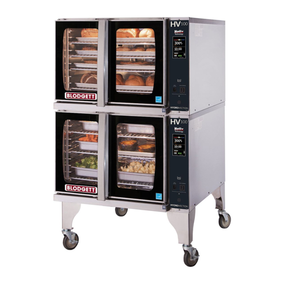
Installation Oven Description & Specifications aBOUT THE HYdROVECTIOn Blodgett Hydrovection ovens are quality produced using The practical oven doors, with viewing windows, have a high-grade stainless steel with first class workmanship. wide swing radius and handle which can be operated eas- ily, even with wet or greasy hands. - Page 5 Installation Oven Description & Specifications RaTInGS - HV-100G & HVH-100G TYPE OF GaS GaS InPUT VOLTaGE PHaSE aMPS MOTOR Natural 60,000 BTU/Hr 3/4 HP 208-240VAC, 3 phase, 50/60 Hz 208/240 Propane 60,000 BTU/Hr 3/4 HP 208-240VAC, 3 phase, 50/60 Hz 208/240 3/4”...
-
Page 6: Utility Connections - Standards And Codes
Local installation codes and/or require- ments may vary. If you have any questions regarding the proper installation and/or operation of your appliance, please contact your local distributor. If you do not have a local distributor, please call Blodgett at 0011-802-658- 6600. -
Page 7: Oven Location And Ventilation
Local installation codes and/or require- ments may vary. If you have any questions regarding the proper installation and/or operation of your unit, please contact your local distributor. If you do not have a local distributor, please call Blodgett at 0011-802-658-6600. -
Page 8: Leg Attachment
Installation Leg attachment LEG OPTIOnS aTTaCHMEnT 1. Align the threaded stud on one of the front legs to the bolt hole located the bottom corner of the appliance. Turn the leg clockwise and tighten to the nearest full turn. 2. Align the leg plate holes with the bolt holes. Secure with the two 1/2”... -
Page 9: Caster Attachment
Installation Caster attachment CaSTERS FOR SInGLE OVEnS PROFILE CaSTERS FOR dOUBLE STaCk OVEnS 1. Attach the legs as described. 1. Place a level on the floor where the casters are to rest. 2. Pry the adjustable feet out of the legs. 2. -
Page 10: Stacking
Installation Stacking 1. Attach the legs or casters to the bottom oven. WaRnInG!! 2. Place the top oven on the bottom oven. Be sure all Stacking should be performed by qualified four sides are flush. installation personnel only. The ovens are heavy. -
Page 11: Plumbing Connections
Installation Plumbing Connections WaTER COnnECTIOn Specific water/drain connection for City of Los Ange- NOTE: Must use COLD WATER ONLY. 1. Each drain line from the appliance shall be routed Connect the appliance to quality water via a pressure without dips or sags to terminate above the flood level hose with 3/4”... -
Page 12: Electrical Connections
ON this can cause an inadvertent trip of the able side panel. appliance’s ground fault interrupter (GFCI). Some GFCIs are more sensitive than others. Blodgett has qualified the NOTE: Disconnect the power supply to the appliance Pass and Seymour brand, part number 2095, 20 A, 125 before servicing. -
Page 13: Gas Connection
Installation Gas Connection GaS PIPInG Maximum Capacity of Iron Pipe in Cubic Feet of natural Gas Per Hour A properly sized gas supply system is essential for maxi- mum oven performance. Piping should be sized to pro- (Pressure drop of 0.5 Inch W.C.) vide a supply of gas sufficient to meet the maximum de- mand of all appliances on the line without loss of pressure nOMInaL SIzE, InCHES... - Page 14 The oven and its individual shutoff valve must be discon- please contact your local distributor. If you do not have a nected from the gas supply piping system during any local distributor, please call Blodgett Combi at 0011-802- pressure testing of that system at test pressures in ex- 658-6600.
-
Page 15: Posted In A Prominent Lo- Gas Hose Restraint
If you do not have a returned to its original position. local distributor, please call Blodgett Combi at 0011-802- 658-6600. Quick Connect Attachment Plate... -
Page 16: Operation
DO NOT use tools to turn off the gas control. If the operating instructions. They are the key to the success- gas cannot be turned off manually do not try to re- ful operation of your Blodgett oven. pair it. Call a qualified service technician. SaFETY TIPS •... -
Page 17: Standard Control
Operation Standard Control NOTE: Not available on HVH-100E and HVH-100G. COnTROLS IdEnTIFICaTIOn 1. MODE SELECTOR SWITCH - turns power to the oven on or off. Allows selection of Hydro, Hydro Max, Hot Air, or Cool Down Modes. 2. DISPLAY - displays time and temperature informa- tion. - Page 18 Operation Standard Control TIMER COOkInG PROBE COOkInG 1. Press the TIMER/PROBE KNOB (8) to select the tim- 1. Press the TIMER/PROBE knob (8) to select the er mode. The TIMER LED lights. probe setpoint mode. The PROBE SETPOINT LED (7) lights. 2.
-
Page 19: Menuselect™ Control
Operation MenuSelect™ Control NOTE: Not available on HVH-100E and HVH-100G. COnTROL dESCRIPTIOn 1. START/STOP KEY - press to start, cancel or pause the bake HV-100G 2. COOL DOWN KEY - initiates oven cool down cycle 3. BAKE MORE KEY - press at the end of a bake cycle to add additional bake time in one minute increments. - Page 20 Operation MenuSelect™ Control OVEn STaRTUP PROGRaMMEd COOkInG 1. Be sure the shutoff switch and/or circuit breaker 1. Turn the DIAL (1) until the name of the product is switch below the control panel are in the on position. highlighted. Press the center of the dial to select. The The display flashes OFF PRESS POWER KEY TO oven preheats to the programmed temperature in the START.
- Page 21 Operation MenuSelect™ Control 6. Connect the core probe to the PROBE CONNEC- Oven Shutdown TION (19) at the bottom of the control. 1. Press the COOL DOWN KEY (2). The display reads AUTO COOL DOWN ACTUAL TEMP. To speed up NOTE: Do not connect the probe before the cook the cool down process, open the doors and press the mode has been selected.
- Page 22 Operation MenuSelect™ Control PROdUCT PROGRaMMInG Entering the Program Mode 4. Rotate the dial to select the desired cooking mode. Choose from Hydro or Hot Air. Press the center of the 1. Press the PROGRAM KEY (13). If the control is pass- dial to set the cook mode.
- Page 23 Operation MenuSelect™ Control USInG THE USB PORT Programming Oven Setup 1. With the power on, remove the cover of the USB port These menus allow the manager to set up basic oven (20) and insert the USB drive. functions 1. Turn the dial to highlight OVEN SETUP. Press the 2.
-
Page 24: Smarttouch Touchscreen Control
Operation SmartTouch Touchscreen Control COnTROL dESCRIPTIOn 1. DISPLAY - displays information related to oven func- tion and/or programming. 2. USB Port and COVER - Use to transfer recipes and data to/from the control 3. CORE PROBE CONNECTION - plug core tempera- ture probe in here when using probe cooking 4. - Page 25 Operation SmartTouch Touchscreen Control Fan Speed - With the FAN icon highlighted, press the Lights - At any time the lights can be turned on or off fan speed text (Gentle, Low, High or Turbo). When by toggling the LIGHT icon. Turbo is displayed, press the text again to reduce the 3.
- Page 26 Operation SmartTouch Touchscreen Control Temp Probe Cooking Time Steam on Demand Hot Air Mode Hydro Mode Fan Speed Fan Reversal Increment Lights Vent Position Figure 12...
- Page 27 Operation SmartTouch Touchscreen Control MEnU MOdE COOkInG 1. On a manual screen, press the ESC key to exit the 4. Within the food category, select the desired product screen. you wish to cook. 2. Select the MENU key to cook using the prepro- grammed menu items.
- Page 28 Operation SmartTouch Touchscreen Control SHELF COOkInG 1. Select the SHELF COOKING key. 3. During the cook cycle, individual shelf cook timers will count down as the product is cooked. If you wish to cancel the bake, you can press the STOP ALL key, or you can stop individual shelves.
- Page 29 Operation SmartTouch Touchscreen Control EdITInG a MEnU 1. Select the MENU/EDIT icon to edit the recipes in the 3. To edit an existing item, select the item while the EDIT menu mode. ITEMS key is highlighted. To delete an Item, select the item while the DELETE key is highlighted.
- Page 30 Operation SmartTouch Touchscreen Control 4. Each recipe is made up of steps containing seven settings - temperature, time, fan, etc. A new step is needed when you desire a different setting within a step. To edit a setting within a particular step, press the icon for that setting.
- Page 31 Operation SmartTouch Touchscreen Control EdITInG a CaTEGORY 1. Select the MENU/EDIT icon to edit the recipes in the To delete a category, select the category while the menu mode. DELETE key is highlighted. To create a new category, select the NEW ? icon while the EDIT key is highlighted.
- Page 32 Operation SmartTouch Touchscreen Control 5. To edit the category icon, press the category icon dis- 6. To edit items within a category, press the SELECT played in the category edit screen. The Select Icon ITEMS key on the edit category screen. screen is displayed.
- Page 33 Operation SmartTouch Touchscreen Control CREaTInG nEW MEnU ITEMS 5. Program the recipe steps - Each recipe is made up of steps containing seven settings - temperature, 1. Select the EDIT ITEMS key. time, fan, etc. A new step is needed when you desire a different setting within a step.
- Page 34 Operation SmartTouch Touchscreen Control CREaTInG nEW CaTEGORIES 1. Select the EDIT CATEGORIES key. 4. Press EDIT NAME. A keyboard will appear. Enter the desired name. Press ENTER when finished to return to the previous screen. 5. Press SELECT ITEMS. Select items to be filed in the new category.
- Page 35 Operation SmartTouch Touchscreen Control TRanSFERRInG RECIPES USInG THE USB 1. Return to the power screen. To Store Menu data to a USB 1. Press the STORE MENU DATA to USB key to trans- fer recipes to the USB. Figure 32 Figure 34 2.
- Page 36 Operation SmartTouch Touchscreen Control 3. The status screen appears to display the download status. The display returns to the previous screen when download is complete. Figure 38 Figure 36 3. The overwrite warning screen appears. Press YES to continue 4. Press the ESC key to exit USB screen. To Retrieve Menu data from USB 1.
- Page 37 Operation SmartTouch Touchscreen Control COOL dOWn 1. To cool down the unit, press the COOL DOWN icon. 2. The oven will toggle between cooling and open door in yellow until the oven is cool. Once cool, the oven will go to standby. NOTE: If the oven is shut down with the circuit breaker switch at the bottom of the front panel, the display will return to the power...
-
Page 38: Uids In The Vicinity Of This Or Any Spray Bottle Operating Procedure
Maintenance Spray Bottle Operating Procedure NOTE: Only use a commercial oven cleaner/degreaser WaRnInG!! with the spray bottle. DO NOT use chemicals that are not intended as oven cleaners. See Protective clothing and eyewear should be chemical manufacturer’s information for intended worn while using cleaning agents. -
Page 39: Cleaning And Preventive Maintenance
Maintenance Cleaning and Preventive Maintenance CLEanInG THE InTERIOR On stainless interiors, deposits of baked on splatter, oil, grease or light discoloration may be removed with a daily Cleaning good non toxic industrial stainless steel cleaner. Ap- Daily cleaning of the appliance is essential for sanitation, ply cleaners when the oven is cold and always rub with and to ensure against operational difficulties. - Page 40 The Hydro- vection requires no lubrication. Contact the factory, the Figure 43 factory representative or a local Blodgett service com- pany to perform maintenance and repairs should they be 4. Remove the fan guard.