Blodgett S1820 Installation Operation & Maintenance
Conveyor oven
Hide thumbs
Also See for S1820:
- Brochure (3 pages) ,
- Installation, operation and maintenance instructions (62 pages)
Table of Contents
Advertisement
Advertisement
Table of Contents
Troubleshooting

Related Manuals for Blodgett S1820


Summary of Contents for Blodgett S1820
- Page 2 IMPORTANT WARNING: IMPROPER INSTALLATION, ADJUSTMENT, ALTERATION, SERVICE OR MAINTENANCE CAN CAUSE PROPERTY DAMAGE, INJURY OR DEATH. READ THE INSTALLATION, OPERATING AND MAINTENANCE IN- STRUCTIONS THOROUGHLY BEFORE INSTALLING OR SERVICING THIS EQUIPMENT FOR YOUR SAFETY Do not store or use gasoline or other flammable vapors or liquids in the vicinity of this or any other appliance.
- Page 3 THE REPUTATION YOU CAN COUNT ON For over a century and a half, The Blodgett Oven Company has been building ovens and nothing but ovens. We’ve set the industry’s quality standard for all kinds of ovens for every foodservice operation regardless of size, application or budget.
-
Page 5: Table Of Contents
B. Ventilation ..............35 III. ELECTRICAL CONNECTION INFORMATION FOR IV. MAINTENANCE - EVERY 6 MONTHS ......35 S1820 OVENS............13 S1820 ELECTRIC OVEN KEY SPARE PARTS .... 36 IV. ELECTRIC SUPPLY FOR ELECTRIC-HEATED KEY SPARE PARTS KIT ..........36 OVENS ..............12... - Page 6 NOTES...
-
Page 7: Model Identification
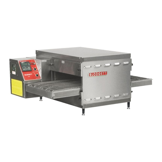
SECTION 1 DESCRIPTION I. MODEL IDENTIFICATION The Blodgett S1820 may be used either as a single oven or stacked for use as double or triple ovens. A single Blodgett S1820 Oven (Figure 1-1) is mounted on a base pad with legs. A double oven (Figure 1-2) consists of two, stacked, single ovens. -
Page 8: S1820 Electrical Specifications
SECTION 1 DESCRIPTION S1820 OVEN SPECIFICATIONS Conveyor Belt Width 18.00″ (457mm) Heating Zone Length 20.00″ (5098mm) Baking Area Square Feet 2.5 sq. ft. (0.23 sq. m.) Overall Dimension Standard Single Oven w/Legs 42.00″ (1067mm) L × 35.21″ (894mm) W ×... - Page 9 SECTION 1 DESCRIPTION II. COMPONENT FUNCTION (Figure 1-4) Figure 1-4. S1820 Oven Components Locations...
-
Page 10: Component Function
SECTION 1 DESCRIPTION II. COMPONENT FUNCTION A. Conveyor Motor and Conveyor Belt The conveyor belt is driven by a variable-speed electric motor (Figure 1-5) operating through a gear reducer. The motor speed is controlled by a digital control. The stain- less-steel wire belt can travel in either direction at variable rates ranging from 3 minutes to 30 minutes;... - Page 11 SECTION 1 DESCRIPTION Figure 1-6. Cooling Fan...
- Page 12 SECTION 1 DESCRIPTION Figure 1-7. Air Finger Componebts.
-
Page 13: Unloading
NOTE: The oven, when installed, must be electrically I. UNLOADING grounded in accordance with local codes, or in the ab- Your Blodgett S1820 Oven is shipped partially assembled. sence of local codes, with the National Electrical Code It will arrive in a carton on a crate. -
Page 14: S1820 Oven Installation Required Kits And Equipment
P/N 55312 ITEM PART NO. DESCRIPTION 48392 INSULATION BOTTOM TRAY 48394 BOTTOM TRAY WELDMENT 48396 TOP COVER 51387 SCREW MSSLT THREAD 8-32 × 1/2, 18-8 M3828 PIN, ALIGNMENT 55310 OWNER'S OPERATING & INSTALLATION MANUAL Figure 2-1. S1820 Electric Oven Installation Parts... - Page 15 SECTION 2 INSTALLATION Figure 2-5. MODEL S1820 SINGLE OVEN DIMENSIONS The Opening Height is Adjustable from 2-1/4 inch minimum to 3-3/4 inch maximum in 1/2 inch increments.
- Page 16 SECTION 2 INSTALLATION Figure 2-6. MODEL S1820 DOUBLE OVEN DIMENSIONS The Opening Height is Adjustable from 2-1/4 inch minimum to 3-3/4 inch maximum in 1/2 inch increments.
- Page 17 SECTION 2 INSTALLATION Figure 2-7. MODEL S1820 TRIPLE OVEN DIMENSIONS The Opening Height is Adjustable from 2-1/4 inch minimum to 3-3/4 inch maximum in 1/2 inch increments.
-
Page 18: Utility Rough-In Dimensions And Positioning For S1820 Ovens
ELECTRIC SUPPLY TO BE PROVIDED BY CUSTOMER CIRCUIT BREAKER Separate circuit breaker with lockout/tagout electrical Figure 2-9. Typical S1820 Oven(s) Installation shutoff for each oven. Wire each oven separately. 50 Amp circuit breaker for 208-240V, or 30 Amp circuit ELECTRICAL RATING breaker for 380-480V. -
Page 19: Electrical Connection Information For S1820 Ovens
Australian Code AG601; or other applicable regulations. amperes. A fused disconnect switch or a main circuit breaker Typical specifications for each S1820 Oven are 208V or (customer furnished) MUST be installed in the electric 240V, 1-phase, 3-wire, 8.3kW; this oven requires 50- supply line for each oven;... - Page 20 SECTION 2 INSTALLATION NOTES...
-
Page 21: Control Functions
SECTION 3 OPERATION SECTION 3 OPERATION I. CONTROL FUNCTIONS Figure 3-1. S1820 Oven Control Functions WARNING A possibility of injury from rotating parts and electric shock exists in this oven. Never disassemble or clean the oven with the BLOWER switch or any other oven control turned “ON”... -
Page 22: Component Information And Location
SECTION 3 OPERATION II. COMPONENT INFORMATION AND If the temperature inside the oven is over 180°F (82°C) the main blower will continue to run after the blower LOCATION (Figures 3-1 and 3-2) switch is turned to the “OFF” or “O” position. A. -
Page 23: Conveyor
SECTION 3 OPERATION E. Conveyor The on-off switch for the conveyor motor is on the control panel. Also on the control panel is the digital conveyor speed control. The digital control can be adjusted from 3 min. to 30 min. bake time (conveyor speed). Refer to Figure 3-3. -
Page 24: Step-By-Step Operation
SECTION 3 OPERATION 4. Set the temperature controller to the desired baking WARNING temperature. OVEN MUST BE KEPT CLEAR OF NOTE: For complete temperature controller operation COMBUSTIBLES AT ALL TIMES. instructions refer to Step C. 5. Turn the HEAT switch (Figure 3-6) to the “ON” or “I” III. - Page 25 SECTION 3 OPERATION S1820 Figure 3-6. Control Panel...
-
Page 26: Normal Operation - Step-By-Step
SECTION 3 OPERATION IV. NORMAL OPERATION - STEP-BY-STEP Wait for the oven to heat to the setpoint temperature. Higher setpoint temperatures will require a longer wait. A.Daily Startup Procedure The oven can reach a temperature of 500°F (232°C) in approximately 15 minutes. Check that the circuit breaker/fused disconnect is in the on position. - Page 27 SECTION 3 OPERATION Display "HEAT ON" Shows the Set Point Light or the Actual Tem- Lights when the perature in degrees burner is in Fahrenheit (F) or operation. Celsius (C). "SP LOCK" Light Lights when the "SET PT" set point is locked out from changes.
-
Page 28: Quick Reference: Troubleshooting
• Check that the set temperature and bake time settings are overcooked or rectly. correct. undercooked. IF THESE STEPS FAIL TO RESOLVE THE PROBLEM, CONTACT YOUR LOCAL BLODGETT AUTHORIZED SERVICE AGENT. A SERVICE AGENCY DIRECTORY IS SUPPLIED WITH YOUR OVEN. -
Page 29: Section 4 Maintenance
SECTION 4 MAINTENANCE SECTION 4 MAINTENANCE WARNING Possibility of injury from rotating parts and electrical shock exist in this oven. Turn off and lockout or tagout electrical supply to oven(s) before attempting to disassemble, clean or service oven(s). Never disas- semble or clean the oven with the blower switch or any other part of the oven turned on. -
Page 30: Maintenance - Daily
SECTION 4 MAINTENANCE I. MAINTENANCE - DAILY D. Crumb Pans (Figure 4-2) A. Exterior WARNING Everyday you should clean the outside of the oven with a soft cloth and mild detergent. Crumb pan is extremely hot while oven is operating. Allow oven to cool before removing crumb pan. -
Page 31: Maintenance - Monthly
To clean the interior, you have to disassemble You can order non-caustic cleaner from your local autho- some parts of the oven. rized Blodgett Parts Distributor in the quantities listed When cleaning your Series S1820 Oven note the below: following: Part #... - Page 32 SECTION 4 MAINTENANCE 4. Lift conveyor and remove chain. 5. Lift other side of conveyor and push toward other side. 6. Remove conveyor as shown. Figure 4-4. Figure 4-6. Figure 4-5. Figure 4-7. CAUTION Be careful not to bump the drive sprocket while handling the conveyor, to avoid damaging the drive shaft.
-
Page 33: Air Fingers Disassembly For Cleaning
SECTION 4 MAINTENANCE B. Air Fingers Disassembly For Cleaning 1. As the air fingers are removed use a felt pen to mark all parts of the fingers. This includes the finger manifold, inner plate and the outer plate (refer to Figure 1-9). Fingers are marked in the order shown;... -
Page 34: Reassembly Of Air Fingers
SECTION 4 MAINTENANCE 5. To remove the inner plate, pull the plate out and then up. C. Reassembly of Air Fingers 1. Air fingers are made up of one inner plate, one outer plate and the finger housing manifold. Be sure to match up the markings (T1, T2, T3, etc.) on all the parts of the air fingers as you are reassembling. - Page 35 SECTION 4 MAINTENANCE 4. Replace the air fingers by pushing in at the back side. Remember to replace them according to the numbers marked on them when they were removed. They must go back in the same way they came out. IMPORTANT: When inserting fingers the tab on the outer plate must be in the groove as shown in Figure 4-18.
-
Page 36: Reinstall End Plugs
SECTION 4 MAINTENANCE D. Reinstall End Plugs 1. Reinstall lower end plug. Be sure to tighten the wing screw on the end plug. 2. Reinstall conveyor. 3. Reinstall upper end plug. Be sure to tighten two wing screws on the end plug. Figure 4-19. -
Page 37: Conveyor Reassembly Into Oven
SECTION 4 MAINTENANCE E. Conveyor Reassembly Into Oven F. Checking Conveyor Belt Tension 1. Lift conveyor and position it in oven as shown. WARNING NOTE: Conveyor may be inserted into either end of oven. Oven conveyor belt must be cool when adjusting If it is to be installed from the non-drive end of the oven the belt. -
Page 38: Conveyor Belt Link Removal
SECTION 4 MAINTENANCE G. Conveyor Belt Link Removal 4. Unhook the link to be removed. 1. Using long nose pliers, an entire link can be removed 5. Pull up on the belt link section and remove. Do not with the conveyor assembly either in or out of the oven. discard the link removed as it may be used for making Position master links at end of conveyor as shown in spare master links. -
Page 39: Attaching Drive Chain
SECTION 4 MAINTENANCE 6. Reconnect the inside master links (Figure 4-29.) H. Attaching Drive Chain 1. If drive sprocket assembly was removed reassemble it into the conveyor drive shaft. Be sure flat on end of drive shaft aligns with set screw in conveyor shaft collar. Once in place tighten 3/32″... -
Page 40: Maintenance - Every 3 Months
A. Check brushes on D.C. conveyor motor, when worn to less than 1/10″ (2.4mm), replace the brushes. NOTE: It is recommended that the 3-month mainte- B. Check your oven venting system. nance be performed by an authorized Blodgett technician. IMPORTANT NOTICES: • Installation of replacement parts requiring access to the interior of the oven is permitted only by an authorized service technician. -
Page 41: S1820 Electric Oven Key Spare Parts
* The proper location for the thermocouple is as follows: 1) Temperature sensing is located on the entrance end of the unit on the bottom, 2) High limit is located on the exit end of the unit on the top, 3) High limit on the S1820 is 600 degree's. Figure 4-36. - Page 42 SECTION 4 MAINTENANCE NOTES...
-
Page 43: Section 5 Troubleshooting
SECTION 5 TROUBLESHOOTING SECTION 5 TROUBLESHOOTING PROBLEM: PROBLEM: PRODUCTS ARE OVERCOOKED OVEN BLOWER AND CONVEYOR OPER- OR UNDERCOOKED ATE, YET THE OVEN IS NOT HEATING Reset the temperature controller Check for correct Check for correct to a new setting (above 200°F), setting of conveyor setting on tempera- after turning the BLOWER switch... - Page 44 SECTION 5 TROUBLESHOOTING NOTES...
- Page 45 SECTION 6 PARTS LIST SECTION 6 - PARTS LIST...
- Page 46 SECTION 6 PARTS LIST...
-
Page 47: Section 6 - Parts List
SECTION 6 PARTS LIST... - Page 48 SECTION 6 PARTS LIST...
-
Page 49: Relay Panel
SECTION 6 PARTS LIST... - Page 50 SECTION 6 PARTS LIST...
-
Page 51: Blower Assembly
SECTION 6 PARTS LIST... - Page 52 SECTION 6 PARTS LIST...
-
Page 53: Control Panel
SECTION 6 PARTS LIST... - Page 54 SECTION 6 PARTS LIST...
-
Page 55: Single Conveyor
SECTION 6 PARTS LIST... - Page 56 SECTION 6 PARTS LIST NOTES...
-
Page 57: Section 7 Electrical Schematics
SECTION 7 ELECTRICAL SCHEMATICS SECTION 7 ELECTRICAL SCHEMATICS... -
Page 58: Wiring Diagram, E380-480V 50/60/1, S1820
SECTION 7 ELECTRICAL SCHEMATICS... -
Page 59: Wiring Diagram, E230-240V Ce S1820
SECTION 7 ELECTRICAL SCHEMATICS... -
Page 60: Wiring Diagram, E380-400V Ce S1820
SECTION 7 ELECTRICAL SCHEMATICS... - Page 61 SECTION 7 ELECTRICAL SCHEMATICS NOTES...
- Page 62 Service Association (CFESA). We recognize and applaud CFESA's ongoing efforts to improve the quality of technical service in the industry. G.S. Blodgett Corporation • 50 Lakeside Avenue, Box 586 • Burlington, Vermont 05402 • USA Telephone (800) 331-5842, (802) 860-3700 • Fax: (802) 864-0183 www.blodgettcorp.com...