Table of Contents
Advertisement
Quick Links
Advertisement
Table of Contents

Related Manuals for Texas Instruments HDC2022EVM


Summary of Contents for Texas Instruments HDC2022EVM
- Page 1 HDC2022EVM User's Guide Literature Number: SNIU039 December 2019...
-
Page 2: Table Of Contents
Device Address Configuration ................Reducing the Sensor's Thermal Mass ..................Updating Firmware on HDC2022EVM ........................Board Layout ......................... Schematic ....................HDC2022EVM Bill of Materials Table of Contents SNIU039 – December 2019 Submit Documentation Feedback Copyright © 2019, Texas Instruments Incorporated... - Page 3 ..............HDC2022EVM: PC Interface and Sensor Module ............HDC2022EVM: PC Interface and Smaller Sensor Module .......... HDC2022EVM: Pads for I2C and Supply of the Smaller Sensor Module ............... HDC2022EVM Spy-Bi-Wire programming connections ............UniFlash Launch Screen, MSP430F5528 device selected......................
-
Page 4: Trademarks
User's Guide SNIU039 – December 2019 HDC2022EVM User's Guide The Texas Instruments HDC2022EVM evaluation module (EVM) enables designers to evaluate the operation and performance of the HDC2022 Relative Humidity and Temperature Sensor. The EVM contains one HDC2022 (see Table Table 1. Device and Package Configurations... -
Page 5: Quick Start
2. Reload the browser window after installation to access the home screen of the HDC2022EVM GUI. 3. Connect the HDC2022EVM to the USB port of your computer via USB. Drivers for the device will install automatically and the GUI will connect to the EVM. -
Page 6: Evm Gui
EVM GUI Software Setup The PC GUI software for the HDC2022EVM runs on TI's GUI composer framework. The software is available as a live version which runs in your browser, and is available as a download for offline use. The software is compatible with Windows, Mac, and Linux Operating systems. -
Page 7: Gui Operation
GUI Operation www.ti.com GUI Operation The section describes how to use the HDC2022EVM GUI Home Tab The Home Tab is shown at software launch. The Learn More link displays the key features and a functional diagram for the HDC2022 device. The icons on the left side of the screen are shortcuts which can be used for navigation to other tabs within the GUI. -
Page 8: Data Capture Tab
Data Capture Tab The Data Capture tab reports the temperature and humidity from the HDC2022 device included on the HDC2022EVM. To enable data capture, ensure that an auto-read delay from the drop down menu at the top of the page is selected. -
Page 9: Evm Settings Tab
Each selection option/button on this tab has a specific function as described below: • I2C Frequency: Change the communication frequency between the control board and HDC2022EVM. • I2C Address: Selects the address option of the HDC2022. -
Page 10: Device Configuration
Device Configuration The Device Configuration tab allows for easy configuration and setup of the HDC2022 device included on the HDC2022EVM. If immediate write mode is selected on the Section 4.5, then changes made in the selection boxes will be written to the HDC2022 device as soon as possible. -
Page 11: Registers Tab
These settings give the user control over I2C bus activity, and enable individual transactions which can be easily observed via oscilloscope, logic analyzer, or bus-sniffing device. Figure 8. Register Tab of HDC2022EVM GUI SNIU039 – December 2019... -
Page 12: Collateral Tab
The Collateral tab contains links to articles, guides, reports, and videos which are relevant to the HDC2022 device. This includes the device datasheet and EVM User's Guide. Figure 9. Collateral Tab of HDC2022EVM GUI HDC2022EVM User's Guide SNIU039 – December 2019 Submit Documentation Feedback Copyright ©... -
Page 13: Evm Hardware
EVM Operating Conditions The HDC2022EVM power is supplied via the USB connector. The LDO (U4) converts the 5V from the USB to 3.3V used by the HDC2022 and the MSP430. The EVM may be directly inserted into a USB port on a PC or laptop, or may be connected to the latter using the appropriate USB cable. -
Page 14: Device Address Configuration
Figure 11. HDC2022EVM : Sensor Module To change the I2C address to 0x40, remove 0 Ω resistor R4 (refer to Figure 12 Figure 12. HDC2022EVM: Layout Resistors for I2C Address Setting - Top Table 3. I2C Address ADDR HDC2022 ADDRESS... -
Page 15: Reducing The Sensor's Thermal Mass
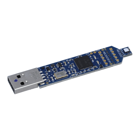
EVM Hardware www.ti.com Reducing the Sensor's Thermal Mass The HDC2022EVM can be broken into 2 sections to isolate the thermal mass of the µC from the HDC2022. Figure 13 shows the board perforations that allow the two sections to be broken apart. -
Page 16: Hdc2022Evm: Pads For I2C And Supply Of The Smaller Sensor Module
EVM Hardware www.ti.com Figure 15. HDC2022EVM: Pads for I2C and Supply of the Smaller Sensor Module HDC2022EVM User's Guide SNIU039 – December 2019 Submit Documentation Feedback Copyright © 2019, Texas Instruments Incorporated... -
Page 17: Updating Firmware On Hdc2022Evm
The primary method for flashing the HDC2022EVM is Spy-Bi-Wire. In order to reflash the firmware you will need the following: •... -
Page 18: Uniflash Launch Screen, Msp430F5528 Device Selected
Figure 17. UniFlash Launch Screen, MSP430F5528 device selected. 8. Browse to the firmware file named USB2ANY-F5528-24MHZ.txt and select Load Image. Upon successful programming, the firmware image will be loaded and the HDC2022EVM will automatically restart. The HDC2022EVM firmware upgrade is then complete. -
Page 19: Board Layout
Board Layout www.ti.com Board Layout Figure 18 Figure 19 show the board layout for the HDC2022EVM. Figure 18. Top Layer Routing Figure 19. Bottom Layer Routing SNIU039 – December 2019 HDC2022EVM User's Guide Submit Documentation Feedback Copyright © 2019, Texas Instruments Incorporated... -
Page 20: Schematic
Schematic www.ti.com Schematic Figure 20. HDC2022EVM Schematic HDC2022EVM User's Guide SNIU039 – December 2019 Submit Documentation Feedback Copyright © 2019, Texas Instruments Incorporated... -
Page 21: Hdc2022Evm Bill Of Materials
Xtal, 7.2x1.3x5.2mm ABMM-24.000MHZ-B2-T FID1, FID2, Fiducial mark. There is nothing to buy or mount. FID3 J1, J2 Header, 100mil, 5x1, Gold, TH 5x1 Header TSW-105-07-G-S SNIU039 – December 2019 HDC2022EVM User's Guide Submit Documentation Feedback Copyright © 2019, Texas Instruments Incorporated... - Page 22 STANDARD TERMS FOR EVALUATION MODULES Delivery: TI delivers TI evaluation boards, kits, or modules, including any accompanying demonstration software, components, and/or documentation which may be provided together or separately (collectively, an “EVM” or “EVMs”) to the User (“User”) in accordance with the terms set forth herein.
- Page 23 www.ti.com Regulatory Notices: 3.1 United States 3.1.1 Notice applicable to EVMs not FCC-Approved: FCC NOTICE: This kit is designed to allow product developers to evaluate electronic components, circuitry, or software associated with the kit to determine whether to incorporate such items in a finished product and software developers to write software applications for use with the end product.
- Page 24 www.ti.com Concernant les EVMs avec antennes détachables Conformément à la réglementation d'Industrie Canada, le présent émetteur radio peut fonctionner avec une antenne d'un type et d'un gain maximal (ou inférieur) approuvé pour l'émetteur par Industrie Canada. Dans le but de réduire les risques de brouillage radioélectrique à...
- Page 25 www.ti.com EVM Use Restrictions and Warnings: 4.1 EVMS ARE NOT FOR USE IN FUNCTIONAL SAFETY AND/OR SAFETY CRITICAL EVALUATIONS, INCLUDING BUT NOT LIMITED TO EVALUATIONS OF LIFE SUPPORT APPLICATIONS. 4.2 User must read and apply the user guide and other available documentation provided by TI regarding the EVM prior to handling or using the EVM, including without limitation any warning or restriction notices.
- Page 26 Notwithstanding the foregoing, any judgment may be enforced in any United States or foreign court, and TI may seek injunctive relief in any United States or foreign court. Mailing Address: Texas Instruments, Post Office Box 655303, Dallas, Texas 75265 Copyright © 2019, Texas Instruments Incorporated...
- Page 27 TI products. TI’s provision of these resources does not expand or otherwise alter TI’s applicable warranties or warranty disclaimers for TI products. Mailing Address: Texas Instruments, Post Office Box 655303, Dallas, Texas 75265 Copyright © 2019, Texas Instruments Incorporated...