Table of Contents
Advertisement
Quick Links
www.ti.com
User's Guide
HDC3020EVM User Guide
This is the user guide for the HDC3 family, an integrated Relative Humidity (RH) and Temperature sensor
that provides high accuracy with ultra-low power consumption. This family of sensors is equipped with a Drift
Correction feature to further compensate and improve sensor drift due to contaminants and aging. The HDC3
family is ready to use out of the box and does not require any further calibration.
The hardware is populated with the HDC3020, an open cavity commercial version. Users can replace the
HDC3020 device on this EVM with any of the devices from the HDC3020 family. It can be used to evaluate
HDC3021 (removable tape) and HDC3022 (IP67 filter membrane), and their respective automotive versions
because the HDC3 family are pin-to-pin and 100% software compatible.
This module and the GUI are designed to provide the user a quick setup to evaluate the device. This document
includes the details of the EVM hardware and the software installation.
1
Introduction.............................................................................................................................................................................2
Start...............................................................................................................................................................................3
Hardware.........................................................................................................................................................................4
3.1 EVM Power Supply............................................................................................................................................................
3.2 Input/Output Connectors....................................................................................................................................................
Configuration............................................................................................................................................5
3.4 Reducing Thermal Mass....................................................................................................................................................
Conditions.................................................................................................................................................7
GUI...................................................................................................................................................................................8
4.1 Live Software.....................................................................................................................................................................
Version....................................................................................................................................................................8
Operation..........................................................................................................................................................................9
Tab...........................................................................................................................................................................9
5.2 Data Capture Tab.............................................................................................................................................................
Tab.............................................................................................................................................................13
5.4 Collateral..........................................................................................................................................................................
Layout.........................................................................................................................................................................15
7
Schematic..............................................................................................................................................................................16
8 HDC3020EVM Build of Materials.........................................................................................................................................
9 Revision History...................................................................................................................................................................
Trademarks
All trademarks are the property of their respective owners.
SNAU267A - JUNE 2021 - REVISED JUNE 2021
Submit Document Feedback
ABSTRACT
Table of Contents
Copyright © 2021 Texas Instruments Incorporated
Table of Contents
4
4
6
8
10
14
17
18
HDC3020EVM User Guide
1
Advertisement
Table of Contents

Related Manuals for Texas Instruments HDC3020EVM


Summary of Contents for Texas Instruments HDC3020EVM
-
Page 1: Table Of Contents
5.3 EVM Settings Tab................................13 5.4 Collateral..................................6 Board Layout..................................15 Schematic....................................16 8 HDC3020EVM Build of Materials............................9 Revision History................................... Trademarks All trademarks are the property of their respective owners. SNAU267A – JUNE 2021 – REVISED JUNE 2021 HDC3020EVM User Guide Submit Document Feedback... -
Page 2: Introduction
PC through a USB port. The EVM is designed to be broken into two sections, if desired. The sensor section can be separated from the MCU section of the board to reduce thermal mass surrounding the HDC3020. The HDC3020EVM is configured by default to use the HDC3020 device with I address 0x44 (7 bit). -
Page 3: Quick Start
2. Reload the browser window after installation to access the home screen of the HDC3020EVM GUI. 3. Connect the HDC3020EVM to the USB port of your computer through the USB. Drivers for the device will install automatically and the GUI will connect to the EVM. -
Page 4: Evm Hardware
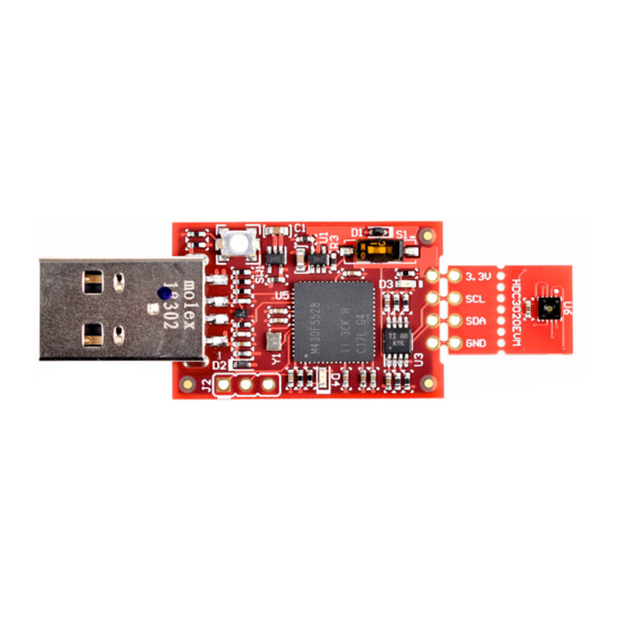
Figure 3-1. HDC3020EVM 3.1 EVM Power Supply The HDC3020EVM power is supplied through the USB connector. The interface is used to access the device’s registers and read the conversion data from the HDC3020 through the I C communication protocol. The LDO (U4) converts the 5 V from the USB to 3.3 V used by the HDC3020 and the MSP430. -
Page 5: Device Address Configuration
EVM Hardware 3.3 Device Address Configuration The HDC3020 can support 4 I C addresses, but the HDC3020EVM can only support one fixed I C address: 0x44 (7 Bit). Figure 3-2. HDC3020 Sensor Module SNAU267A – JUNE 2021 – REVISED JUNE 2021... -
Page 6: Reducing Thermal Mass
EVM Hardware www.ti.com 3.4 Reducing Thermal Mass The HDC3020EVM can be broken into 2 sections to isolate the thermal mass of the μC from the HDC3020. Figure 3-3 shows the board perforations where the two sections can break apart. Figure 3-3. PC Interface and Sensor Module The purpose of the header connector is to isolate the heat source from the HDC3020. -
Page 7: Evm Operating Conditions
EVM Hardware Alternatively it is possible to connect the sensor module to a custom microcontroller. Figure 3-5. Bottom Layer of the HDC3020EVM 3.5 EVM Operating Conditions The controller and device sides of the EVM have different temperature limits as shown in Table 3-3. -
Page 8: Evm Gui
The live software currently works within Chrome, Firefox and Safari browsers. Internet Explorer and Edge browsers are not supported. Users can access the live version through one of the following actions: 1. Go to the HDC3020EVM Tool page on TI.com and click the View button. 2. Go to dev.ti.com/gallery... -
Page 9: Gui Operation
GUI. They are identical to the icons on the bottom half of the Home page. If the HDC3020EVM is connected to the PC and powered on, the Hardware Connected icon will appear on the left corner of the status bar. -
Page 10: Data Capture Tab
5.2 Data Capture Tab The Data Capture tab reports the temperature and humidity from the HDC3020 device included on the HDC3020EVM. Each selection option/button on this tab has a specific function as described below: • Measurement Mode tab – Measurement mode: Can select Trigger-On Demand (one-shot mode) or the Auto Measurement mode with the appropriate frequency –... - Page 11 Mid Power and Max Power Figure 5-3. Thermal Isolation Examples – This feature is currently only available for a demonstration purpose on the HDC3020EVM. The power settings are specifically chosen to correct the drift on the HDC3020EVM and code compensates for this layout.
- Page 12 Figure 5-4. Offset Register Displaying the HDC3020 Drift Offset – Abort: Aborts the drift Correction in the middle of an execution. HDC3020EVM User Guide SNAU267A – JUNE 2021 – REVISED JUNE 2021 Submit Document Feedback Copyright © 2021 Texas Instruments Incorporated...
-
Page 13: Evm Settings Tab
The EVM Settings tab allows for setup of features for the USB to I C bridge and EVM GUI. • C Frequency: Change the communication frequency between the control board and HDC3020EVM. • C Address: Selects the address option of the HDC3020. -
Page 14: Collateral
The Collateral tab contains links to articles, guides, reports, and videos which are relevant to the HDC3020 device. This includes the device data sheet and EVM user's guide. HDC3020EVM User Guide SNAU267A – JUNE 2021 – REVISED JUNE 2021 Submit Document Feedback Copyright © 2021 Texas Instruments Incorporated... -
Page 15: Board Layout
Board Layout 6 Board Layout Figure 6-1. Top Layer Routing Figure 6-2. Bottom Layer Routing SNAU267A – JUNE 2021 – REVISED JUNE 2021 HDC3020EVM User Guide Submit Document Feedback Copyright © 2021 Texas Instruments Incorporated... -
Page 16: Schematic
Not in version control Assembly Variant: Sheet: warrant that this design will meet the specifications, will be suitable for your application or fit for any particular purpose, or will operate in an implementation. Texas Instruments and/or its Drawn By: File: SENS067_SCH.SchDoc... -
Page 17: Hdc3020Evm Build Of Materials
HDC3020EVM Build of Materials 8 HDC3020EVM Build of Materials Designator Quantity Description Package Reference PartNumber C1, C6 CAP, CERM, 2.2 uF, 16 V, 0402 GRM155R61C225KE11D +/- 10%, X5R, 0402 C2, C7 CAP, CERM, 10 uF, 10 V, 0603 C1608X5R1A106M080AC... -
Page 18: Revision History
Changes from Revision * (June 2021) to Revision A (June 2021) Page • Changed Home Tab section..........................• Changed Data Capture Tab section........................10 HDC3020EVM User Guide SNAU267A – JUNE 2021 – REVISED JUNE 2021 Submit Document Feedback Copyright © 2021 Texas Instruments Incorporated... - Page 19 STANDARD TERMS FOR EVALUATION MODULES Delivery: TI delivers TI evaluation boards, kits, or modules, including any accompanying demonstration software, components, and/or documentation which may be provided together or separately (collectively, an “EVM” or “EVMs”) to the User (“User”) in accordance with the terms set forth herein.
- Page 20 www.ti.com Regulatory Notices: 3.1 United States 3.1.1 Notice applicable to EVMs not FCC-Approved: FCC NOTICE: This kit is designed to allow product developers to evaluate electronic components, circuitry, or software associated with the kit to determine whether to incorporate such items in a finished product and software developers to write software applications for use with the end product.
- Page 21 www.ti.com Concernant les EVMs avec antennes détachables Conformément à la réglementation d'Industrie Canada, le présent émetteur radio peut fonctionner avec une antenne d'un type et d'un gain maximal (ou inférieur) approuvé pour l'émetteur par Industrie Canada. Dans le but de réduire les risques de brouillage radioélectrique à...
- Page 22 www.ti.com EVM Use Restrictions and Warnings: 4.1 EVMS ARE NOT FOR USE IN FUNCTIONAL SAFETY AND/OR SAFETY CRITICAL EVALUATIONS, INCLUDING BUT NOT LIMITED TO EVALUATIONS OF LIFE SUPPORT APPLICATIONS. 4.2 User must read and apply the user guide and other available documentation provided by TI regarding the EVM prior to handling or using the EVM, including without limitation any warning or restriction notices.
- Page 23 Notwithstanding the foregoing, any judgment may be enforced in any United States or foreign court, and TI may seek injunctive relief in any United States or foreign court. Mailing Address: Texas Instruments, Post Office Box 655303, Dallas, Texas 75265 Copyright © 2019, Texas Instruments Incorporated...
- Page 24 TI products. TI’s provision of these resources does not expand or otherwise alter TI’s applicable warranties or warranty disclaimers for TI products.IMPORTANT NOTICE Mailing Address: Texas Instruments, Post Office Box 655303, Dallas, Texas 75265 Copyright © 2021, Texas Instruments Incorporated...