
Related Manuals for Texas Instruments HDC1050EVM


Summary of Contents for Texas Instruments HDC1050EVM
- Page 1 HDC1050EVM User 's Guide User's Guide Literature Number: SNAU181A June 2015 – Revised June 2015...
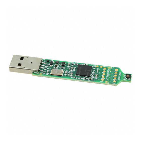
- Page 2 SNAU181A – June 2015 – Revised June 2015 HDC1050EVM User 's Guide Introduction The Texas Instruments HDC1050EVM evaluation module (EVM) enables designers to evaluate the operation and performance of the HDC1050 Relative Humidity and Temperature sensor. The EVM contains one HDC1050 (See Table Table 1.
-
Page 3: Input/Output Connector Description
This connector is used for communications with the PC and provides power for the EVM. Hardware Setup The HDC1050EVM power is supplied via the USB connector. The LDO (U4) converts the 5V from the USB to 3.3V used by the HDC1050 and the MSP430. The EVM may be directly inserted into a USB port on a PC or laptop, or may be connected to the latter using the appropriate USB cable. - Page 4 5. Read the license agreement and if you still wish to install the software, select “I accept the agreement” and click “Next” as shown in HDC1050EVM User 's Guide SNAU181A – June 2015 – Revised June 2015 Submit Documentation Feedback Copyright © 2015, Texas Instruments Incorporated...
- Page 5 “Program Files” should be chosen instead of the default. Figure 4. GUI Installer Installation Directory 7. Wait for all files to install SNAU181A – June 2015 – Revised June 2015 HDC1050EVM User 's Guide Submit Documentation Feedback Copyright © 2015, Texas Instruments Incorporated...
- Page 6 Figure 6. EVM Driver Installer Welcome Page 9. Wait for the driver to install HDC1050EVM User 's Guide SNAU181A – June 2015 – Revised June 2015 Submit Documentation Feedback Copyright © 2015, Texas Instruments Incorporated...
- Page 7 10. Click “Finish” after the driver has been installed Figure 8. EVM Driver Installer Complete 11. Click “Finish” to complete the software installation SNAU181A – June 2015 – Revised June 2015 HDC1050EVM User 's Guide Submit Documentation Feedback Copyright © 2015, Texas Instruments Incorporated...
- Page 8 Setup www.ti.com Figure 9. GUI Installer Complete HDC1050EVM User 's Guide SNAU181A – June 2015 – Revised June 2015 Submit Documentation Feedback Copyright © 2015, Texas Instruments Incorporated...
-
Page 9: Operation
Launch the GUI. A detailed description of the GUI operation is presented later in this document. Reducing the Sensor Thermal Mass The HDC1050EVM can be broken into 2 sections to isolate the thermal mass of the µC from the HDC1050. The yellow arrow in... -
Page 10: Gui Operation
The communications with the µC section is achieved through a 4-wire cable soldered at the pads accessible on the bottom layer of the PCB (Refer to Figure 12). Figure 12. HDC1050EVM Pads for I2C and Supply of the Smaller Sensor Section GUI Operation The section describes how to use the GUI Starting the GUI Follow these steps to start the GUI: 1. - Page 11 1. Attach the EVM to the computer via the USB port. 2. The GUI always shows the connection status on the bottom left corner of the GUI SNAU181A – June 2015 – Revised June 2015 HDC1050EVM User 's Guide Submit Documentation Feedback Copyright © 2015, Texas Instruments Incorporated...
- Page 12 EVMs from a single instance of the GUI. Figure 15. GUI Disconnected From EVM Figure 16. GUI Connected from EVM HDC1050EVM User 's Guide SNAU181A – June 2015 – Revised June 2015 Submit Documentation Feedback Copyright © 2015, Texas Instruments Incorporated...
-
Page 13: Navigating The Gui
1. Click “Menu” in the upper left corner Figure 17. GUI Menu Button 2. Select the desired page from the menu shown on the left SNAU181A – June 2015 – Revised June 2015 HDC1050EVM User 's Guide Submit Documentation Feedback Copyright © 2015, Texas Instruments Incorporated... - Page 14 Autoread will periodically request the register values on the device. Click the dropdown box next to “Auto Read” to select the update interval. HDC1050EVM User 's Guide SNAU181A – June 2015 – Revised June 2015 Submit Documentation Feedback Copyright © 2015, Texas Instruments Incorporated...
- Page 15 1. Double-click the current value of the register that needs to be changed. The text will turn into an editable text box SNAU181A – June 2015 – Revised June 2015 HDC1050EVM User 's Guide Submit Documentation Feedback Copyright © 2015, Texas Instruments Incorporated...
- Page 16 GUI will send a command to the EVM to update the device register Figure 21. Entering New Value for Register on Register Page HDC1050EVM User 's Guide SNAU181A – June 2015 – Revised June 2015 Submit Documentation Feedback Copyright © 2015, Texas Instruments Incorporated...
- Page 17 1. Hover the mouse over the desired bit to change Figure 23. Hovering Mouse Over Register Bit Value on Register Page SNAU181A – June 2015 – Revised June 2015 HDC1050EVM User 's Guide Submit Documentation Feedback Copyright © 2015, Texas Instruments Incorporated...
- Page 18 To read register values follow these steps. 1. Select the register to update by clicking any column of the register row in the table HDC1050EVM User 's Guide SNAU181A – June 2015 – Revised June 2015 Submit Documentation Feedback Copyright © 2015, Texas Instruments Incorporated...
- Page 19 2. Click the “Read Register” button to update the selected register’s current value and bit values in the table Figure 26. Reading the Current Device Register Value on Register Page SNAU181A – June 2015 – Revised June 2015 HDC1050EVM User 's Guide Submit Documentation Feedback Copyright © 2015, Texas Instruments Incorporated...
- Page 20 Figure 27. Save Register Values to File on Register Page 2. Choose a JSON file name and the directory to save it within. Then click “Save” HDC1050EVM User 's Guide SNAU181A – June 2015 – Revised June 2015 Submit Documentation Feedback Copyright © 2015, Texas Instruments Incorporated...
- Page 21 To load previously saved register settings from a JSON file follow these steps. 1. Click the button furthest right from the “Auto-Read” selection dropdown SNAU181A – June 2015 – Revised June 2015 HDC1050EVM User 's Guide Submit Documentation Feedback Copyright © 2015, Texas Instruments Incorporated...
- Page 22 2. Select the JSON file with the desired settings and click “Open” Figure 30. Selecting Previously Save Register Value JSON File HDC1050EVM User 's Guide SNAU181A – June 2015 – Revised June 2015 Submit Documentation Feedback Copyright © 2015, Texas Instruments Incorporated...
- Page 23 Select the drop down menu on top of the y-axis to choose the units of the graph. Available options include: Temperature and Humidity, and Raw Code. SNAU181A – June 2015 – Revised June 2015 HDC1050EVM User 's Guide Submit Documentation Feedback Copyright © 2015, Texas Instruments Incorporated...
- Page 24 If a data type is not enabled in the Configuration page it will not appear on the Data Streaming page. HDC1050EVM User 's Guide SNAU181A – June 2015 – Revised June 2015 Submit Documentation Feedback Copyright © 2015, Texas Instruments Incorporated...
- Page 25 Figure 33. Data Streaming Graph Showing Only Relative Humidity Percent Figure 34. Data Streaming Graph Showing Only Temperature SNAU181A – June 2015 – Revised June 2015 HDC1050EVM User 's Guide Submit Documentation Feedback Copyright © 2015, Texas Instruments Incorporated...
- Page 26 Figure 35. Select Log File Button on Data Streaming Page 2. Select a file name and directory to save the data to and then click the “Save” button HDC1050EVM User 's Guide SNAU181A – June 2015 – Revised June 2015 Submit Documentation Feedback Copyright © 2015, Texas Instruments Incorporated...
- Page 27 To set the vertical axis scale or change the sampling rate follow these steps. 1. Click the “Show Graph Configuration” button SNAU181A – June 2015 – Revised June 2015 HDC1050EVM User 's Guide Submit Documentation Feedback Copyright © 2015, Texas Instruments Incorporated...
- Page 28 Note that the GUI sampling rate affects only the graph and logging rate but not the actual device sampling rate Figure 38. Setting the Data Streaming Sample Rate to 1 Second HDC1050EVM User 's Guide SNAU181A – June 2015 – Revised June 2015 Submit Documentation Feedback Copyright © 2015, Texas Instruments Incorporated...
- Page 29 Figure 39. Manually Setting the Vertical Scale on Data Streaming Graph 3.6.4 Starting and Stopping Measurement Data Acquisition To start data streaming click the “Start” button. SNAU181A – June 2015 – Revised June 2015 HDC1050EVM User 's Guide Submit Documentation Feedback Copyright © 2015, Texas Instruments Incorporated...
- Page 30 Figure 40. Starting Data Acquisition on Data Streaming Graph Figure 41. Data Acquisition In Progress on Data Streaming Page To stop data streaming click the “Stop” button. HDC1050EVM User 's Guide SNAU181A – June 2015 – Revised June 2015 Submit Documentation Feedback Copyright © 2015, Texas Instruments Incorporated...
- Page 31 Figure 42. Stopping Data Acquisition on Data Streaming Graph 3.6.5 Displaying Measurement Data Statistics Click the “Show Statistics” button to view the measurement statistics. SNAU181A – June 2015 – Revised June 2015 HDC1050EVM User 's Guide Submit Documentation Feedback Copyright © 2015, Texas Instruments Incorporated...
- Page 32 GUI Operation www.ti.com Figure 43. Show Statistics Button on Data Streaming Graph Figure 44. Data Statistics on Data Streaming Graph HDC1050EVM User 's Guide SNAU181A – June 2015 – Revised June 2015 Submit Documentation Feedback Copyright © 2015, Texas Instruments Incorporated...
- Page 33 After stopping the data stream, the number of data samples displayed can be selected by moving the dual slider under the graph. Figure 45. Moving the Data Graph Sample View SNAU181A – June 2015 – Revised June 2015 HDC1050EVM User 's Guide Submit Documentation Feedback Copyright © 2015, Texas Instruments Incorporated...
- Page 34 To upload new firmware to the EVM, navigate to the "Firmware" page from the GUI menu and follow these steps. 1. Click the button to select a TI-TXT firmware file HDC1050EVM User 's Guide SNAU181A – June 2015 – Revised June 2015 Submit Documentation Feedback Copyright © 2015, Texas Instruments Incorporated...
- Page 35 Figure 47. Select TI-TXT File Button on Firmware Upload Page 2. Select the firmware file and click “Open” Figure 48. Selecting TI-TXT Firmware File for Upload to EVM SNAU181A – June 2015 – Revised June 2015 HDC1050EVM User 's Guide Submit Documentation Feedback Copyright © 2015, Texas Instruments Incorporated...
- Page 36 GUI will disconnect from the EVM. The upload process should not take more than one minute. Figure 50. Firmware Upload in Progress HDC1050EVM User 's Guide SNAU181A – June 2015 – Revised June 2015 Submit Documentation Feedback Copyright © 2015, Texas Instruments Incorporated...
- Page 37 GUI Operation www.ti.com Figure 51. Firmware Upload Success SNAU181A – June 2015 – Revised June 2015 HDC1050EVM User 's Guide Submit Documentation Feedback Copyright © 2015, Texas Instruments Incorporated...
-
Page 38: Board Layout
Figure 52 Figure 53 show the board layout for the HDC1050EVM. Note that the DAP pad on the HDC1050 is grounded on the EVM, but in most system designs, should be left floating (not contacted with GND) to reduce the influence of the PCB thermals on the temperature measurement. - Page 39 Schematic www.ti.com Schematic Figure 54. HDC1050EVM Schematic SNAU181A – June 2015 – Revised June 2015 HDC1050EVM User 's Guide Submit Documentation Feedback Copyright © 2015, Texas Instruments Incorporated...
- Page 40 LP2985AIM5-3.3/NOPB Micropower 150 mA Low-Noise Ultra Low- MF05A_N Dropout Regulator, 5-pin SOT-23, Pb-Free ABMM-24.000MHZ-B2-T Crystal, 24.000MHz, 18pF, SMD Abracon_ABMM HDC1050EVM User 's Guide SNAU181A – June 2015 – Revised June 2015 Submit Documentation Feedback Copyright © 2015, Texas Instruments Incorporated...
-
Page 41: Revision History
Added content on new GUI operation. NOTE: Page numbers for previous revisions may differ from page numbers in the current version. SNAU181A – June 2015 – Revised June 2015 Revision History Submit Documentation Feedback Copyright © 2015, Texas Instruments Incorporated... - Page 42 STANDARD TERMS AND CONDITIONS FOR EVALUATION MODULES Delivery: TI delivers TI evaluation boards, kits, or modules, including any accompanying demonstration software, components, or documentation (collectively, an “EVM” or “EVMs”) to the User (“User”) in accordance with the terms and conditions set forth herein. Acceptance of the EVM is expressly subject to the following terms and conditions.
- Page 43 FCC Interference Statement for Class B EVM devices NOTE: This equipment has been tested and found to comply with the limits for a Class B digital device, pursuant to part 15 of the FCC Rules. These limits are designed to provide reasonable protection against harmful interference in a residential installation.
- Page 44 【無線電波を送信する製品の開発キットをお使いになる際の注意事項】 開発キットの中には技術基準適合証明を受けて いないものがあります。 技術適合証明を受けていないもののご使用に際しては、電波法遵守のため、以下のいずれかの 措置を取っていただく必要がありますのでご注意ください。 1. 電波法施行規則第6条第1項第1号に基づく平成18年3月28日総務省告示第173号で定められた電波暗室等の試験設備でご使用 いただく。 2. 実験局の免許を取得後ご使用いただく。 3. 技術基準適合証明を取得後ご使用いただく。 なお、本製品は、上記の「ご使用にあたっての注意」を譲渡先、移転先に通知しない限り、譲渡、移転できないものとします。 上記を遵守頂けない場合は、電波法の罰則が適用される可能性があることをご留意ください。 日本テキサス・イ ンスツルメンツ株式会社 東京都新宿区西新宿6丁目24番1号 西新宿三井ビル 3.3.3 Notice for EVMs for Power Line Communication: Please see http://www.tij.co.jp/lsds/ti_ja/general/eStore/notice_02.page 電力線搬送波通信についての開発キットをお使いになる際の注意事項については、次のところをご覧くださ い。http://www.tij.co.jp/lsds/ti_ja/general/eStore/notice_02.page SPACER EVM Use Restrictions and Warnings: 4.1 EVMS ARE NOT FOR USE IN FUNCTIONAL SAFETY AND/OR SAFETY CRITICAL EVALUATIONS, INCLUDING BUT NOT LIMITED TO EVALUATIONS OF LIFE SUPPORT APPLICATIONS.
- Page 45 Notwithstanding the foregoing, any judgment may be enforced in any United States or foreign court, and TI may seek injunctive relief in any United States or foreign court. Mailing Address: Texas Instruments, Post Office Box 655303, Dallas, Texas 75265 Copyright © 2015, Texas Instruments Incorporated...
-
Page 46: Important Notice
IMPORTANT NOTICE Texas Instruments Incorporated and its subsidiaries (TI) reserve the right to make corrections, enhancements, improvements and other changes to its semiconductor products and services per JESD46, latest issue, and to discontinue any product or service per JESD48, latest issue.