Table of Contents
Advertisement
Quick Links
Advertisement
Table of Contents
Troubleshooting

Related Manuals for Acer AR160 F1 Series


Summary of Contents for Acer AR160 F1 Series
- Page 1 AR160 F1 Series User Guide...
- Page 2 Copyright © 2009. All Rights Reserved. Acer AR160 F1 Series User Guide Acer AR160 F1 Model Number : Serial Number: Purchase Date: Place of Purchase:...
-
Page 3: Safety Instructions
Information for your safety and comfort Visit http://registration.acer.com and discover the benefits of being an Acer customer. Safety instructions Read these instructions carefully. Keep this document for future reference. Follow all warnings and instructions marked on the product. Turning the product off before cleaning Unplug this product from the wall outlet before cleaning. - Page 4 • Slots and openings are provided for ventilation to ensure reliable operation of the product and to protect it from overheating. These openings must not be blocked or covered. The openings should never be blocked by placing the product on a bed, sofa, rug or other similar surface. This product should never be placed near or over a radiator or heat register, or in a built-in installation unless proper ventilation is provided.
- Page 5 Note: The grounding pin also provides good protection from unexpected noise produced by other nearby electrical devices that may interfere with the performance of this product. • Use the product only with the supplied power supply cord set. If you need to replace the power cord set, make sure that the new power cord meets the following requirements: detachable type, UL listed/CSA certified, VDE approved or its equivalent, 4.6 meters (15 feet) maximum length.
-
Page 6: Additional Safety Information
To minimize pollution and ensure utmost protection of the global environment, please recycle. For more information on the Waste from Electrical and Electronics Equipment (WEEE) regulations, visit http://www.acer-group.com/public/Sustainability/sustainability01.htm. Mercury advisory For projectors or electronic products containing an LCD/CRT monitor or display: Lamp(s) inside this product contain mercury and must be recycled or disposed of according to local, state or federal laws. - Page 7 Finding your comfort zone Find your comfort zone by adjusting the viewing angle of the monitor, using a footrest, or raising your sitting height to achieve maximum comfort. Observe the following tips: • refrain from staying too long in one fixed posture •...
- Page 8 viii • using a glare-reduction filter • using a display visor, such as a piece of cardboard extended from the display's top front edge • Avoid adjusting your display to an awkward viewing angle. • Avoid looking at bright light sources, such as open windows, for extended periods of time.
-
Page 9: Fcc Notice
Regulations and safety notices FCC notice This device has been tested and found to comply with the limits for a Class A digital device pursuant to Part 15 of the FCC rules. These limits are designed to provide reasonable protection against harmful interference in a residential installation. - Page 10 Operation conditions This device complies with Part 15 of the FCC Rules. Operation is subject to the following two conditions: (1) this device may not cause harmful interference, and (2) this device must accept any interference received, including interference that may cause undesired operation. Notice: Canadian users This Class A digital apparatus complies with Canadian ICES-003.
-
Page 11: Laser Compliance Statement
Some parameters required for compliance with Telecom's Telepermit requirements are dependent on the equipment (PC) associated with this device. In order to operate within the limits for compliance with Telecom's specifications, the associated equipment shall be set to ensure that automatic calls to different numbers are spaced such that there is not less than 5 seconds between the end of one call attempt and the beginning of another. - Page 12 LAN and/or Bluetooth modules). Below information is for products with such devices. Declaration of Conformity for EU countries Hereby, Acer, declares that this system is in compliance with the essential requirements and other relevant provisions of Directive 1999/5/EC. List of applicable countries This device must be used in strict accordance with the regulations and constraints in the country of use.
-
Page 13: Table Of Contents
Information for your safety and comfort Regulations and safety notices 1 System tour System notes External and internal structure Front panel Rear panel Internal components Mainboard 2 System setup Setting up the system Pre-installation requirements Connecting peripherals Front connections Rear connections Turning on the system Power-on problems Configuring the system OS... - Page 14 Upgrading the system memory Installing an expansion card Installing a PCI Express card Installing the right riser card and the Gigabit dual port server adapter 4 System BIOS Introduction The BIOS setup utility Changing configuration data Main setup System Overview Advanced Settings Boot Features Processor &...
- Page 15 Appendix B Rack mount configuration Rack installation information System rack installation Vertical mounting hole pattern Installing the system into the rack Appendix C: Acer Smart Console Using Acer Smart Console Software requirements Accessing Acer Smart Console Acer Smart Console user interface...
-
Page 17: System Tour
1 System tour... -
Page 18: System Notes
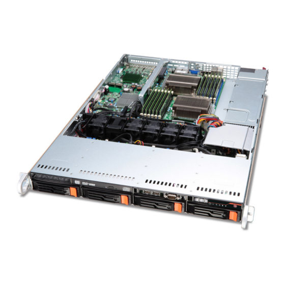
1 System tour System notes The AR160 is a high-end 1U server system with a dual CPU serverboard. The serverboard supports DDR3 memory, PCI Express 2.0, Flex I/O expansion, Trusted Platform Module (TPM) 1.2, and includes a host of server management tools. The server system accepts up to four hot- pluggable SATA drives, configurable for RAID 0, 1, 5 or 10. -
Page 19: External And Internal Structure
External and internal structure Front panel The illustration below shows the system front panel. Icon Component Optical drive USB 2.0 ports Serial port System ID indicator/ button LAN1 activity indicator LAN2 activity indicator Icon Component HDD activity indicator Power indicator Power button Hot-plug HDD activity indicator... - Page 20 Front panel LED indicator status LED indicator LED color Power indicator Green Green HDD activity Amber indicator System ID/Status/ Fault indicator Blue Blue LAN activity Green indicators Green (LAN1, LAN2) LED state Status S0: Power ON Blink (1Hz with S1: Sleep at 50% duty cycle) Blink...
-
Page 21: Rear Panel
Rear panel Component Power socket PS/2 mouse port Server management port (RJ-45) (10/100 Mbps) Low-profile PCI Express 2.0 x8 expansion slot Full-height PCI Express 2.0 x16 expansion slot Full-height PCI Express 2.0 x8 Flex I/O expansion slot System ID indicator Gigabit LAN ports (10/100/1000 Mbps) Monitor port COM port... -
Page 22: Lan Port Led Indicators
Rear panel LED indicator status LED indicator LED color System ID indicator Blue Blue LAN port LED indicators LED indicator LED color RJ45 LED (Left) Green Amber RJ45 LED (Right) Yellow Yellow LED state Status Normal System ID button pressed Blinking IPMI-activated system ID LED state... -
Page 23: Internal Components
Internal components Component Hard disk drives System fan modules Memory modules Air duct PCI riser board bracket assembly Mainboard Power supply module... -
Page 24: Mainboard
Mainboard The mainboard becomes accessible once you open the system. It should look like the figure shown below. Connector P1-DIMM3A, P1-DIMM3B, P1-DIMM2A, P1-DIMM2B, P1-DIMM1A, P1-DIMM1B CPU2 Description DDR3 sockets for processor 1 Processor 2 socket 1 System tour... - Page 25 Connector Description JPW3 8-pin processor power connector JPW2 8-pin processor power connector JPW1 20-pin ATX power connector Power supply SMBus I FAN1 Chassis fan 1 FAN2 Chassis fan 2 BATTERY CMOS battery FAN3 Chassis fan 3 P2-DIMM1B, DDR3 sockets for processor 2 P2-DIMM1A, P2-DIMM2B, P2-DIMM2A,...
- Page 26 Connector USB7 USB6 IPMB FAN6 COM2 SXB3 SXB1 CPU1 SXB2 UIOP LAN2 LAN1 COM1 IPMI LAN USB0/1 Description USB port 7 (Type A connector) USB port 6 (Type A connector) IPMB header (for an IPMI card) Chassis fan 6 Serial header PCI Express 2.0 x16 expansion slot (for riser card) PCI Express 2.0 x4 expansion slot (for riser card) Processor 1 socket...
-
Page 27: Mainboard Jumper Settings
Mainboard jumper settings Jumper Description ME Mode Select JPRST1 BMC/PHY Reset Enable/Disable JWD1 Enable/Disable/ Reset Watch Dog ME Recovery Default Setting Open (Normal). Allows you to reset the Baseboard Management Controller (BMC) chip and the PHY chip. Open (Normal) Close (Reset) Pins 1-2 (Reset). - Page 28 Jumper Description JBT1 Clear CMOS SMB to PCI-Exp. Slots SMB to PCI-Exp. Slots JPG1 Enable/Disable JPL1 Enable/Disable LAN1/2 Note: Jumpers not indicated are for test purposes only. 1 System tour Default Setting Instead of pins, this jumper consists of contact pads to prevent accidental clearing of the CMOS contents.
- Page 29 Mainboard LED connectors Description Onboard Standby PWR warning LED Indicator System ID LED Indicator...
- Page 30 1 System tour...
-
Page 31: System Setup
2 System setup... -
Page 32: Setting Up The System
Ensure you have the following items: • Acer AR160 system • Acer AR160 accessory box If any of the above items is damaged or missing, contact your dealer immediately. Save the boxes and packing materials for future use. 2 System setup... -
Page 33: Connecting Peripherals
Connecting peripherals Caution! The server operates on 100-127/200-240 VAC only. Do not connect the system to an incorrect voltage source. Refer to the illustration below for specific connection instructions on the peripherals you want to connect to the system. Front connections Rear connections Note: Consult the operating system manual for information on how to configure the network setup. -
Page 34: Turning On The System
Turning on the system After making sure that you have properly set up the system and connected all the required cables, you can now power on the system. To power on the system: After plugging in the power cord, press the power button. The system starts up and displays a welcome message on the monitor. -
Page 35: Power-On Problems
Power-on problems If the system does not boot after you have applied power, check the following factors that might have caused the boot failure. • The external power cord may be loosely connected. Check the power cord connection from the power source to the power supply module AC input connector on the rear panel. -
Page 36: Configuring The System Os
Configuring the system OS Acer Smart Setup assists you to conveniently install your choice of operating system. Note: To purchase the Acer Smart Server Manager software, contact your local representative. To start using Smart Setup, follow the steps below. Locate the Smart Setup included in the system package. -
Page 37: Turning Off The System
Turning off the system There are two ways to turn off the server — via software or via hardware. The software procedure below applies to a system running the Windows operating system. For further operating system shutdown procedures, refer to the related user documentation. To turn off the system via software: Press <Ctrl>... - Page 38 2 System setup...
-
Page 39: System Upgrades
3 System upgrades... -
Page 40: Installation Precautions
Installation precautions Before you install any server component, we recommend that you read the following sections. These sections contain important ESD precautions along with pre-installation and post-installation instructions. ESD precautions Electrostatic discharge (ESD) can damage the processor, disk drives, expansion boards, mainboard, memory modules and other server components. -
Page 41: Post-Installation Instructions
Place the system unit on a flat, stable surface. Open the system according to the instructions on page 33. Follow the ESD precautions described in this section when handling a server component. Post-installation instructions Perform the steps below after installing a server component. See to it that all components are installed according to the described step-by-step instructions. -
Page 42: Configuring The Storage Devices
Configuring the storage devices The system supports up to four 3.5-inch hot-plug SAS/SATA hard disk drives. An optional optical drive can also be added to the server. Accessing the drive bays Since SAS/SATA drives have hot-plug capability, you do not need to access the inside of the chassis or power down the system to install or replace SAS/SATA drives. -
Page 43: Removing And Installing A Hard Disk Drive
Determining drive status Each HDD carrier features two status LED indicators (see page 3) to display the hard drive status. If you are replacing a failed HDD, determine which drive has failed by checking the hot-plug HDD status indicators. Description Onboard SATA RAID HDD present no access HDD access... - Page 44 (3) Pull the lever and slide the carrier from the chassis. Observe the post-installation instructions described on page 25. Installing a hard disk drive with carrier Slide the HDD carrier all the way into the drive bay. Use the lever to push the HDD carrier until it locks into place, then close the HDD carrier lever.
-
Page 45: Removing And Installing An Optical Drive
Removing and installing an optical drive The system supports a slim SATA optical drive. Observe the ESD precautions described on page 24. Remove the top cover. See page 33. If an optical drive is present in the system, unplug the power and data cables from the drive. -
Page 46: Installing And Removing The Power Supply
Installing and removing the power supply WARNING! To reduce the risk of personal injury or damage to the equipment, the installation of power supply modules should be referred to individuals who are qualified to service server systems and are trained to deal with equipment capable of generating hazardous energy levels. -
Page 47: Power Supply Failure
If the power supply unit fails, the system will shut down and you will need to replace the power supply unit. Replacement units can be ordered directly from Acer. Replacing the power supply Press the main power button on the front of the chassis and then unplug the AC power cord to completely remove power from the system before removing the power supply. - Page 48 Push the new power supply module into the power bay until it clicks into place. Plug the AC power cord back into the module and power up the server by pushing the power on button. 3 System upgrades...
-
Page 49: Opening The Server
Opening the server Caution! Before you proceed, make sure that you have turned off the system and all peripherals connected to it. Read the “Pre- installation instructions” on page 24. You need to open the server before you can install additional components or access the system’s internal components. -
Page 50: Removing And Installing The Air Duct
Installing the top cover Perform the pre-installation instructions described on page 24. Install the top cover. (1) Place the top cover on the chassis so that the tabs on the cover align with the slots on the chassis. (2) Slide the top cover toward the front of the chassis until it is fully closed. -
Page 51: Replacing A System Fan
Place the air duct on the chassis so that the tabs on the air duct align with the slots on the chassis. Caution! Do not pinch or unplug cables that may be near or under the air duct. Replacing a system fan The system has five high-performance PWM fans to provide the cooling for the system. - Page 52 Remove the fan module. (1) Disconnect the fan cable. (2) Pull the fan up and away from the chassis. Install the new fan module. (1) Insert the new fan into the chassis. (2) Connect the fan cable. Check the routing of all cables for obstructions.
-
Page 53: Replacing The Processor And Heatsink
Observe the post-installation instructions described on page 25. Replacing the processor and heatsink Notes: • Always connect the power cord last and always remove it before adding, removing or changing any hardware components. Make sure that you install the processor into the CPU socket before you install the CPU heatsink. -
Page 54: Installing A Heatsink
Using a screwdriver, loosen the heatsink screws from the mainboard. Lift the heat sink away from the processor. Lay down the heat sink in an upright position — with the thermal patch facing upward. Do not let the thermal patch touch the work surface. - Page 55 Place the heatsink on top of the CPU so that the four mounting holes are aligned with those on the (preinstalled) heatsink retention mechanism. Screw in two diagonal screws (i.e. the #1 and the #2 screws) until just snug. Do not fully tighten the screws or you may damage the CPU.)
- Page 56 Add the two remaining screws then finish the installation by fully tightening all four screws. 3 System upgrades...
-
Page 57: Upgrading The Processor
Upgrading the processor Processor configuration guidelines The server supports two LGA 1366 processor sockets supporting dual- core or quad-core Intel Xeon processors. The supplied processors may be upgraded or additional processors installed. Observe the following guidelines when replacing or installing a processor. - Page 58 (4) Grasp the installed processor by its edges and lift it out of its socket. (5) Store the old processor inside an anti-static bag. Remove the new processor from its protective packaging. Install the new processor. (1) Hold the processor by its edges. Make sure the alignment tabs on the socket fit the two notch located on the edge of the processor.
- Page 59 (4) Engage the load lever back into place. Apply the thermal interface material. (1) Use an alcohol pad to wipe off the old thermal grease from both the heat sink and the processor socket retention plate. (2) Apply a thin layer of an approved thermal interface material before installing the heat sink.
-
Page 60: Upgrading The System Memory
Upgrading the system memory System memory interface Each processor has three memory channels (1, 2 and 3 ) and each channel has two slots - A (PxDIMM1A, 2A, 3A in blue) and B (PxDIMM1B, 2B, 3B in black). So, the system has a total of twelve memory slots. - Page 61 For dual processors • Populate DIMM slots 1A of each CPU first, followed by slots 2A, 3A,1B, 2B and 3B. • Install DIMM modules of the same type, size, and manufacturer in the same colored DIMM slots. Memory population for independent mode Single processor configuration Single processor Processor 1 P1DIMM slots...
-
Page 62: Mirroring Mode
Mirroring mode • For mirroring mode, the memory contains a primary image and a copy of the primary image. Therefore, the effective size of memory is reduced by at least one-half. • Channels 3 has no function and cannot be populated in this mode. •... - Page 63 Lockstep mode • In Lockstep Channel Mode, each memory access is a 128-bit data access that spans Channel 1 and Channel 2. This is done to support SDDC for DRAM devices with 8-bit wide data ports. The same address is used on both channels such that an address error on any channel is detectable by ECC.
- Page 64 4. The size of each DIMM must be the same across the configuration. 5. Do not mix UDIMMs with RDIMMs. Sparing mode (only supported on Intel Xeon Processor 5600 Series CPUs) • In this mode, if the system detects degrading memory and did not crash, the data in the failed channel will be copied to the spare channel.
- Page 65 Notes: 1. Place DIMMs in “X” location. 2. DIMM population must correspond to the above tables. 3. DIMM modules support 1 GB, 2 GB, 4 GB and 8 GB DIMMS. 4. The size of each DIMM must be the same across the configuration.
-
Page 66: Installing A Memory Module
Installing a memory module: Warning! Memory of the identical size, speed, and organization must be installed in the same colored DIMM slots. Locate the DIMM slot on the mainboard. Install the memory module. Align then insert the DIMM into the socket. Push the DIMM to the socket until the retaining clips snap inward. -
Page 67: Removing A Memory Module
Removing a memory module: Important: Before removing any DIMM from the mainboard, make sure to create a backup file of all important data. Remove the memory module. Press the holding clips on both sides of the DIMM slot outward to release the DIMM. Gently pull the DIMM upward to remove it from the DIMM slot. -
Page 68: Installing An Expansion Card
Installing an expansion card Your server has a preinstalled riser card designed specifically for use in the 1U rackmount chassis. Depending on the type of riser card installed, you can install the following expansion cards: • Left riser card (pre-installed) •... - Page 69 Insert the card. Slide the bolts back and secure the card with the screw.
-
Page 70: Installing The Right Riser Card And The Gigabit Dual Port Server Adapter
Connect the appropriate cables to the card (SAS card illustration shown below). Installing the right riser card and the Gigabit dual port server adapter Perform the following steps: Insert the right riser card into the PCI expansion slot. 3 System upgrades... - Page 71 Secure the riser card with two screws. Remove the screw that secures the PCI slot shield. Slide the shield lock away from the slots. Remove the PCI slot shield.
- Page 72 Insert the add-on card into the riser card. Slide the shield lock back. Secure the add-on card with the screw. Connect the appropriate cables to the card. 3 System upgrades...
-
Page 73: System Bios
4 System BIOS... -
Page 74: Introduction
When an option is selected in the left frame, it is highlighted in white. Often a text message will accompany Note: the BIOS has default text messages built in. Acer retains the option to include, omit or change any of these text messages. -
Page 75: Main Setup
Warning! Do not upgrade the BIOS unless your system has a BIOS- related issue. Flashing the wrong BIOS can cause irreparable damage to the system. In no event shall Acer be liable for direct, indirect, special, incidental, or consequential damages arising from a BIOS update. -
Page 76: System Memory
4 System BIOS entered in HH:MM:SS format. (Note: The time is in the 24-hour format. For example, 5:30 P.M. appears as 17:30:00.) BIOS Build Ver: This item displays the BIOS revision used in your system. BIOS Build Date: This item displays the date this BIOS was completed. Processor The BIOS will automatically display the status of the processor used in your system and indicate the CPU type used. -
Page 77: Advanced Settings
Advanced Settings Use the arrow keys to select Boot Setup and press <Enter> to access the submenu items: Boot Features Quick Boot: Skip certain tests during POST to reduce the time needed for system boot. Quiet Boot: Allows the bootup screen options to be modified between POST messages or the OEM logo. -
Page 78: Processor & Clock Options
Power Button Function: If set to Instant_Off, the system will power off immediately when you press the power button. If set to 4_Second_Override, the system will power off when you press the power button for four seconds or longer. Restore on AC Power Loss: Use this feature to set the power state after a power outage. - Page 79 Important: The following feature is only available if supported by the processor and/or operating system. Adjacent Cache Line Prefetch: The CPU fetches the cache line for 64 bytes if this option is set to Disabled. The CPU fetches both cache lines for 128 bytes as comprised if Enabled.
-
Page 80: Advanced Chipset Control
4 System BIOS Intel EIST Technology: EIST (Enhanced Intel SpeedStep Technology) allows the system to automatically adjust processor voltage and core frequency in an effort to reduce power consumption and heat dissipation. Please refer to Intel’s web site for detailed information. The options are Disable (Disable GV3) and Enable (Enable GV3). - Page 81 Important: The following feature is only available when QPI Links Speed is set to Full Speed. QPI Frequency: This selects the desired QPI frequency. QPI L0s and L1: This enables the QPI power state to low power. L0s and L1 are automatically selected by the motherboard. Memory Frequency: This feature enables you to force a DDR3 frequency slower than what the system has detected.
-
Page 82: Southbridge Configuration
• Temperature Rise - This is the temperature rise to the DIMM thermal zone. Steps are in 0.5 °C increments. The default is [020]. Press "+" or "-" on your keyboard to change this value. • Air Flow - This is the air flow speed to the DIMM modules. Each step is one mm/sec. - Page 83 Note: Only available when USB Functions is set to Disabled. Otherwise, this item will be set to Enabled by the BIOS. Legacy USB Support: Select Enabled to use Legacy USB devices. If set to Auto, legacy USB support will be automatically enabled if a legacy USB device is installed on the motherboard.
- Page 84 IDE Detect Timeout (sec): Use this feature to set the time-out value for the BIOS to detect the ATA, ATAPI devices installed in the system. Primary IDE Master/Slave, Secondary IDE Master/Slave, Third IDE Master, and Fourth IDE Master: These settings allow you to set the parameters of the IDE slots.
- Page 85 • DMA Mode Select Description Auto Automatically detect IDE DMA mode when the IDE disk drive support cannot be determined. SWDMA0 Use Single Word DMA mode 0. It has a data transfer rate of 2.1 MBs. SWDMA2 Use Single Word DMA mode 2. It has a data transfer rate of 8.3 MBs.
- Page 86 Plug & Play OS: Yes allows the OS to configure Plug & Play devices. (This is not required for system boot if your system has an oerating system that supports Plug & Play.) Select No to allow the BIOS to configure all devices in the system.
-
Page 87: Super Io Device Configuration
Load Onboard LAN1 Option ROM/Load Onboard LAN2 Option ROM: Select Enabled to enable the onboard LAN1 or LAN2 Option ROM. This is to boot computer using a network interface. Onboard LAN Option ROM Select: Select iSCSI to use the iSCSI Option ROM to boot the computing using a network device. - Page 88 Temperature Tolerance is, and not the other way around. This results in better CPU thermal management. Acer has leveraged this feature by assigning a temperature status to certain thermal conditions in the processor (Low, Medium and High). This makes it easier for you to understand the CPU’s temperature status, rather than by just simply seeing a temperature reading (i.e., 25...
-
Page 89: Acpi Configuration
User intervention: No action is required. However, consider checking the CPU fans and the chassis ventilation for blockage. • High – The processor is running hot. This is a caution level since the CPU’s Temperature Tolerance has been reached (or has been exceeded) and may activate an overheat alarm. -
Page 90: Trusted Computing
High Performance Event Timer: Select Enabled to activate the high- performance event timer to produce periodic interrupts at a much higher frequency than a real-time clock does when synchronizing multimedia streams, providing smooth playback and reducing the dependency on other timestamp calculation devices, such as an x86 RDTSC Instruction embedded in the CPU. -
Page 91: View Bmc System Event Log
• TPM Owner - Select Enable install to allow the TPM Owner to install devices/programs. Select Disable install to prevent the TPM Owner from installing devices/programs. Select Don't change to keep the current TPM Owner Privilege setting. Select Clear to remove the current TPM owner from the TPM Owner list. -
Page 92: Set Lan Configuration
Clear BMC System Event Log Clear BMC System Log: Select OK and press <Enter> to clear the BMC system log. Select Cancel to keep the BMC System log. Caution: Any cleared information is unrecoverable. Make absolutely sure that you no longer need any data stored in the log before clearing the BMC Event Log. -
Page 93: Security Settings
• Gateway Address - The BIOS will automatically display the Gateway address of this machine. This should be in decimal and in dotted quad form (i.e., 192.168.10.253). The value of each three- digit number separated by dots should not exceed 255. •... -
Page 94: System Management Settings
Change Supervisor Password: Select this feature and press <Enter> to access the submenu, and then type in a new Supervisor Password. User Access Level: (Available when Supervisor Password is set as above) Available options are • Full Access - grants full User read and write access to the Setup Utility. -
Page 95: System Information
System Information This submenu displays the following product information. • System Product Name • System Serial Number • Base Board Product Name • Base Board Serial Number • UUID • NIC1 Mac Address • NIC2 Mac Address • SDR Version •... -
Page 96: Remote Access Configuration
192.168.10.253). The value of each three-digit number separated by dots should not exceed 255. Note: This feature can be changed by the user when the IP Source is set to Static. Subnet Mask: This item displays the current subnet mask setting for your IPMI connection. -
Page 97: Event Log Configuration
Base Address, IRQ: This item displays the base address and IRQ of the serial port used for Console Redirection. Serial Port Mode: Allows you to set the serial port mode for Console Redirection. Flow Control: Allows you to set the flow control for Console Redirection. -
Page 98: Boot Settings
Mark All Events as Read: Marks all events as read. Clear Event Log: This option clears the Event Log memory of all messages. Boot Settings This submenu allows you to configure boot settings for the system. Boot Device Priority This feature allows you to specify the sequence of priority for the Boot Device. -
Page 99: Network Drives
Network Drives This feature allows you to specify the boot sequence from all available network drives. The settings are Disabled and a list of all network drives that have been detected. • 1st Drive • 2nd Drive • 3rd Drive Removable Drives This feature allows you to specify the boot sequence from all available removable drives. -
Page 100: Exit Options
4 System BIOS Exit Options Select the Exit tab from the BIOS Setup Utility screen to enter the Exit BIOS Setup screen. Save Changes and Exit: When you have completed the system configuration changes, select this option to leave the BIOS Setup Utility and reboot the computer, so the new system configuration parameters can take effect. -
Page 101: System Troubleshooting
5 System troubleshooting... -
Page 102: Resetting The System
Resetting the system Before going through in-depth troubleshooting, attempt first to reset the system using one of the methods below. To do this Soft boot reset to clear the system memory and reload the operating system. Cold boot reset. Turn the system power off and then on. -
Page 103: Bios Error Beep Codes
BIOS error beep codes During POST (Power-On Self-Test) routines, which are performed each time the system is powered on, errors may occur. Non-fatal errors are those, which, in most cases, allow the system to continue the boot-up process. The error messages normally appear on the screen. -
Page 104: Initial Troubleshooting Checklist
Initial troubleshooting checklist Use the checklist below to eliminate the possible cause for the problem you are encountering. • AC power available at the wall outlet? • Is the power supply module properly installed? • Is the system power cord properly plugged into the power supply module socket? and connected to a NEMA 5-15R outlet for 100- 120 V or a NEMA 6-15R outlet for 200-240 V? •... -
Page 105: Hardware Diagnostic Testing
Hardware diagnostic testing This section provides a more detailed approach to identifying a hardware problem and its source. Checking the boot-up status Caution! Before disconnecting any peripheral cables from the system, turn off the system and any external peripheral devices. Failure to do so can cause permanent damage to the system and/ or the peripheral device. -
Page 106: Verifying The Condition Of The Storage Devices
5 System troubleshooting Verifying the condition of the storage devices As POST determines the system configuration, it tests for the presence of each mass storage device installed in the system. As each device is checked, its activity indicator should turn on green briefly. Check the activity indicators for the hard drive(s), DVD-ROM drive, and any other device you may have installed. -
Page 107: Specific Problems And Corrective Actions
Specific problems and corrective actions Listed below are specific problems that may arise during the use of your server and their possible solutions. Power indicator does not light. Do the following: • Make sure the power supply module is properly installed. •... - Page 108 ODD (optical disk drive) activity indicator does not light. Do the following: • Make sure the ODD drive is properly connected to your system. • Check that drive is properly configured. ODD tray cannot be ejected. Insert the tip of a paperclip into the small hole on the ODD drive. Slowly pull the tray out from the drive until the tray is fully extended then remove the disc.
- Page 109 Newly installed memory modules are not detected. Do the following: • Make sure the memory modules specifications comply with the system requirements. • Make sure the memory modules have been populated according to the system guidelines. • Make sure the memory modules are properly installed on their mainboard slots.
- Page 110 System does not recognize all of the processors installed. Do the following: • Make sure the processor specifications comply with the system requirements. • Make sure the processor has been populated according to the system guidelines. • Make sure the processor is properly installed on their mainboard slots.
- Page 111 If you are using an add-in video controller card, do the following: Verify that the display monitor works using the onboard video controller. Verify that the add-in video controller card is fully seated in its slot. Reboot the system for the changes to take effect. If there are still no characters on the screen after you reboot the system, reboot it again.
- Page 112 5 System troubleshooting...
-
Page 113: Appendix A Server Management Tools
Appendix A Server management tools... -
Page 114: Server Management Overview
BIOS and firmware, set up BMC, and configure RAID for the system hard drivers. For detailed instructions on this utility, please refer to the Acer Smart Setup Help file. Note: BIOS and firmware updates are only available on selected operating systems. -
Page 115: Raid Configuration Utilities
RAID configuration utilities Intel onboard SATA RAID Creation Configuring Intel onboard SATA RAID This section briefly shows how to create RAID volume with Intel onboard SATA RAID. To enable the Intel onboard SATA RAID controller Turn on the server and the display monitor. If the server is already turned on, please close all open applications and then restart the server. -
Page 116: Adaptec Onboard Sata Raid Creation
Now that the RAID volume is created, you can press ESC or select option 5. Exit to exit. Assigning Hot Spare drive The Intel onboard SATA RAID Configuration Utility in POST does not provide the function to assign a hot spare driver. Please assign a hot spare driver with Intel onboard SATA RAID utility installed in the operating system. - Page 117 Select the desired hard drive disk and then press INS to add it in Selected Drives area. Press Enter to complete the selection. Select Array Type. Configure the array properties. Press Done when finish. Press Y when prompted by "Do you want to create an array? (Yes/ No):".
-
Page 118: External Sata Raid Creation
External SATA RAID Creation This section briefly shows how to create RAID with the following external SATA RAID board options: • 4-port 3GB/s SAS RAID Adapter • 8-port 3Gb/s SAS RAID Adapter (256MB) • 8-port 3Gb/s SAS RAID Flex I/O Adapter (256MB or 512MB) Starting the RAID Configuration Utility To start the RAID Configuration Utility, •... - Page 119 RAID Flex I/O Adapter). Select the RAID Level you want to use, create the logical volume by specify the size at Select Size and click on Accept to create the logical volume. For 8-port 3Gb/s SAS RAID Adapter or 8-port 3Gb/s SAS RAID Flex I/ O Adapter, click on Next after you create the logical volume.
- Page 120 Appendix A Server management tools...
-
Page 121: Appendix B Rack Mount Configuration
ack mount Appendix B R configuration... -
Page 122: Rack Installation Information
Rack installation information Rack installation precautions Follow the rack manufacturer's safety and installation instructions for proper rack installation. The following additional rack safety installation measures should be considered: • Anchor the equipment rack The equipment rack must be anchored to an unmovable suitable support to prevent the rack from falling over when one or more systems are fully extended out of the rack assembly. - Page 123 • Reduced airflow The amount of airflow required for the safe operation of the equipment should not be compromised when installing the system in a rack. • Mechanical loading Exercise care when mounting the system in a rack to avoid any accidents.
-
Page 124: System Rack Installation
Appendix B Rack mount configuration System rack installation The server should be mounted into a rack. A tool-less rack rail kit is available for installing system to a rack cabinet. The figure below shows the server in a rack-mount position. -
Page 125: Vertical Mounting Hole Pattern
Vertical mounting hole pattern The four vertical rails of the system rack contain mounting holes arranged in a manner shown in the figure below: The system occupies 1U in the rack. Count the U positions and hole numbers from the bottom up. The distance from the center of two holes with closer spacing to the center of the next pair is equivalent to 1U. -
Page 126: Installing The System Into The Rack
Installing the system into the rack Caution! To minimize the chances of injuries, make sure that two or more people help in installing the server. To install the system into a four-post rack Confi rm that the left and right inner rails have been correctly identified. - Page 127 Attach the inner rails to both sides of the server. Align the holes on the left and right front inner rails (1) to the hooks on the left and right sides of the server. Slide the rails to the front until the rails lock into place with an audible click.
- Page 128 Appendix B Rack mount configuration Align and insert the tabs on the left and right mounting rails to the rear rack post mounting holes (2).
- Page 129 Install the server into the rack. Insert the inner rails into the mounting rails, then push the server into the rack until you hear a click sound. Caution! To avoid personal injury, care should be taken when pressing the inner rail release latches and sliding the component into the rack.
- Page 130 For security purposes, you can use screws to secure the chassis handles to the front of the rack as illustrated below. Appendix B Rack mount configuration...
-
Page 131: Appendix C: Acer Smart Console
Appendix C: Acer Smart Console... -
Page 132: Using Acer Smart Console
Using Acer Smart Console Acer Smart Console has a user-friendly graphical user interface (GUI) and a standard Internet browser. This article will help you become familiar with the Acer Smart Console. Each function will be described clearly. Acer Smart Console offers:... -
Page 133: Accessing Acer Smart Console
Username: root • Password: superuser Click Login. The Acer Smart Console page appears. Note: The default username is root and the default password is superuser. Both the username and password are case sensitive and should be entered in lower case each time. -
Page 134: Acer Smart Console User Interface
Acer Smart Console user interface The Acer Smart Console page opens once you have logged in. This page provides a central location for managing all connected servers. The user interface includes a system status alert indicator, function list, menu bar, function title, section information. -
Page 135: Server Health
Server Health Displays data related to the server's health, such as sensor readings and the event log. This menu has two options: Sensor Readings and Event Log. Sensor Readings Allows you to monitor status of the voltages of the power supply, the fan speed, processor and system temperature sensors. -
Page 136: Event Log
Appendix C: Acer Smart Console destination, please go to Alert section. To refresh the sensor status, just click Refresh. Event Log Provides a record of system events related to critical hardware components. It logs the events when the sensor triggers an abnormal state or is recovering from an abnormal state. -
Page 137: Configuration
Configuration Allows you to designate email recipients for notification of system alerts, configure the Date and Time, configure the LDAP (Lightweight Directory Access Protocol) and RADIUS settings, configure the mouse mode settings, configure the network settings, configure the Dynamic DNS, configure the remote session settings, configure the SMTP email server settings, create an SSL certificate and manage users. - Page 138 Specify the event severity, such as Critical or Warning. Enter the IP information. Click Save. Setting up email notifications On the Alerts page click Modify. Specify the event severity, such as Critical or Warning. Enter the recipient's email address. Appendix C: Acer Smart Console...
-
Page 139: Date And Time
The Date and Time option allows you to set the BMC date and time. LDAP (if available) The LDAP option allows you to download the user account list and authentication from the LDAP server and create Acer Smart Console user accounts from this list. - Page 140 Enter the required information to access the LDAP server. Click Save. RADIUS The RADIUS option allows you to configure the RADIUS option. Configuring RADIUS On the RADIUS Settings page check Enable RADIUS. Enter the required information to access the RADIUS server. Click Save. Appendix C: Acer Smart Console...
-
Page 141: Mouse Mode
Mouse mode The Mouse mode option allows you to set a mouse mode to control your mouse. Setting the mouse mode Select a mouse mode from the Mouse Mode page. • Absolute: Select this setting when using a Microsoft Windows operating system. -
Page 142: Dynamic Dns
On the Network Settings page, select whether to obtain an IP address automatically or configure the network settings manually. Click Save. Dynamic DNS The Dynamic DNS option allows you to configure and change the management network parameters. Appendix C: Acer Smart Console... -
Page 143: Remote Session
Configuring Dynamic DNS On the Dynamic DNS Settings page, check Enable Dynamic DNS. Enter the required information to access the Dynamic DNS server. Click Save. Remote Session The following options allow you to enable or disable encryption on KVM or Media data during a redirection session. Select the remote session then press Save. - Page 144 On the SMTP Setting page, select a LAN channel number. Enter the IP address of the SMTP server. Enter the username and password. Enter the email address for sending email notifications. Enter the machine name. Click Save. Appendix C: Acer Smart Console...
- Page 145 SSL Upload The SSL Certificate option allows you to upload a SSL certificate manually. Uploading an SSL certificate On the SSL Upload page, click Browse to locate the SSL certificate on your system. Click Upload.
-
Page 146: User Privileges
No access: Users assigned this privilege have the least amount of system access. This is considered the lowest privilege level. • Operator: The operator privilege has restricted access. All BMC commands are allowed, except for the configuration commands Appendix C: Acer Smart Console... -
Page 147: Remote Control
that allows the user to change the behavior of the out-of-band interfaces. Operator privilege can not disable individual channels or change user access privileges. • Administrator: The administrator privilege has full access and can configure the software and add users. Administrator privilege have access to all BMC commands, including configuration commands for disabling a communication channel. -
Page 148: Server Power Control
Appendix C: Acer Smart Console KVM Remote Console Redirection The KVM Remote Console Redirection option allows you to start the KVM Remote Console utility and remotely manage the server using the monitor, mouse and keyboard as if you are connected directly to the server. -
Page 149: Launch Sol
Launch SOL SOL allows you to launch the remote console by using Serial over LAN. Click Launch SOL. Select the Baud rate from the pull-down menu as your SOL transfer rate. Make sure that the Baud rate selected here matches the Baud Rate set in the BIOS. Once you have selected the Baud rate, and press Start to start the session. -
Page 150: Virtual Media
Appendix C: Acer Smart Console Virtual Media Floppy disk This floppy disk option allows you to upload and share images via the BMC. These images will then be emulated to the host server as USB applications. Perform the floppy disk operation On the floppy disk page select an image file, then click Upload to upload your image file to the server. - Page 151 CD-ROM image This option allows you to upload and share images via the BMC. These images will then be emulated to the host server as USB applications. Perform the CD-ROM operation On the CD-ROM Setting page, enter the share host server. Enter the path to the CD-ROM image file.
-
Page 152: Maintenance
Maintenance Firmware Update Maintenance allows you to upgrade the BMC firmware (including Acer Smart Console and FRU information). Upgrading firmware On the Maintenance page click Enter Update Mode. The Firmware Upload page appears. Click Browse to locate the firmware image file. -
Page 153: Kvm Function Description
Snooping code for BIOS LPC Port80. KVM function description You can launch the KVM Remote Console utility from the Acer Smart Console Remote Control menu. The KVM Remote Console utility enables you to control any programs on the server remotely, using a local keyboard, monitor and mouse. - Page 154 Left Windows Key: This item performs the same function as pressing the <Left Windows> key. Right click this item to select Press Down or Press & Release for the <Left Windows> key function. • Macro: Click this item to activate a pull-down submenu displaying Appendix C: Acer Smart Console...
- Page 155 Macro hotkeys. • Macro Hotkeys: Click this item to display the macro hotkey pop-up submenu. The hotkeys include the following: • <Ctrl> + <Alt> + <Del> • <Alt> + <Tab> • <Alt> + <Esc> • <Ctrl> + <Esc> • <Alt> + <Space> •...
- Page 156 From the Preferences submenu, select Language settings. From the language settings pop-up menu select the language you want to use for console redirection. The language options are: English, Japanese, German, French, Spanish, Korean, and Italian. Appendix C: Acer Smart Console...
- Page 157 Once you have selected a language to use, click OK. Window From the Preference submenu, click Window to display the submenu. The Window pop-up menu will open. Check this box to allow the display window to be automatically resized for best video display. Click OK to keep the selection.
-
Page 158: User List
IP Address: This item displays the IP Address of the host server. Capture This feature allows you to capture the screen display on your remote console. Full Screen Capture: Click this item to capture the full screen video display. Appendix C: Acer Smart Console... -
Page 159: Exit
Exit Yes: At the prompt, click Yes to exit from remote redirection. No: Click No to return to the current session. - Page 160 Appendix C: Acer Smart Console...
-
Page 161: Index
Index Adaptec onboard SATA RAID configuring controller enabling creation Adaptec onboard SATA RAID Config- uration Utility entering air duct installing removing backplane board 2.5-inch HDD configuring the system OS controller Intel onboard SATA RAID front panel hard disk drive removing hard disk drive with carrier installing hard disk drives... - Page 162 opening the system installing the top cover removing the top cover optical drive removing PCI riser board bracket assembly peripherals population sequence lockstep configuration dual processor mirrored configuration single processor power cord Power supply module processor installing removing upgrade guidelines rack installing rack installation...