Table of Contents
Advertisement
Advertisement
Table of Contents
Troubleshooting

Related Manuals for Acer AR320 F2


Summary of Contents for Acer AR320 F2
- Page 1 Acer AR320F2 Service Guide PART NO.: PRINTED IN TAIWAN...
-
Page 2: Disclaimer
Preface This Service Guide provides you with all technical information relating to the BASIC CONFIGURATION decided for Acer's "global" product offering. To better fit local market requirements and enhance product competitiveness, your regional office MAY have decided to extend the functionality of a machine (e.g. add-on card, modem, or extra memory capability). -
Page 3: Conventions
Conventions The following conventions are used in this manual Denotes actual messages that appear Screen messages on screen. NOTE Gives bits and pieces of additional information related to the current topic. WARNING Alerts you to any damage that might result from doing or not doing specific actions. -
Page 4: Safety, Care And Regulatory Information
Safety, Care and Regulatory Information Before installing a server, be sure that you understand the following warnings and cautions. WARNING: To reduce the risk of electric shock or damage to the equipment: Do not disable the power cord grounding plug. The grounding plug is an important safety feature. Plug the power cord into a grounded (earthed) electrical outlet that is easily accessible at all times. -
Page 5: Table Of Contents
Table of Contents PREFACE REVISION HISTORY COPYRIGHT DISCLAIMER CONVENTIONS SAFETY, CARE AND REGULATORY INFORMATION PREVENTING ELECTROSTATIC DISCHARGE SERVER WARNINGS AND CAUTIONS TABLE OF CONTENTS MECHANICAL COMPONENTS SYSTEM COMPONENTS SYSTEM SPECIFICATIONS Hardware specification Environmental specification Mechanical specification Power supply specification APPEARANCE OF SYSTEM Front view Rear view Internal Component... - Page 6 LAN Port LED Description System Block Diagram MOTHERBOARD PLACEMENT AND JUMPER SETTING Motherboard Component Connector Description and Jumper Setting INSTALLING/REMOVING SYSTEM HARDWARE Chassis Cover Removal and Installation Removing the top cover CPU Installation / Removal Heat Sink Installation / Removal Memory Installation / Removal PCI Expansion Card Installation / Removal Install the expansion card...
- Page 7 Server Management Menu System Information Event Log Configuration Boot Options Menu Boot Manager Menu Exit Menu RAID CONFIGURATION UTILITIES Intel platform RAID configuration Set RAID Controller in Legacy Mode Enabling Intel Onboard SATA RAID Entering Intel onboard SATA RAID BIOS Utility Loading Factory Default Setting Creating a RAID Volume Initializing a RAID Volume...
- Page 8 Creating a RAID Volume Initializing a RAID Volume Assigning a Hot Spare Drive 3041E-R RAID configuration Set RAID Controller in Legacy Mode Entering RAID BIOS Utility Loading Factory Default Setting Creating a RAID Volume Initializing a RAID Volume Assigning a Hot Spare Drive TROUBLESHOOTING Error Symptoms List BMC Event and iKVM Event Troubleshooting...
-
Page 9: Mechanical Components
Mechanical Components Item Photo Part number Chassis HS.R8000. (With Fixed Power) HS.R8000. (With Redundant Power) Power PY.4000G. Supply (Fixed) Power PY.4000G. Supply (Redund ant) - Page 10 Mylar 47.R80S2. 42.R6J0L. Duct 42.R6J0L. Cage 50.R6J0L. Cable 700mm (M/B to front I/O board) SAS/SA CA.31400. TA signal mini SAS to mini cable (B/P to M/B or B/P to...
- Page 11 RAID card) SMBUS CA.31400. signal Cable (B/P to M/B) Cable 50.R6J0L. IDC 26P 490mm front LED/SW signal (M/B to front I/O board) Case 50.R310L. Open Cable Cable CA.R6J00. for slim SATA 390mm Front I/O 55.R6J0L. board...
- Page 12 Main MB.R800A Board .001 Hot plug TA.35400. hard drive back plane board Riser TA.R6J00. Card System HI.30900.0 fan kit (40*40*2 System HI.30900.0 fan kit (40*40*5 Hard TC.32900. Drive 005 (FXN) Carrier...
- Page 13 Hard TC.31300. Drive 010 (FXN) Dummy HI.30900.0 Heat Sink Slide TC.30800. Rail Kit TC.30800.
-
Page 15: System Components
System components Item Description Top cover Hard drive blank Main board System fans Power supply cage Heat sink System fan duct PCIe Riser Cage... -
Page 16: System Specifications
System Specifications Hardware specification System unit Item Description Processor socket Intel LGA1155 Intel Xeon E3-1200 series Processor Support TDP 95W Intel C204 PCH – north bridge, core logic controller Core logic chipsets Intel 82574L GbE controller LAN controller ... - Page 17 Memory Item Description Number of DIMM slots Four Maximum memory 32 GB (8 GB in each of the four DIMM slots) capacity Single DIMM, non-interleaving (DIMM 1A) Memory modes Two DIMMs, interleaving (DIMM 1A and DIMM 2A) Four DIMMs, full memory configuration Memory controller Integrated in CPU DIMM specifications...
- Page 18 Dual-Core Intel Core™ i3 Specification Description Processor Ci3-2130 Ci3-2100 number CPU speed 3.4GHz 3.1 GHz Bus speed External Clock Frequency External Clock Frequency (BLK) (BLK) 100MHz 100 MHz Bus/core ratio Core Max Ratio Limit 34 Core Max Ratio Limit 31 Core Min Ratio Limit 9 Core Min Ratio Limit 16 Intel Smart cache size...
- Page 19 Quad-Core Intel Xeon Specification Description Processor XE3-1280 XE3-1270 XE3-1240 XE3-1230 XE3-1225 XE3-1220 number CPU speed 3.5 GHz 3.4 GHz 3.3 GHz 3.2 GHz 3.1 GHz 3.1 GHz Bus speed External Clock External Clock External Clock External Clock External Clock External Clock Frequency Frequency Frequency...
-
Page 20: Environmental Specification
Environmental specification Item Description Temperature range Operating 5–35°C (41–95°F) Non-operating -20–60C (-4–140°F) Humidity (non-condensing) Operating 8-90% RH Non-operating 5-95% RH Acoustic noise SAS Mode (Idle) 43dBA / 5.6 BA SAS Mode (Operating) 49dBA / 6.1 BA SATA Mode (Idle) 40dBA / 5.1 BA SATA Mode (Operating) 44dBA / 5.7 BA * All temperature ratings shown are for sea level. -
Page 21: Mechanical Specification
Mechanical specification Item Description System board platform ATX (Advanced Technology Extended) System board dimensions Length 304.8mm Width 243.84mm System Dimensions Height 43.6 mm Depth 638mm Width 444mm Server weight (maximum configuration, approximate) Basic configuration (excluding the 12.7KG keyboard and mouse) Fully loaded configuration 10.3KG (including the keyboard, mouse,... -
Page 22: Power Supply Specification
Power supply specification AR320 F2 supports 400W power supply modules. For Fixed Power Supply Item Description Model DPS-400AB-12E Type 400W Dimensions Height 40.0 mm (1.57 in.) Depth 150 mm (5.9 in.) Width 81.5 mm (3.2 in.) Weight (approximate) 0.88kg (1.94 lb) - Page 23 For Redundant Power Supply Item Description Model DPS-500WB A+RPS-450-1 E Type 400W Dimensions Height 40.0 mm (1.57 in.) Depth 316.9 mm (12.47 in.) Width 96.8 mm (3.81 in.) Weight (approximate) 2.13kg (4.7 lb) Input requirements Rated input voltage 100–127 VAC/ 6.5A , 200–240 VAC/ 3.0A Normal line voltage 115 VAC, 230 VAC Line frequency...
-
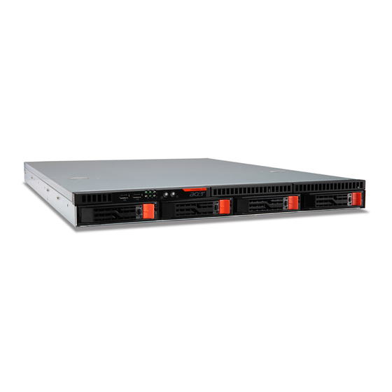
Page 24: Appearance Of System
Appearance of System Front view Item Icon Component Description Connects to USB devices. USB 2.0 Ports HDD activity indicator Indicates the status of a system hard drive. Power indicator Indicates the system power status. LAN1 activity indicator Indicates the system network 1 connection status. LAN2 activity indicator Indicates the system network 2 connection status. -
Page 25: Rear View
Rear view Item Icon Component Description Power supply module cord Connect the system power cord here. socket PSU fan PSU FAN Regulate PSU airflow. Serial port Connects to serial devices. Monitor port Connects to monitors. 10/100/1000M LAN port 1/2 Connects to an Internet or intranet network. USB 2.0 ports Connects to USB devices. -
Page 26: Internal Component
Internal Component Item Description Power module bay Fan duct PCIe slot cage System fans Release sliders for the HDD cages. Release sliders for the ODD cages. -
Page 27: Switch And Led Indicators Introduction
Switch and LED Indicators Introduction This section discusses the different LED indicators located on the : Front panel Hot-plug HDD carrier LAN port Knowing what each LED indicator signifies can aid in problem diagnosis and troubleshooting. Front Panel LED Description Number Color Status... -
Page 28: Hard Disk Drive Sequence & Led Description
Hard Disk Drive Sequence & LED Description A drive activity LED indicator is mounted on the hot-plug HDD carrier. The table below lists the possible drive states. Status Green Amber Description HDD access Blinking Ongoing hot-plug HDD activity HDD failure Hot-plug HDD failure HDD rebuild Blinking... -
Page 29: System Block Diagram
System Block Diagram... -
Page 30: Motherboard Placement And Jumper Setting
Motherboard Placement and Jumper Setting Motherboard Component This section provides general information on changing jumper settings as well as specific jumper configuration for individual boards in the system. -
Page 31: Connector Description And Jumper Setting
Connector Description and Jumper Setting Item Code Description Item Code Description System ID button USB_LANM 10/100 LAN port for sever management intranet network.(top) USB ports. (bottom) USB_LAN2 LAN2 port/Share NIC (top), USB_LAN1 LAN1 port (top), USB ports USB ports (bottom) (bottom) COM1_VGA Serial port (top), VGA port... - Page 32 USB2 Front USB2 cable connector Intel C204 PCH chipset BIOS_RCVR BIOS recovery jumper USB1 Front USB 1 cable connector 1-2 Close: Normal operation. (Default) 2-3 Close: BIOS recovery mode. Battery COM2 Connects to serial port BMC_ROM1 BMC ROM PCI16X PCI-E x16 slot BMC controller...
-
Page 33: Installing/Removing System Hardware
This chapter contains step-by-step procedures on how to disassemble the server system for maintenance and troubleshooting. To disassemble the Acer AR320 F2 Server, please pay attention to each section’s instruction and tools needed. NOTE: The screws for the different components vary in size. During the disassembly process, group the... -
Page 34: Chassis Cover Removal And Installation
Chassis Cover Removal and Installation Removing the top cover Press the top cover release button located oh the edge of server. Slide the top cover toward the rear of the chassis to disengage it. -
Page 35: Cpu Installation / Removal
CPU Installation / Removal The mainboard supports one LGA1155 processor socket supporting Dual-Core Intel Xeon processor. You have the option to upgrade the default processor. Observe the following guidelines when replacing a processor. Before removing a processor, make sure to back up all important system files. •... -
Page 36: Heat Sink Installation / Removal
Heat Sink Installation / Removal Use a long-nosed screwdriver to loosen the four heat sink screws. Lift the heat sink away from the mainboard. Lay down the heat sink in an upright position - with the thermal patch facing upward. Do not let the thermal patch touch the work surface. -
Page 37: Memory Installation / Removal
Memory Installation / Removal The motherboard supports DDR3 memory modules, whereby BIOS will automatically detect memory capacity and specifications. Memory modules are designed so that they can be inserted only in one direction. The memory capacity used can differ with each slot. Installation step: Insert the DIMM memory module vertically into the DIMM slot, and push it down. -
Page 38: Pci Expansion Card Installation / Removal
PCI Expansion Card Installation / Removal Acer AR320 F2 has one bus slots with of two separate bus segments: PCI16X - PCI-E x16 slot Install the expansion card Lift the riser bracket slightly, then pull it out from the server chassis. -
Page 39: Hard Disk Drive Installation / Removal
Hard Disk Drive Installation / Removal Below is the instruction of HDD installation and removal SOP. Press the release button Pull the blank out of the drive bay. Slide hard disk into blank. Secure the HDD with four screws. Make sure the HDD is seated securely in the HDD blank. Connect the necessary power cable. -
Page 40: Power Supply Installation / Removal
Power supply installation / Removal The AR320 F2 supports 400 watts power supply modules. The system ships out with only one power supply module installed. Install a hot-swap power supply module Remove the four securing screws. Slide toward and lift to remove the power supply module from the system. -
Page 41: System Fan Installation / Removal
System Fan Installation / Removal Follow these instructions to remove and install the system fan: Disconnect all necessary cable connections. Lift the system fan out of the system. Reverse the step above to install the system fan. Below illustrated is the location of system fan. Please follow the below instruction to connect the respective system fan cable. - Page 42 System Fan Cable Corresponding Location: Cable Color Connect to FAN1 Black/Red/Yellow/Brown FAN_1A FAN3 (CN1) Black/Red/Yellow/Brown FAN_3A FAN3 (CN2) Grey/Red/Black/White FAN_3B FAN4 (CN1) Black/Red/Yellow/Brown FAN_4A FAN4 (CN2) Grey/Red/Black/White FAN_4B FAN5 Black/Red/Yellow/Brown FAN_5A FAN6 Black/Red/Yellow/Brown FAN_6A System Fan Cable Color and Pin Definition:...
-
Page 43: Cable Routing
Cable Routing Cable Routing image Suggest Cable Suggest Cable SAS Cable (8708EM2) Power cable USB cable Front panel board cable SATA cable (onboard SATA to ODD) SMBus cable Case open intrusion cable System fan cable... -
Page 44: Bios Setup
BIOS Setup System BIOS BIOS setup is a hardware configuration program built into the system’s Basic Input/Output System (BIOS). Since most systems are already properly configured and optimized, there is no need to run this utility. You will need to run this utility under the following conditions. When changing the system configuration settings •... -
Page 45: Server Management
Entering BIOS Setup Turn on the server and the monitor. If the server is already turned on, close all open applications, then restart the server. During POST, press F2 If you fail to press F2 before POST is completed, you will need to restart the server. The Setup Main menu will be displayed showing the Setup’s menu bar. -
Page 46: Main Menu
Main Menu Parameter Description Option System BIOS Display system BIOS version and build Version date. Build Date Processor Technical specifications for the installed CPU Type Core Frequency Count processor. Memory Total size of system memory detected Size during POST System Date Set the date following the weekday-month-day- year format. -
Page 47: Advanced Menu
Advanced Menu The Advanced menu display submenu options for configuring the function of various hardware components. Select a submenu item, then press Enter to access the related submenu screen. -
Page 48: Processor Configuration
Processor Configuration Parameter Description Option Intel Hyper Threading The Intel Hyper Threading Technology allows a single Enabled Technology processor to execute two or more separate threads Disabled concurrently. When hyper-threading is enabled, multi-threaded software applications can execute their threads, thereby improving performance. Active Processor Cores Setting the active processor core. - Page 49 P-State Coordination In HW_ALL mode, the processor hardware is HW_ALL responsible for coordinating the P-state among logical SW_ALL processors dependencies. The OS is responsible for SW_ANY keeping the P-state request up to date on all logical processors. In SW_ALL mode, the OS Power Manager is responsible for coordinating the P-state among logical processors with dependencies and must initiate the transition on all of those Logical Processors.
-
Page 50: Memory Configuration
Memory Configuration Parameter Description Option Total Memory Total size of system memory detected during POST DIMM Information The size of memory installed on each of the DDR3 #1A/1B/2A/2B Status slots. Memory Retest Select whether to delete the historical memory data log. -
Page 51: Chipset Configuration
Chipset Configuration Parameter Description Option Intel VT-d Technology Enable/Disable Intel VD-d Technology function. Enabled Disabled Intel TXT Technology Enable/Disable Intel TXT Technology function. Enabled Disabled ME Subsystem Press [Enter] for advanced configuration. Configuration ME Subsystem Enable/Disable ME Subsystem function. Enabled Disabled... -
Page 52: Acpi Settings
ACPI Settings Parameter Description Option HPET Support Enable/Disable HPET Support. Enabled (High Precision Event Disabled Timer) WHEA Support Enable/Disable WHEA Support. Enabled (Windows Hardware Error Disabled Architecture) -
Page 53: Sata/Sas Configuration
SATA/SAS Configuration... - Page 54 Parameter Description Option SATA Controller When enabled, the SATA controller will Enabled function normally. Disabled SATA Mode When set to IDE, the SATA controller disables its RAID and AHCI functions and RAID runs in the IDE emulation mode. You won't ACHI have access to the RAID setup utility.
-
Page 55: Pci Configuration
PCI Configuration Parameter Description Option PERR# Generation Enable/Disable PERR Generation. Enabled Disabled SERR# Generation Enable/Disable SERR Generation. Enabled Disabled PCI Express Slot #1 I/O ROM When enabled, This setting will initialize the Enabled device expansion ROM for the related PCI-E Disabled slot. -
Page 56: Usb Configuration
USB Configuration Parameter Description Option Detected USB Devices Displays the information of installed USB devices in the system. USB Controller When enabled, the USB controller Enabled will function normally. Disabled Legacy USB Support Enables or disables support for Enabled legacy USB devices. Disabled Port 60/64 Emulation Enable I/O port 60h/64h emulation... -
Page 57: Legacy Device Configuration
Legacy Device Configuration Parameter Description Option Serial Port 1/2 When enabled allows you to Enabled configure the serial port settings. Disabled When set to Disabled, displays no configuration for the serial port. Device Settings Displays Serial Port 1/2 device setting information Change Settings Change Serial Port 1/2 device Auto... -
Page 58: Power Configuration
Power Configuration Parameter Description Option Deep Power Off Mode Enable or Disable Deep Power Off Enabled Mode. Disabled Power On by RTC Alarm Select whether to wake up the Enabled system when an RTC alarm is Disabled detected. Restore on AC Power Loss Defines the power state to resume Last State to after a sys- tem shutdown that is... -
Page 59: Console Redirection
Console Redirection Parameter Description Option Console Redirection Select whether to enable console Serial Port 1 redirection. Console redirection Serial Port 2 enables users to manage the Disabled system from a remote location. Terminal Type Select a terminal type to be used for VT100 console redirection. - Page 60 control uses two wires to send start/stop signals. Recorder Mode When this mode enabled, only text Enabled will be send. This is to capture Disabled Terminal data. Resolution 100x31 Enables or disables extended Enabled terminal resolution. Disabled Legacy OS Redirection Resolution On Legacy OS, the number of Rows 80x24 and Columns supported redirection.
-
Page 61: Security Menu
Security Menu The Security menu allows you to safeguard and protect the system from unauthorized use by setting up access passwords. There are three types of passwords that you can set: Administrator password • Entering this password will allow the user to access and change all settings in the Setup Utility. User password •... - Page 62 TPM State Select Enabled to activate TPM State Enabled function. Disabled TPM Operation Schedule TPM operation. None Enable Take Ownership Disable Ownership Current TPM Status Display current TPM status information. Information...
-
Page 63: Setting A System Password
Setting a System Password Use the up/down keys to select a password parameter (Set Administrator Password or Set User Password), then press Enter. A password box will appear. Type a password then press Enter. The password may consist of up to eight alphanumeric characters (A-Z, a-z, 0-9). Retype the password to verify the first entry then press Enter again. -
Page 64: Server Management Menu
Server Management Menu Parameter Description Option System Information Displays basic system ID information, as well as BIOS version. Press Enter to access the related submenu. Event Log Configuration Displays Event Log advanced settings. Press Enter to access the related submenu. -
Page 65: System Information
System Information The System Information submenu is a simple display page for basic system ID information, Firmware version, and LAN settings. Parameter Description Option IPMI LAN Selection Determine the network settings. Dedicated When set to Dedicate Mode, you can Shared configure the BMC related settings through Failover the BMC port. -
Page 66: Event Log Configuration
Event Log Configuration... - Page 67 Parameter Description Option Change Smbios Event Press Enter to access the related submenu. Configuration View Smbios Event Log Displays Smbios Event Log . Press Enter to View Smbios Event Log View System Event Log Displays Systems Event Log . Press Enter to View System Event Log Erase Event Log Choose options for erasing Smbios Event Log Erasing is done prior to any logging activation...
-
Page 68: Boot Options Menu
Boot Options Menu The Boot Options menu allows you to set the drive priority during system boot-up. BIOS setup will display an error message if the drive(s) specified is not bootable. By default, the server searches for boot devices in the following order: Hard drive Optical disk drive Removable device... -
Page 69: Boot Manager Menu
Boot Manager Menu The Boot manager menu allows you to specify the boot-up drive. BIOS setup will display an error message if the drive(s) specified is not bootable. Parameter Description Option Built-in EFI Shell Press Enter to boot to Built-in EFI Shell. IBA GE Slot 00CB v1365 Press Enter to configure the device as the boot-up drive. -
Page 70: Exit Menu
Exit Menu The Exit menu displays the various options to quit from the BIOS setup. Highlight any of the exit options then press Enter. Parameter Description Option Save Changes and Exit Saves changes made and close the BIOS setup. Cancel Discard Changes and Exit Discards changes made and close the BIOS setup. -
Page 71: Raid Configuration Utilities
RAID Configuration Utilities Note: RAID supports various by models, please refer to the system specifications or installation and configuration guide for more detailed information. Intel platform RAID configuration Set RAID Controller in Legacy Mode NOTE. Currently, Intel onboard SATA RAID only supports Legacy mode. Please change PCI ROM Priority setting from EFI Compatible ROM to Legacy ROM in BIOS Setup. -
Page 72: Creating A Raid Volume
Creating a RAID Volume Select Create RAID Volume. The CREATE VOLUME MENU displayed. Type in the name of RAID volume. Select RAID 5 level. Select desired HDD to create the RAID. Select Create Volume. Press Y when “Are you sure you want to create the volume? (Y/N):” displayed. Now the RAID volume is created, you can press ESC and select Exit to exit. -
Page 73: Entering Lsi Onboard Sata Raid Bios Utility
SATA Mode [AHCI Mode] Please change SATA Mode from AHCI Mode to RAID Mode SATA Mode [RAID Mode] Please change SATA SW RAID Option Mode from Intel RAID to LSI RAID SATA SW RAID Option [LSI RAID] Please press F10 to save the setting before exit from BIOS Setup. Entering LSI onboard SATA RAID BIOS Utility Please press Ctrl-M when you see the RAID BIOS during POST. -
Page 74: Assigning A Hot Spare Drive
Select Initialize from Management menu. All logical drives should be listed under Logical Drives. Press <Spacebar> to select drives for initialization. The selected drive will be shown in yellow. After selecting the drives, press <F10> and select YES to start the initialization process. -
Page 75: Entering Raid Efi Utility (Efi Mode)
Adapter Selection page will show on the screen. Please click on Start to launch the configuration menu. Entering RAID EFI Utility (EFI Mode) Please enter EFI shell during POST. In EFI Shell, please type in drvcfg –s. You will see below options. Press 1 for EFI WebBIOS 2 for EFI CLI or any other key to return:... -
Page 76: Assigning A Hot Spare Drive
You will see all the logical drives listed. Click on Home to go back to the configuration menu. Assigning a Hot Spare Drive Select a free disk marked as UNCONF GOOD and listed under Physical Drives. Select Make Global HSP or Make Dedicated HSP options and then click on Go. Click on Home to go back to the configuration menu. -
Page 77: Initializing A Raid Volume
Initializing a RAID Volume After you create the array by pressing <C>, it initializes the RAID Volume automatically. Assigning a Hot Spare Drive Select SAS3041E and press <Enter>. Select RAID Properties and press <Enter>. Select View Existing Array and press <Enter>. Select Manage Array and press <Enter>. -
Page 78: Troubleshooting
Troubleshooting Error Symptoms List NOTE: To diagnose a problem, first find the error symptom in the left column. If directed to a check procedure, replace the FRU indicated in the check procedure. If no check procedure is indicated, the first Action/FRU listed in right column is the most likely cause. Error Symptom Action/FRU Processor / Processor Fan... - Page 79 Hard disk drive has write error. Enter BIOS Setup and Load default settings. Hard disk drive. Hard disk drive LED fails to light, but With the system power on, measure the voltage system operates normally. of hard disk LED connector. Hard drive LED cable.
- Page 80 Main board Parallel/Serial Ports Execute “Load BIOS Default Settings” in BIOS Setup to confirm ports presence before diagnosing any parallel/serial ports problems. Serial or parallel port loop-back test failed. Make sure that the LPT# or COM# you test is the same as the setting in BIOS Setup. Loop-back.
-
Page 81: Bmc Event And Ikvm Event Troubleshooting
BMC Event and iKVM Event Troubleshooting Sensor Name Troubleshooting CPU_Temp CPU temperature is overheating, please check the CPU temperature status and the CPU cooler is seated firmly. Shut down system if necessary. SYS Temp System temperature is overheating, please check the system temperature status and the system cooler is seated firmly. - Page 82 BP_FAN_3A The BP fan speed is too slow, please check the specified BP fan if the fan works functionally. BP_FAN_3B The BP fan speed is too slow, please check the specified BP fan if the fan works functionally. BP_FAN_4A The BP fan speed is too slow, please check the specified BP fan if the fan works functionally.
-
Page 83: Bios Beep Codes
BIOS Beep Codes BIOS Beep Codes Table PEI Beep Codes # of Beeps Description Memory not Installed. Memory was installed twice (InstallPeiMemory routine in PEI Core called twice) Recovery started DXEIPL was not found DXE Core Firmware Volume was not found Recovery failed S3 Resume failed Reset PPI is not available... -
Page 84: Bios Recovery Instruction
BIOS Recovery Instruction AMI has an embedded recovery technique. In the event that the BIOS becomes corrupt the boot block can be used to restore the BIOS to a working state. To restore your BIOS, please follow the instructions listed below: Recovery Instruction: 1. - Page 85 6. BIOS update.
-
Page 86: Bios Post Error Messages List
BIOS POST Error Messages List BIOS POST error message list PEI Phase Status Code Description Progress Code 0x10 PEI Core is started 0x11 Pre-memory CPU initialization is started 0x12 Pre-memory CPU initialization (CPU module specific) 0x13 Pre-memory CPU initialization (CPU module specific) 0x14 Pre-memory CPU initialization (CPU module specific) 0x15... -
Page 87: Dxe Phase
0x5A Internal CPU error 0x5B Reset PPI is not available 0x5C-0x5F Reserved for future AMI error codes S3 Resume Progress Codes 0xE1=0 S3 Resume is stared (S3 Resume PPI is called by the DXE IPL) 0xE1 S3 Boot Script execution 0xE2 Video repost 0xE3... - Page 88 0x7A – 0x7F Reserved for future AMI DXE codes 0x80 – 0x8F OEM DXE initialization codes 0x90 Boot Device Selection (BDS) phase is started 0x91 Driver connecting is started 0x92 PCI Bus initialization is started 0x93 PCI Bus Hot Plug Controller Initialization 0x94 PCI Bus Enumeration 0x95...
-
Page 89: Undetermined Problems
Undetermined Problems If an error message is present, go to “POST Error Messages List” on page 64. If you did not receive any messages, if the symptom is listed in “or “Error Symptoms List” on page 60. If you still cannot solve the problem, continue with this check: 1.