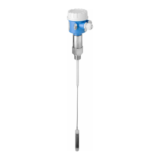
Endress+Hauser Liquicap M FMI52 HART Brief Operating Instructions
Capacitive continuous level measurement for liquids
Hide thumbs
Also See for Liquicap M FMI52 HART:
- Operating instructions manual (52 pages) ,
- Operating instructions manual (58 pages) ,
- Operating instructions manual (56 pages)

Related Manuals for Endress+Hauser Liquicap M FMI52 HART


Summary of Contents for Endress+Hauser Liquicap M FMI52 HART
- Page 1 Products Solutions Services KA01454F/00/EN/02.21 71510166 2021-02-01 Brief Operating Instructions Liquicap M FMI52 HART Capacitive Continuous level measurement for liquids...
-
Page 2: Table Of Contents
Table of contents Liquicap M FMI52 HART Table of contents About this document ............. . 2 Document conventions . - Page 3 Liquicap M FMI52 HART About this document NOTICE This symbol contains information on procedures and other facts which do not result in personal injury. 1.1.2 Electrical symbols Alternating current Direct current and alternating current Direct current Ground connection A grounded terminal which, as far as the operator is concerned, is grounded via a grounding system.
- Page 4 About this document Liquicap M FMI52 HART Tip Indicates additional information Reference to documentation Reference to page Reference to graphic Notice or individual step to be observed Series of steps Result of a step Help in the event of a problem...
-
Page 5: Basic Safety Instructions
It meets general safety standards and legal requirements. It is compliant with the EC directives listed in the device-specific EC Declaration of Conformity. Endress+Hauser confirms this by affixing the CE mark to the device. Incoming acceptance and product identification Incoming acceptance Check whether the packaging or content is damaged. -
Page 6: Product Identification
• the serial number on the nameplate into the Endress+Hauser Operations App or use the Endress+Hauser Operations App to scan the 2-D matrix code (QR Code) on the nameplate Order Code.:... -
Page 7: Mounting
Liquicap M FMI52 HART Mounting Mounting Mounting requirements 4.1.1 Mounting the sensor The Liquicap M FMI52 can be installed vertically from above. Make sure that: • the probe is not installed in the area of the filling curtain • the probe is not in contact with the container wall •... - Page 8 Mounting Liquicap M FMI52 HART 100% ≥ 500 (19.7) A0040579 Unit of measurement mm (in) Measuring range Inactive length When installing in a nozzle, use inactive length L3. The 0 % and 100 % calibration can be inverted. 4.1.3 Installation examples Rope probes The probe can be installed from above in conductive tanks made from metal.
- Page 9 Liquicap M FMI52 HART Mounting The following application examples show the vertical installation for continuous level measurement. A0040451 2 Rope probe A0040452 3 A probe with inactive length for the insulated tanks Endress+Hauser...
- Page 10 Mounting Liquicap M FMI52 HART A0040453 4 A probe with fully insulated inactive length for mounting nozzles Shortening the rope For information about the shortening kit, see Brief Operating Instructions KA061F/00. Tensioning weight with tension The end of the probe needs to be secured if the probe would otherwise touch the silo wall or another part in the tank.
-
Page 11: Probe With Separate Housing
Liquicap M FMI52 HART Mounting Probe with separate housing L4 ≤ 6m (20 ) A0040473 5 Connection of the probe and separate housing Explosive zone 1 Explosive zone 0 Rope length: max 9.7 m (32 ft) Cable length: max. 6 m (20 ft) The maximum cable length L4 and rope length L1 cannot exceed 10 m (33 ft). - Page 12 Mounting Liquicap M FMI52 HART r ≥ 100 (3.94) 61 (2.4) 75 (2.95) r ≥ 100 (3.94) A0040471 6 Housing side: wall mounting, pipe mounting, and sensor side. Unit of measurement mm (in) Values of parameters Polyester housing (F16) •...
- Page 13 Liquicap M FMI52 HART Mounting D and H5 parameter • rope probe without fully insulated inactive length and threads G¾", G1", NPT¾", NPT1", Clamp 1", Clamp 1½", Universal ⌀44 mm (1.73 in), flange < DN50, ANSI 2", 10K50: • D: 38 mm (1.5 in) •...
- Page 14 Mounting Liquicap M FMI52 HART 4.2.3 Wall mounting 1 → 2 → A0042318 A0042319 A0042320 ‣ ‣ ‣ Screw together the wall bracket Mark the distance between the Screw the separate housing on on the tube. holes on the wall before drilling.
- Page 15 Liquicap M FMI52 HART Mounting If the cable connection has to be shortened or led through a wall, it must be separated from the process connection. Disconnecting the connection cable Make sure that the connecting cable and the probe is not turning with the pressing screw.
- Page 16 Mounting Liquicap M FMI52 HART 7 → 8 → A0042117 A0042118 A0042119 ‣ ‣ ‣ Remove the blade plug from the Loosen the screw to disconnect Loosen the nut (M4) of the blade socket. the yellow and yellow-green plug. cables.
-
Page 17: Post-Installation Check
Liquicap M FMI52 HART Mounting gn/ye A0040734 7 Cable connections External screening (not required) Strand black (bk) (not required) Coaxial cable with central core and screening Solder the red (rd) strand with the central core of the coaxial cable (probe) -
Page 18: Electrical Connection
Electrical connection Liquicap M FMI52 HART Electrical connection Before connecting the power supply, note the following: • the supply voltage must match the data specified on the nameplate • switch off the supply voltage before connecting the device • connect the potential equalization to the ground terminal on the sensor When using the probe in hazardous areas, the relevant national standards and the information in the safety instructions (XA) must be observed. - Page 19 Liquicap M FMI52 HART Electrical connection A0040478 Cable entry Electronic insert connections: cable size max. 2.5 mm (14 AWG) The ground connection outside the housing, cable size max. 4 mm (12 AWG) ⌀d Cable diameter Cable entries • Nickel-plated brass: ⌀d = 7 to 10.5 mm (0.28 to 0.41 in) •...
-
Page 20: Wiring And Connecting
Electrical connection Liquicap M FMI52 HART • 12.0 to 36.0 V in the non-hazardous area • 12.0 to 30.0 V in the Ex ia hazardous area • 14.4 to 30.0 V in the Ex d hazardous area Wiring and connecting 5.2.1... - Page 21 Liquicap M FMI52 HART Electrical connection Release the cable gland. Insert the cable. Connecting the electronic insert to the power supply mounted in the housing T13: A0040637 Unscrew the housing cover. Remove the housing cover. Release the cable gland. Insert the cable.
- Page 22 Electrical connection Liquicap M FMI52 HART – A0040479 Supply voltage, communication resistor 250 Ω Commubox FXA195 Grounding terminal Endress+Hauser...
-
Page 23: Post-Connection Check
Liquicap M FMI52 HART Operation options 5.2.3 Connecting HART with other supply units A0040750 8 Remote control via HART protocol Transmitter power supply unit e.g. RN221N with communication resistor Connection output for Commubox FXA191, FXA195 Computer with control software (DeviceCare or FieldCare, AMS Device Manager, SIMATIC PDM) - Page 24 Operation options Liquicap M FMI52 HART • the operating elements at the FEI50H electronic insert • the display and operating module • the HART protocol with Commubox FXA195 and FieldCare operating program • the HART handheld terminal DXR375 6.1.1 Display and operating elements at the FEI50H electronic insert 4...20mA...
- Page 25 Liquicap M FMI52 HART Operation options • 5: Measuring range: select the measuring range in pF for: - measuring range probe length < 6 m (20 ft) corresponds to 2 000 pF - measuring range probe length > 6 m (20 ft) corresponds to 4 000 pF •...
- Page 26 Operation options Liquicap M FMI52 HART 6.1.2 Operation via the optional display and operating module Display and operating elements A0040480 10 Display and operating elements Menu title Item code of a displayed function Key symbols Hardware keys Symbols on the display Operating mode of the device •...
- Page 27 Liquicap M FMI52 HART Operation options A0032709 Due to editing a function: exits the editing mode for the current function Due to navigating: returns to the next-highest menu level Increase contrast A0032710 Increases the contrast of the display module Decrease contrast...
-
Page 28: Operation Via Fieldcare Device Setup
6.2.1 Function scope FDT-based plant asset management tool from Endress+Hauser. It can configure all smart field devices in a system and helps you manage them. By using the status information, it is also a simple but effective way of checking their status and condition. - Page 32 *71510166* 71510166 www.addresses.endress.com...