Table of Contents
Advertisement
Quick Links
Item #122135, 122855
Model # YG204-BN, YG204-TB
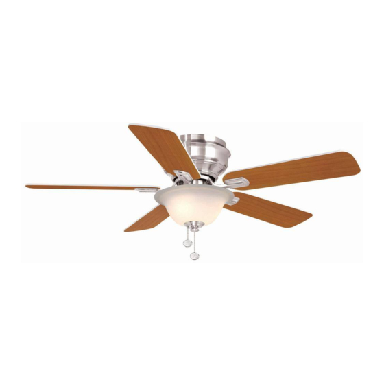
USE AND CARE GUIDE
HAWKINS 44 IN. CEILING FAN
Questions, problems, missing parts? Before returning to the store,
call Hampton Bay Customer Service
8 a.m. - 7 p.m., EST, Monday-Friday, 9 a.m. - 6 p.m., EST Saturday
1-855-HD-HAMPTON
HAMPTONBAY.COM
THANK YOU
THANK YOU
Advertisement
Table of Contents

Related Manuals for HAMPTON BAY HAWKINS YG204-BN


Summary of Contents for HAMPTON BAY HAWKINS YG204-BN
- Page 1 Model # YG204-BN, YG204-TB USE AND CARE GUIDE HAWKINS 44 IN. CEILING FAN Questions, problems, missing parts? Before returning to the store, call Hampton Bay Customer Service 8 a.m. - 7 p.m., EST, Monday-Friday, 9 a.m. - 6 p.m., EST Saturday 1-855-HD-HAMPTON HAMPTONBAY.COM...
-
Page 2: Table Of Contents
Table of Contents Table of Contents ............Operation ..............Pull Chain Operating Instructions .......... Safety Information ............Reverse Switch Operating Instructions ........Warranty ................. Care and Cleaning ............Pre-installation .............. Troubleshooting ............Specifications ................Service Parts ............... Tools Required ................Hardware Included .............. -
Page 3: Safety Information
Safety Information To reduce the risk of electric shock, ensure electricity has WARNING: To reduce the risk of electrical shock or fire, do been turned off at the circuit breaker or fuse box before not use this fan with any solid-state fan speed control device. beginning. -
Page 4: Warranty
Warranty We warrant the fan motor to be free from defects in workmanship and material present at time of shipment from the factory for a period of lifetime after the date of purchase by the original purchaser. We also warrant that all other fan parts, excluding any glass or acrylic blades, to be free from defects in workmanship and material at the time of shipment from the factory for a period of two years after the date of purchase by the original purchaser. -
Page 5: Hardware Included
Pre-Installation (continued) HARDWARE INCLUDED HARDWARE INCLUDED NOTE: Hardware shown to actual size unless noted otherwise in the table below. Part Part Description Description Quantity Quantity Plastic wire nut Blade attachment screw and fiber washer Blade arm screw and lock washer (preassembled) Nut (preassembled) Washer (preassembled) Light kit mounting screw (preassembled) -
Page 6: Package Contents
Pre-Installation (continued) PACKAGE CONTENTS PACKAGE CONTENTS Part Part Description Description Quantity Quantity Part Part Description Description Quantity Quantity Mounting bracket Motor housing Fan motor assembly Light kit Blade Glass shade Blade arm... -
Page 7: Installation
Installation MOUNTING OPTIONS MOUNTING OPTIONS WARNING: To reduce the risk of fire, electric shock, or personal injury, mount the fan to an outlet box marked acceptable for fan support using the screws provided with the outlet box. An outlet box commonly used for the support of lighting fixtures may not be acceptable for fan support and may need to be replaced. -
Page 8: Assembly
Assembly — Hanging the Fan Hanging the fan to the Installing the mounting bracket mounting bracket to the electrical box □ Lift the fan into position by hanging the fan motor WARNING: To reduce the risk of fire, electric shock or assembly (B) onto the hook from the ceiling mounting other personal injury, mount the fan only to an outlet box or bracket (A) allowing it to hang freely. - Page 9 Assembly — Hanging the Fan (continued) Making the electrical connections Ground WARNING: To avoid possible electrical shock, be sure conductor Black White electricity is turned off at the main fuse box before wiring. WARNING: Check to see that all connections are tight, including ground, and that no bare wire is visible at the wire nuts (except for the ground wire).
- Page 10 Assembly — Hanging the Fan (continued) Finishing the fan Attaching the motor housing installation to the mounting bracket □ □ Move the fan motor assembly (B) into position over Raise the motor housing (E) up against the mounting the four mounting bracket studs and secure with the bracket (A).
-
Page 11: Attaching The Fan Blades
Assembly — Attaching the Fan Blades Attaching the blades to the Fastening the blade blade arms assemblies to the motor □ Attach the blades (C) to the blade arms (D) using the WARNING: To reduce the risk of personal injury, do not three blade attachment screws and fiber washers bend the blade arms (D) while installing, balancing the blades (BB). -
Page 12: Installing The Light Kit
Assembly — Installing the Light Kit Attaching the light kit to the Installing the light bulbs switch housing CAUTION: Before starting installation, disconnect the NOTE: If you do not wish to install the light kit, skip steps 8 power by turning off the circuit breaker or removing the fuse through 9 and proceed to step 10. - Page 13 Assembly — Installing the Light Kit (continued) Installing the glass shade CAUTION: Before starting the installation, disconnect the power by turning off the circuit breaker or removing the fuse at the fuse box. Turning power off using the fan switch is not sufficient to prevent electric shock.
-
Page 14: Operation
Assembly — Installing the Light Kit (continued) Installing the fan without the light kit (Optional) □ Disassemble the switch housing cover (TT) from the light kit (F). You can keep the light kit (F) for future use. □ Attach the plastic plug (KK) to the switch housing cover (TT). -
Page 15: Reverse Switch Operating Instructions
Operation (continued) REVERSE SWITCH OPERATING INSTRUCTIONS REVERSE SWITCH OPERATING INSTRUCTIONS The reverse switch is located on the surface of the switch housing. This switch controls directions: forward (switch down) or reverse (switch up). NOTE: Wait for the fan to stop before reversing the direction of the blade rotation. -
Page 16: Troubleshooting
Troubleshooting WARNING: Make sure the power is off at the electrical panel box before you attempt any repairs. Refer to step 3 “Making the electrical connections” on page 9. Problem Problem Solution Solution □ Check the main and branch circuit fuses or breakers. The fan will not start. -
Page 17: Service Parts
Service Parts Part Part Description Description Part Part Description Description Mounting bracket Plastic wire nut Fan motor assembly Blade attachment screw and fiber washer Blade Blade arm screw and lock washer (preassembled) Blade arm Nut (preassembled) Motor housing Washer (preassembled) Light kit Light kit mounting screw (preassembled) Glass shade... - Page 18 Questions, problems, missing parts? Before returning to the store, call Hampton Bay Customer Service 8 a.m. - 7 p.m., EST, Monday-Friday, 9 a.m. - 6 p.m., EST Saturday 1-855-HD-HAMPTON HAMPTONBAY.COM Retain this manual for future use. YG2040001-A...