Table of Contents
Advertisement
Quick Links
USE AND CARE GUIDE
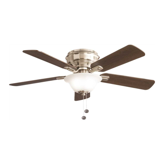
HAWKINS II 44 IN. CEILING FAN
Questions, problems, missing parts? Before returning to the store,
call Hampton Bay Customer Service
8 a.m. - 7 p.m., EST, Monday-Friday, 9 a.m. - 6 p.m., EST Saturday
Supply Works/Institutional - PH# 866-412-6726 x240212
Wilm ar/Multifamily - PH# 800-345-3000 x240755
Barnett/Specialty Trades - PH# 800-288-2000 x240410
THANK YOU
THANK YOU
Item #309766464
#309766463
#309766460
Model # YG204CI-BN
#YG204CI-ORB
#YG204CI-WH
Advertisement
Table of Contents

Related Manuals for HAMPTON BAY YG204CI-BN


Summary of Contents for HAMPTON BAY YG204CI-BN
- Page 1 HAWKINS II 44 IN. CEILING FAN Questions, problems, missing parts? Before returning to the store, call Hampton Bay Customer Service 8 a.m. - 7 p.m., EST, Monday-Friday, 9 a.m. - 6 p.m., EST Saturday Supply Works/Institutional - PH# 866-412-6726 x240212...
-
Page 2: Table Of Contents
Table of Contents Table of Contents ............Operation ..............Pull Chain Operating Instructions .......... Safety Information ............Reverse Switch Operating Instructions ........Warranty ................. Care and Cleaning ............Pre-installation .............. Troubleshooting ............Specifications ................Tools Required ................Service Parts ............... Hardware Included .............. -
Page 3: Safety Information
The fan must be mounted with a minimum of 7 ft (2.1m) responsible for this declaration: clearance from the trailing edge of the blades to the floor. Model Number: YG204CI-BN, YG204CI-ORB, YG204CI-WH Company Name: TAL INTERNATIONAL CORPORATION Avoid placing objects in the path of the blades. -
Page 4: Warranty
Warranty We warrant the fan motor to be free from defects in workmanship and material present at time of shipment from the factory for a period of lifetime after the date of purchase by the original purchaser. We also warrant that all other fan parts, excluding any glass or acrylic blades, to be free from defects in workmanship and material at the time of shipment from the factory for a period of one year after the date of purchase by the original purchaser. -
Page 5: Hardware Included
Pre-Installation (continued) HARDWARE INCLUDED HARDWARE INCLUDED NOTE: Hardware shown to actual size unless noted otherwise in the table below. Part Part Description Description Quantity Quantity Plastic wire nut Blade arm screw and lock washer (preassembled) Nut (preassembled) Washer (preassembled) Light kit mounting screw (preassembled) Metal nut (preassembled) Glass cap (preassembled) Decorative nut (preassembled) -
Page 6: Package Contents
Pre-Installation (continued) PACKAGE CONTENTS PACKAGE CONTENTS Part Part Description Description Quantity Quantity Part Part Description Description Quantity Quantity Mounting bracket Motor housing Fan motor assembly Light kit Blade Glass shade Blade arm... -
Page 7: Installation
Installation MOUNTING OPTIONS MOUNTING OPTIONS WARNING: To reduce the risk of fire, electric shock, or personal injury, mount the fan to an outlet box marked acceptable for fan support using the screws provided with the outlet box. An outlet box commonly used for the support of lighting fixtures may not be acceptable for fan support and may need to be replaced. -
Page 8: Assembly
Assembly — Hanging the Fan Hanging the fan to the Installing the mounting bracket mounting bracket to the electrical box □ Lift the fan into position by hanging the fan motor WARNING: To reduce the risk of fire, electric shock or assembly (B) onto the hook from the ceiling mounting other personal injury, mount the fan only to an outlet box or bracket (A) allowing it to hang freely. - Page 9 Assembly — Hanging the Fan (continued) Making the electrical connections Ground conductor WARNING: To avoid possible electrical shock, be sure Black White electricity is turned off at the main fuse box before wiring. WARNING: Check to see that all connections are tight, including ground, and that no bare wire is visible at the wire nuts (except for the ground wire).
- Page 10 Assembly — Hanging the Fan (continued) Finishing the fan Attaching the motor housing installation to the mounting bracket □ □ Move the fan motor assembly (B) into position over Raise the motor housing (E) up against the mounting the four mounting bracket studs and secure with the bracket (A).
-
Page 11: Attaching The Fan Blades
Assembly — Attaching the Fan Blades Attaching the blades to the blade arms WARNING: Failure to properly seat the blades (C) on the blade arms (D) and engage in the spring locking mechanism (OO) could result in the fan blades (C) loosening and possibly falling. -
Page 12: Installing The Light Kit
Assembly — Installing the Light Kit Attaching the light kit to the Installing the light bulbs switch housing CAUTION: Before starting installation, disconnect the CAUTION: Before starting installation, disconnect the power by turning off the circuit breaker or removing the fuse power by turning off the circuit breaker or removing the fuse at the fuse box. - Page 13 Assembly — Installing the Light Kit (continued) Installing the glass shade CAUTION: Before starting the installation, disconnect the power by turning off the circuit breaker or removing the fuse at the fuse box. Turning power off using the fan switch is not sufficient to prevent electric shock.
-
Page 14: Operation
Operation PULL CHAIN OPERATING INSTRUCTIONS PULL CHAIN OPERATING INSTRUCTIONS Install two pull chains and fobs (II) onto the pull chains located in the switch housing and light kit (F). Turn on the power and check the operation of the fan. The pull chain controls the fan speed as follows: 1 pull - High, 2 pulls - Medium, 3 pulls - Low and 4 pulls - Off. -
Page 15: Care And Cleaning
Care and Cleaning Do Do Do not Do not □ Use water when cleaning. Water could damage the motor, □ Check the support connections, brackets, and blade or the wood, or possibly cause an electrical shock. attachments twice a year. Make sure they are secure. Because of the fan’s natural movement, some □... -
Page 16: Troubleshooting
Troubleshooting WARNING: Make sure the power is off at the electrical panel box before you attempt any repairs. Refer to step 3 “Making the electrical connections” on page 9. Problem Problem Solution Solution □ Check the main and branch circuit fuses or breakers. The fan will not start. -
Page 17: Service Parts
Pull chain and fob 9 watt LED bulb Questions, problems, missing parts? Before returning to the store, call Hampton Bay Customer Service 8 a.m. - 7 p.m., EST, Monday-Friday, 9 a.m. - 6 p.m., EST Saturday Supply Works/Institutional - PH# 866-412-6726 x240212... - Page 18 Questions, problems, missing parts? Before returning to the store, call Hampton Bay Customer Service 8 a.m. - 7 p.m., EST, Monday-Friday, 9 a.m. - 6 p.m., EST Saturday Supply Works/Institutional - PH# 866-412-6726 x240212 Wilm ar/Multifamily - PH# 800-345-3000 x240755 Barnett/Specialty Trades - PH# 800-288-2000 x240410 Retain this manual for future use.