
Related Manuals for Heat Controller REG-81G


Summary of Contents for Heat Controller REG-81G
- Page 1 SERVICE MANUAL Room Air Conditioner with R-410A REG-81G REG-123G Heat Controller, Inc. • 1900 Wellworth Ave. • Jackson, MI 49203 • (517)787-2100 • www.heatcontroller.com...
-
Page 2: Table Of Contents
Service Manual Room Air Conditioner with R-410A Heat Controller, Inc. Table of Contents 1. PRECAUTION ........................2 1.1 Safety precautions ......................2 1.2 Warning ..........................2 1.3 Caution ...........................2 2. FEATURES AND PANEL .......................3 2.1 Features .........................3 2.2 Control panel illustration ....................4 3. UNIT DIMENSION ........................6 3.1 Unit dimensions: ......................6... -
Page 3: Precaution
Service Manual Room Air Conditioner with R-410A Heat Controller, Inc. 1. PRECAUTIONS 1.1 Safety precautions To prevent injury to the user and property damage, the following instructions must be followed. Incorrect operation may cause harm or damage. Before servicing unit, be sure to read this service manual. -
Page 4: Features And Panel
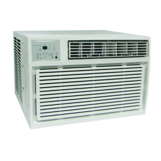
Service Manual Room Air Conditioner with R-410A Heat Controller, Inc. 2. FEATURES AND PANEL 2.1 Features Slide-in and Top-out chassis for simple installation and service (on some models). Washable one-touch filter and easy access panel. Super compact design. -
Page 5: Control Panel Illustration
Service Manual Room Air Conditioner with R-410A Heat Controller, Inc. 2.2 Control panel illustration Control panel (electric heating model) For J1 Series: Display Panel On/Off (On and Off): Press this button once to start the unit, press again to stop. - Page 6 Service Manual Room Air Conditioner with R-410A Heat Controller, Inc. MODE: Press this button to select operation mode. Each time you press the button, the operation mode is selected in a sequence that goes from Auto, Cool, Dry and Fan for cooling only models, and Auto, Cool, Dry, Heat and Fan for electric heating models.
-
Page 7: Unit Dimension
Service Manual Room Air Conditioner with R-410A Heat Controller, Inc. 3. UNIT DIMENSIONS 3.1 Unit dimensions: Series A (mm/inch) B (mm/inch) C (mm/inch) REG-81G/123G 574 / 22.6” 410 / 16.2” 584/ 23.0”... -
Page 8: Operation Limits
Service Manual Room Air Conditioner with R-410A Heat Controller, Inc. 4. OPERATION LIMITS 4.1 Cooling operation Outdoor unit air temp DB Indoor air temp DB Note: The chart is the result from the continuous operation under constant air temperature conditions. However, the initial pull-down stage is not included. -
Page 9: Protection Function
Service Manual Room Air Conditioner with R-410A Heat Controller, Inc. 5. PROTECTION FUNCTIONS 5.1 Symbol & Meaning TA: Indoor ambient temperature; TE: Indoor evaporator temperature; TS: Setting temperature through the remote controller. 5.2 Protection Functions Compressor Time Delay/Restart The compressor will wait for 3 minutes before restarting, to prevent the pressure imbalance in refrigerant system from causing a locked rotor compressor failure. -
Page 10: Component Operation & Testing
Service Manual Room Air Conditioner with R-410A Heat Controller, Inc. Fault Code Defect code Defect explanation Evaporator de-frosting defect. Indoor ambient temperature sensor failure ( heating, cooling, dry and auto mode) DAHT sensor failure in heating mode. Sensor disconnection malfunction in fan only mode Sensor short circuit malfunction in fan only mode 6. - Page 11 Service Manual Room Air Conditioner with R-410A Heat Controller, Inc. CHECKING COMPRESSOR EFFICIENCY The reason for compressor inefficiency is normally due to broken or damaged suction and/or discharge valves, reducing the ability of the compressor to pump refrigerant gas. This condition can be checked as follows: 1.
-
Page 12: Fan Motor
Service Manual Room Air Conditioner with R-410A Heat Controller, Inc. CHECKING THE INTERNAL OVERLOAD (see Figure 4.) 1. With no power to unit, remove the leads from the compressor terminals. 2. Using an ohmmeter, test continuity between terminals C-S and C-R. If not continuous, the compressor overload is open and the compressor must be replaced. -
Page 13: Thermostat Adjustment
Service Manual Room Air Conditioner with R-410A Heat Controller, Inc. CAPACITOR - TEST 1. Remove capacitor from unit. 2. Check for visual damage such as bulges, cracks, or leaks. 3. For dual rated, apply an ohmmeter lead to common (C) terminal and the other probe to the compressor (HERM) terminal. -
Page 14: Valve, Drain Pan (See Figure 7)
Service Manual Room Air Conditioner with R-410A Heat Controller, Inc. 6.6 VALVE, DRAIN PAN (see Figure 7) During the cooling mode of operation, condensate which collects in the drain pan is picked up by the condenser fan blade and sprayed onto the condenser coil. This assists in cooling the refrigerant plus evaporating the water. - Page 15 Service Manual Room Air Conditioner with R-410A Heat Controller, Inc. HERMETIC COMPONENT REPLACEMENT The following procedure applies when replacing components in the sealed refrigeration circuit or repairing refrigerant leaks. (Compressor, condenser, evaporator, capillary tube, refrigerant leaks, etc.) 1. Recover the refrigerant from the system at the line located on the high side of the system by installing a line tap on the line.
- Page 16 Service Manual Room Air Conditioner with R-410A Heat Controller, Inc. NOTE: If the entire charge will not enter the high side, allow the remainder to enter the low side in small increments while operating the unit. 12. Restart unit several times after allowing pressures to stabilize. Pinch off lines, cut and solder the ends.
-
Page 17: Wiring Diagram
Service Manual Room Air Conditioner with R-410A Heat Controller, Inc. 7. WIRING DIAGRAM The wiring diagram shown below is representative of models deployed with full features. Your model may not offer all these features, accordingly it may be slightly different from the wiring diagram in these optional features area. -
Page 18: Troubleshooting
Service Manual Room Air Conditioner with R-410A Heat Controller, Inc. 8. TROUBLESHOOTING In general, possible trouble is classified in three kinds. One is called Starting Failure which is caused from an electrical defect, another is ineffective Air Conditioning caused by a defect in the refrigeration circuit and improper application, and the other is called the Structure Damage. - Page 19 Service Manual Room Air Conditioner with R-410A Heat Controller, Inc. The "filter check" lamp is on. Press "filter check" button several times and check whether the problem stops. Replace the main control board. Button of remote controller doesn’t work. Check the power supply.
- Page 20 Service Manual Room Air Conditioner with R-410A Heat Controller, Inc. Operation panel don't work. Check the power supply. Press the "LED" button of remote controller several times and check whether the problem is settled down. Check the wiring of display board.
- Page 21 Service Manual Room Air Conditioner with R-410A Heat Controller, Inc. Display keeps showing "Ed". Check whether the evaporator is frosted. Check whether the indoor air inlet is blocked. Check whether the indoor ambient temperature is too low. Check whether the indoor filter is too dirty/clogged.
- Page 22 Service Manual Room Air Conditioner with R-410A Heat Controller, Inc. Compressor doesn’t work. Check whether the indoor temperature is lower than 59F (15°C). Check the power supply. Check whether the voltage is too high or too low. Check the wiring.
- Page 23 Service Manual Room Air Conditioner with R-410A Heat Controller, Inc. The fan motor doesn’t work. Check the power supply. Check whether the indoor (outdoor) fan is locked. Check the wiring. Check whether the relays on PCB for motor work normally.
- Page 24 Service Manual Room Air Conditioner with R-410A Heat Controller, Inc. The air conditioner doesn’t work. Check the power supply. Check the wiring. Check whether the transformer has failed. Measure the output voltage of transformer and check whether it is the range from +5V to 12V. If not, replace the transformer.
- Page 25 Service Manual Room Air Conditioner with R-410A Heat Controller, Inc. The compressor cycles on/off frequently. Check whether the airflow is blocked. Check if the fan motor isn’t working. Check whether capacitor of compressor is working normally. Check whether the relay of compressor on PCB works normally.
- Page 26 Service Manual Room Air Conditioner with R-410A Heat Controller, Inc. Water drips from the unit. Check whether the ambient humidity is too high. Check whether the indoor outlet airflow foam is wet if water is dripping from the louvers. Check whether the unit is correctly installed.
- Page 27 Service Manual Room Air Conditioner with R-410A Heat Controller, Inc. Not heating or not heating enough. (Cooling and Electric Heater) Check the setting mode. Check whether the airflow speed is too low. Check the heat load of the room. Check the specification of PTC-heater.
-
Page 28: General Troubleshooting
Service Manual Room Air Conditioner with R-410A Heat Controller, Inc. 8.2 General Troubleshooting PROBLEM P OSSIBLE CAUSE REMARK Check voltage at electrical outlet. Correct if No power none. Check voltage at the power cord terminal. Power supply cord Replace the power cord if none. - Page 29 Service Manual Room Air Conditioner with R-410A Heat Controller, Inc. PROBLEM OSSIBLE CAUSE REMARK Air filter Clean or replace if restricted. Vent door Close if open. Determine if the unit is properly sized for Unit undersized the area to be cooled or heated.
- Page 30 Service Manual Room Air Conditioner with R-410A Heat Controller, Inc. PROBLEM OSSIBLE CAUSE REMARK Check the voltage. Call an electrician if not No power within correct limits of +/- 10% of nominal voltage rating required. Wiring Check terminals. Repair and correct if loose.
-
Page 31: Troubleshooting Cooling
Service Manual Room Air Conditioner with R-410A Heat Controller, Inc. 8.3 Troubleshooting Cooling PROBLEM POSSIBLE CAUSE TO CORRECT Compressor Low voltage. Check for voltage at compressor. 115 volt does not run. and 230 volt units will operate at 10% voltage variance Thermostat not set cold enough Set thermostat to coldest position. - Page 32 Service Manual Room Air Conditioner with R-410A Heat Controller, Inc. PROBLEM POSSIBLE CAUSE TO CORRECT Unit does Fuse blown or circuit tripped. Replace fuse, reset breaker. If repeats, not run. check fuse or breaker size. Check for shorts in unit wiring and components.
-
Page 33: Troubleshooting Heating (Cooling/Electric Heater Models)
Service Manual Room Air Conditioner with R-410A Heat Controller, Inc. PROBLEM POSSIBLE CAUSE TO CORRECT Compressor Overload inoperative. Opens too Check operation of unit. Replace overload if attempts to soon. system operation is satisfactory. start, or runs Compressor attempts to start... - Page 34 Service Manual Room Air Conditioner with R-410A Heat Controller, Inc. PROBLEM POSSIBLE CAUSE TO CORRECT Fan motor Defective motor. Check and replace. does not Open or shorted capacitor. Replace capacitor and check. operate in Condenser fan frozen to Chassis. Check if drain pan valve is open. If not, "Constant"...
- Page 35 Service Manual Room Air Conditioner with R-410A Heat Controller, Inc. 10. TEMPERATURE SENSOR Temp.°F (°C) Resistance KΩ Temp.°F (°C) Resistance KΩ Temp.°F (°C) Resistance KΩ 14 (-10) 62.2756 62.6 (17) 14.6181 111.2 (44) 4.3874 16 (-9) 58.7079 64.4 (18) 13.918 113 (45) 4.2126...
- Page 36 03/2010 04/2009...