Advertisement
Quick Links
Advertisement

Related Manuals for Robertshaw RS9210


Summary of Contents for Robertshaw RS9210
- Page 1 RS9210 Insta llation Ma nual...
-
Page 3: Table Of Contents
INSTALLATION MANUAL Thank you for purchasing a Robertshaw thermostat. This manual will describe how to ® install and test the Robertshaw RS9210 thermostat. Thermostat System Types Gas, Oil, or Electric Heat with Air Conditioning IMPORTANT SAFETY INFORMATION Heat Pumps (with or without auxiliary or emergency heat) -
Page 4: Installation Location
INSTALLATION LOCATION Install the thermostat 4 to 5 feet above the floor in an area with good air circulation and average temperature. For new installations, mount thermostat on an inside wall, 4-5 feet above the floor. Do not install the thermostat in the following locations: •... -
Page 5: Thermostat Quick Reference
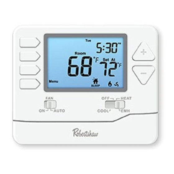
THERMOSTAT QUICK REFERENCE Getting to know your thermostat Displays the user Days of the week selected set-point and time. Hold: Is Room temperature. Set At displayed when thermostat Sun Mon Tue Wed Thu Fri Sat Tech Set program is Min Com On Next overridden. -
Page 6: Wallplate Installation
WALLPLATE INSTALLATION Caution: Mercury Notice: This product is mercury-free. However, Electrical Hazard if this product is replacing a control Disconnect power before installing which contains mercury, it needs to this product. Failure to do so can be disposed of properly. Contact your cause electric shock or equipment local waste management authority for damage. -
Page 7: Wiring
WIRING 1 Turn Off Power to Heating/Cooling System Circuit breaker Heating/cooling system power switch 2 Remove Old Thermostat Remove old thermostat but leave wallplate with wires attached. Do not remove wallplate Terminal designation... - Page 8 WIRING 3 Label Wires with Tags 4 Separate Wallplate from New Thermostat Label the wires using the supplied wire labels as you disconnect them. Remove wallplate from the new thermostat and mount onto wall. Wiring Labels Apply these wiring labels to each wire with the appropriate terminal designation as you remove it from the existing thermostat.
- Page 9 WIRING 5 Mount Wallplate for New Thermostat Mount the new wallplate using the included screws and anchors. Drill 3/16-in. holes for drywall Drill 3/16-in. holes for plaster...
- Page 10 WIRING 6 Connect Wires Simply match wire labels. If labels do not match letters on the thermostat, check “Alternate Wiring (Conventional Systems)” on page 9 and connect to terminal as shown (see notes, below). INSERT WIRES AND SCREW TIGHTEN SCREWS...
- Page 11 WIRING Alternate Wiring (Conventional Systems) If labels do not match letters on the thermostat, check the chart below and connect to terminal as shown here (See notes, below). If there is a C or X wire available then you can connect with C terminal. If there is no C or X wire then no need to connect with C terminal.
- Page 12 WIRING Terminal Designations Conventional System Heat Pump System 1 HEAT 1 COOL / 2 HEAT 1 COOL 1 HEAT 1 COOL / 2 HEAT 1 COOL Transformer Power Transformer Power Transformer Common Transformer Common Reversing Valve Energized in HEAT Energized in HEAT Reversing Valve Energized in COOL Energized in COOL...
- Page 13 WIRING Power supply. Use either O or B terminals for reversing valve. Optional 24 VAC common connection when thermostat is used in battery power mode. Jumper (not supplied). 2H/1C Heat Pump System Note: In many systems with no emergency heat relay a jumper can be used between E and W2.
- Page 14 WIRING Typical 2H/1C Heat Pump System with separate emergency heat (HOT) COMPRESSOR RELAY COOL REVERSING EMERGENCY VALVE RELAY HEAT REVERSING VALVE FAN RELAY AUXILIARY (Heat pump set to OFF in tech settings) Conventional System 1H/1C, 2H/1C Note: This thermostat is only compatible with (HOT) ONE transformer...
-
Page 15: Installer Setup Menu
INSTALLER SETUP MENU Installer Setup Menu This thermostat has an installer setup menu for easy configuration. Follow the procedure below to set up the thermostat to match the specific heating/cooling system. Press MENU. Press and hold TECH SET for 3 seconds. Configure the installer options as desired using the table on page 14. - Page 16 INSTALLER SETUP MENU Settings Display Adjustment Options Default The filter change reminder This setting will flash FILT in can be adjusted from OFF Filter Next step the display after the elapsed to 2000 hours in 50 hour Change run time to remind the user to increments.
- Page 17 INSTALLER SETUP MENU Settings Display Adjustment Options Default Next step The compressor short cycle delay setting will not allow the Compressor The compressor short compressor to be turned on Short Cycle cycle delay setting can be for 5 minutes after it was last removed by selecting OFF.
- Page 18 INSTALLER SETUP MENU Settings Display Adjustment Options Default Next step Select F for Fahrenheit F for Fahrenheit F or C temperature display or select C for Celsius display. C for Celsius Prev step Next step 12 or 24 Select a 12 or 24 hour Hour clock setting.
- Page 19 INSTALLER SETUP MENU Settings Display Adjustment Options Default This thermostat can be configured to have 7 Day, 5+1+1 programming or be non-programmable. Next step If 7 Day is selected, in Set Time all seven days will need to be programmed individually. Program to select 7d for 7 Day, If 5+1+1 programming is selected,...
-
Page 20: Mounting & Battery Installation
MOUNTING & BATTERY INSTALLATION Mounting Thermostat Align the 4 tabs on the faceplate with the corresponding slots on the back of the thermostat, then push gently until the thermostat snaps into place. Room Set At Menu SLEEP HEAT AUTO COOL Battery Installation Battery installation is optional if used with AC power (the C terminal is connected). -
Page 21: Programming
PROGRAMMING Set Time of Day and Day of Week Press MENU. Press SET TIME. Day of the week will be flashing. Use to select the current day of the week. Press NEXT STEP. The current hour will be flashing. Use to select the current hour. - Page 22 PROGRAMMING Default Program This thermostat is pre-programmed for energy saving operation. The default program is below: Default Program Day of the Set-Point Set-Point Events Time Temperature (Heat) Temperature (Cool) Week Weekday 6 a.m. 70° F (21° C) 75° F (24° C) Wake 8 a.m.
- Page 23 PROGRAMMING You can use the table below to plan your customized program schedule. Custom Program Day of the Set-Point Set-Point Events Time Week Temperature (Heat) Temperature (Cool) Weekday Wake Leave Return Sleep Saturday Wake Leave Return Sleep Sunday Wake Leave Return Sleep...
- Page 24 PROGRAMMING Custom Programming This thermostat can be configured to have 7 Day or 5+1+1 programming. If 7 Day is selected, all seven days will need to be programmed individually. If 5+1+1 programming is selected, Monday–Friday will be programmed together and Saturday and Sunday will need to be programmed individually. There are four time periods for each day (WAKE, LEAVE, RETURN, SLEEP).
-
Page 25: Specifications
SPECIFICATIONS Specifications Temperature Display Range ......41°F to 95°F (5°C to 35°C) Temperature Control Range ......44°F to 90°F (7°C to 32°C) Load Rating ..........1 amp per terminal, 1.5 amp maximum all terminals combined Display Accuracy ........± 1°F Differential ........... Heating is adjustable from 0.2°F to 2.0°F Cooling is adjustable from 0.2°F to 2.0°F Power Source.......... - Page 28 Customer Service +1.800.304.6563 Technical Service +1.800.445.8299 Use Phone Year HVACCustomerService@robertshaw.com to Scan for Limited www.robertshaw.com • 352-00301-001 352-00304-0016 Rev. B Warranty Info Warranty © 2021 Robertshaw Controls Company. Robertshaw is a trademark of Robertshaw Controls Company. ®...