Table of Contents
Advertisement
Available languages
Available languages
Quick Links
INSTALLATION MANUAL
RS4000C Series
QUICK START
RS
RS
RS
RS5220C
STEP 1 Pull backplate straight out
to remove
STEP 2 Install backplate on the wall
and wire
STEP 3 Push front onto backplate
STEP 4 Remove tape on cover
STEP 5 Rotate cover up and remove
battery tray
STEP 6 Place batteries in tray and
place in thermostat
1
4220C
4320C
RS
5220C
6 220C
RS
6
352-00061-001 Rev D
RS6000C Series
20C
3
Advertisement
Table of Contents

Related Manuals for Robertshaw RS4000C Series


Summary of Contents for Robertshaw RS4000C Series
- Page 1 4220C 4320C 5220C 6 220C 352-00061-001 Rev D INSTALLATION MANUAL RS4000C Series RS5220C RS6000C Series QUICK START STEP 1 Pull backplate straight out to remove STEP 2 Install backplate on the wall and wire STEP 3 Push front onto backplate STEP 4 Remove tape on cover...
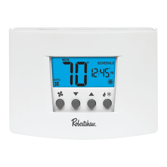
- Page 2 Thank you for purchasing a Robertshaw thermostat. This manual will ® describe how to install and test the Robertshaw two stage RS4220C, RS5220C, RS6220C and three stage* RS4320C, RS6320C thermostats. For complete operation instructions, refer to the Robertshaw User Manual.
- Page 3 IMPORTANT SAFETY INFORMATION WARNING: • Always turn off power at main fuse or circuit breaker panel before installing, removing, cleaning, or servicing thermostat. • Read all the information in this manual before installing this thermostat. • This is a 24V AC low-voltage thermostat. Do not install on voltages higher than 30V AC.
-
Page 4: Maintaining The Batteries
Installing the Robertshaw Thermostat Base NOTE: For new installations, mount the thermostat on an inside wall, five feet above the floor. Do not install behind a door, in a corner, near air vents, in direct sunlight, or near any heat or steam generating fixtures. -
Page 5: Connecting The Wires
System Switch Selection The body of the thermostat has two switches on the backside. They are accessible by removing the backplate from the body. The installer should set these to match the system. If the thermostat is controlling a heat pump system, set the first switch to Heat Pump. - Page 6 Two Stage Models RS4220C, RS5220C and RS6220C EQUIPMENT TO TERMINAL DESCRIPTION CONNECT 24V AC Connect to fault signal for input from Compressor Fault a compressor. Output Second stage Energizes on a call for second stage cooling cooling (aux.). connection. Second stage Energizes on a call for second stage heat connection heating (aux.).
-
Page 7: Wiring Diagrams
Wiring Diagrams When used as Heat Pump with Cool Active Reversing Valve With Battery Transformer 24 Vac 120 Vac Remove jumper if RH/R separate cooling Relay transformer is Reversing present. Valve Compressor Compressor Fault Output Contactor (24VAC) Second Stage Cool Second Stage Heat Emer Heat... - Page 8 Wiring Diagrams When used as Non-Heat Pump With Battery Backup Transformer 24 Vac 120 Vac Remove jumper if separate cooling RH/R Relay transformer is present. Compressor Contactor First Stage Heat Second Stage Cool Second Stage Heat Make certain the HP switch is in the Non-HP position. When used as Heat Pump with Cool Active Reversing Valve With Battery Backup Transformer...
-
Page 9: Applying Power
Applying Power Before applying power, fill in the chart in the Pop-Up Wizard section of this manual. When 24V AC power or battery power is first applied to the thermostat, the display will show the model number followed by the Pop-Up Wizard. The thermostat will start normal operation following the Pop-Up Wizard. - Page 10 Pop-Up Wizard The Wizard routine will display factory default settings. Each setting will display for ten seconds. Use the buttons to change the setting. Settings that are not changed will operate with the values that are displayed. To fast forward through the Wizard, press Edit Schedule. The Wizard can be exited by pressing Start/Stop Schedule.
- Page 11 Default Settings for RS5220C, RS6220C and RS6320C The RS5220C and RS6320C series are programmable thermostats and are preprogrammed with a recommended schedule. The schedule is designed to lower energy costs year-round. Temperature Settings Winter (Heating) Summer (Cooling) Morning (6:00 am) 70 °F (21 °C) 78 °F (25 °C) Day (8:00 am) 62 °F (17 °C)
-
Page 12: Setting The Mode
Press to step through the following: Installation Tests for Multi-Stage Models Conventional (Non-HP) Heat Pump (HP) Demand Terminal Display Terminal Display First Stage Heat W1 + G* Y1 + G + B Second Stage W1 + W2 + G* Y1 + W2 +G + B Heat Third Stage / E + G Emergency Heat First Stage Cool... - Page 13 Setting Mode to Emergency Heat The multi-stage thermostats have have an emergency heat capability for heat pump systems. An E will be displayed with the heat symbol . Use emergency heat to turn off the heat pump and turn on a secondary heating source. This mode is used to bypass the heat pump when it needs servicing or when it cannot keep up with the heat demand.
-
Page 14: Thermostat Specifications
Thermostat Specifications Operating Voltage 18-30V AC Maximum Load Current 1 Amp Max per Output Terminal 4 Amp Total Load Output Type Latching Relays Batteries 2 AA Alkaline in Series Battery Life 2 Years Typical Ambient Operating Temperature 14 °F (-10 °C) to 122 °F (50 °C) Storage Temperature -4 °F (-20 °C) to 140 °F (60 °C) Operational Mode Chart:... -
Page 15: Troubleshooting
Troubleshooting Problem Action Thermostat does not turn on Check wiring system. (see Wiring Diagrams section). Increase temperature differential System turns on too often. (see Pop-Up Wizard section). Move fan option switch to either System fan does not operate gas or electric, to match system properly. - Page 16 Invensys Controls warrants to the original contractor installer, or to the original consumer user, that each new Robertshaw thermostat will be free from defects in materials and workmanship under normal use and service for a period of five (5) years from the date of purchase (the “Warranty Period”).
- Page 17 191 E. North Avenue www.Uni-Line.com Carol Stream Illinois 60188 USA Invensys™ and Robertshaw are trademarks of Invensys ® www.InvensysControls.com Customer Service Telephone 1.800.304.6563 plc., its subsidiaries and/or affiliated companies. All ©2011 Invensys Controls Customer Service Facsimile 1.800.426.0804 other brands mentioned may be the trademarks of their HVACCustomerService@Invensys.com...
-
Page 18: Manuel D'installation
4220C 4320C 5220C 6 220C 352-00061-001 Rev D MANUEL D’INSTALLATION Série RS4000C RS5220C Série RS6000C MISE EN SERVICE RAPIDE ÉTAPE 1 Tirez directement la plaque arrière pour la retirer ÉTAPE 2 Installez la plaque arrière sur le mur et câblez ÉTAPE 3 Enfoncez la face sur la plaque arrière ÉTAPE 4 Retirez le film du couvercle... - Page 19 RS4220C pour deux étages d’équipement, du RS5220C, RS6220C et des RS4320C et RS6320C pour trois étages* d’équipement. Consultez le manuel de l’utilisateur Robertshaw pour les instructions complètes. Utilisez le numéro du modèle pour identifier votre thermostat. R S X 1 1 0...
- Page 20 MISE EN GARDE ET CONSIGNES DE SÉCURITÉ IMPORTANTES : • Coupez toujours l’alimentation électrique au niveau du fusible ou du disjoncteur principal avant d’installer, de retirer, de nettoyer ou de dépanner le thermostat. • Lisez toute l’information de ce manuel avant d’installer ce thermostat. •...
-
Page 21: Entretien Des Piles
Robertshaw REMARQUE : Pour les nouvelles installations, fixez le thermostat sur un mur intérieur, à une hauteur de 1,50 m. Ne l’installez pas derrière une porte, dans un coin, près des bouches d’air, à l’exposition directe du soleil ou près d’une source de chaleur ou de vapeur. - Page 22 Sélection des interrupteurs du système Le corps du thermostat est muni de deux interrupteurs au verso. Il faut retirer la plaque arrière du corps pour les voir. L’installateur doit les régler de manière à correspondre au système. Si le thermostat contrôle une pompe à chaleur, mettez le premier interrupteur en position de pompe à...
- Page 23 Modèles RS4220C, RS5220C et RS6220C pour deux étages d’équipement ÉQUIPEMENT À BORNE DESCRIPTION RACCORDER Sortie d’erreur Raccordez au signal d’erreur pour recevoir les du compresseur données du compresseur. 24 V c.a. Raccord du 2 ème Activé par un appel de second étage étage d’équipement d’équipement de climatisation (aux).
-
Page 24: Schéma De Câblage
Schéma de câblage Utilisation en mode de pompe à chaleur avec valve à inversion activée en climatisation avec piles Transformateur Chargé Retirez le cavalier 24 Volts c.a. 120 c.a. s’ilexiste un Relais de RH/R transformateur ventilateur de climatisation Valve à séparé... - Page 25 Schéma de câblage Utilisé en mode de non-pompe à chaleur (Non-Heat Pump) avec piles de secours Transformateur Chargé 120 c.a. 24 Volts c.a. Retirez le cavalier Relais de RH/R s’ilexiste un ventilateur transformateur de climatisation séparé Contacteur du compresseur étage d’équipement de chauffage étage...
-
Page 26: Mise En Circuit
Mise en circuit Avant de fournir l’alimentation électrique, complétez le tableau dans la section du guide intelligent de ce manuel. Lorsque le thermostat est alimenté pour la première fois en 24 V c. a. ou avec des piles, l’écran affiche le numéro du modèle et ensuite le guide intelligent. - Page 27 Guide intelligent Le guide intelligent affichera les réglages d’usine. Chaque réglage sera affiché pendant dix secondes. Utilisez les touches pour changer le réglage. Les réglages non modifiés fonctionneront avec les valeurs affichées. Pour défiler rapidement à travers la séquence du guide intelligent, appuyez sur «...
- Page 28 Réglages pour RS5220C, RS6220C et RS6320C Les modèles des séries RS5000 et RS6000 sont des thermostats programmables et ils sont programmés avec un calendrier recommandé. Ce programme est conçu pour abaisser les coûts énergétiques pendant toute l’année. Réglages de la température Hiver (chauffage) Été...
- Page 29 Appuyez sur pour faire dérouler les éléments suivants : Tests de l’installation pour les modèles avec plusieurs étages d’équipement Conventionnel (non ther- Pompe à chaleur (« HP ») mopompe « Non-HP ») Demande Borne Affiché Borne Affiché étage d’équipement W1 + G* Y1 + G + B de chauffage étage...
- Page 30 Réglage en mode de chauffage d’urgence Les thermostats pour matériel multi-étagé ont une capacité de chauffage d’urgence pour les systèmes avec thermopompes. Un E sera affiché avec le symbole du chauffage . Utilisez le chauffage d’urgence pour éteindre la pompe à chaleur et mettre en route une source de chaleur auxiliaire.
-
Page 31: Caractéristiques Du Thermostat
Caractéristiques du thermostat Tension 18-30V c. a. Courant Maximum 1 Amp max par borne de sortie; 4 Amp de charge totale Type de sortie Relais de verrouillage Piles 2 piles AA Alcalines en série Durée de vie des piles 2 ans, en général Température ambiante de fonctionnement -10 °C (14 °F) à... - Page 32 Vérification-dépannage Problème Action Le thermostat ne met pas le sys- Vérifiez le câblage (Voir la section tème en route. sur les schémas de câblage). Augmenter le différentiel de la Le système se met en route trop température (Voir la section sur le souvent.
- Page 33 Garantie limitée de dix-huit mois Invensys Controls garantit à l’installateur sous-traitant d’origine, ou à l’utilisateur consommateur d’origine, que chaque thermostat Robertshaw neuf ne comportera aucun défaut de pièces et de main d’œuvre dans des conditions d’utilisation et d’entretien normales pendant une période de dix-huit (18) mois à...
- Page 34 Invensys Controls Service de la Garantie 3505 Laird Road Unit #14 Mississauga, Ontario L5L 5Y7 Canada Invensys™ et Robertshaw ® sont des marques commerciales 191 E. North Avenue www.Uni-Line.com appartenant à Invensys plc., à ses filiales et/ou sociétés Carol Stream Illinois 60188 USA www.InvensysControls.com...