
Related Manuals for Gree GPC10AL-K6NNA1A


Summary of Contents for Gree GPC10AL-K6NNA1A
- Page 1 Service Manual Change for Life Service Manual Models: GPC10AL-K6NNA1A GPH10AL-K6NNA1A GPC10AL-K6NNA2A GPC10AL-K6NNA3A (Refrigerant R32) GREE ELECTRIC APPLIANCES,INC.OF ZHUHAI...
-
Page 2: Table Of Contents
Service Manual Table of Contents Part Ⅰ : Technical Information ..............1 1. Summary .........................1 2. Specifications .....................3 3. Outline Dimension Diagram ..............7 4. Refrigerant System Diagram ..............9 5. Electrical Part ....................10 5.1 Wiring Diagram .......................10 5.2 PCB Printed Diagram .....................12 6. -
Page 3: Part Ⅰ : Technical Information
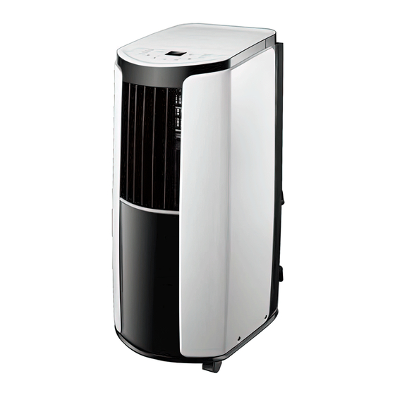
Service Manual Part Ⅰ : Technical Information 1. Summary Models: GPC10AL-K6NNA1A GPH10AL-K6NNA1A Model: GPC10AL-K6NNA2A Technical Information... - Page 4 Model: GPC10AL-K6NNA3A Remote Controller: YB1F2(XFAN) AUTO HEALTH X-FAN HUMIDITY FILTER TURBO HOUR ON/OFF ON/OFF MODE X-FAN TEMP TIMER TURBO SLEEP LIGHT Models list: GPC10AL-K6NNA1A CK010026000 GPC10AL-K6NNA1A CK010026001 GPC10AL-K6NNA2A CK010027700 GPC10AL-K6NNA2A CK010027701 YB1F2(XFAN) GPC10AL-K6NNA3A CK010027600 GPC10AL-K6NNA3A CK010027601 GPH10AL-K6NNA1A CK010026100 Technical Information...
-
Page 5: Specifications
Service Manual 2. Specifications Parameter Unit Value 1.GPC10AL-K6NNA1A Model 2.GPC10AL-K6NNA2A GPH10AL-K6NNA1A 3.GPC10AL-K6NNA3A 1.CK010026000/CK010026001 Product Code 2.CK010027700 CK010026100 3.CK010027600 Rated Voltage V ~ 220-240 220-240 Power Rated Frequency Supply Phases Cooling Capacity 2930 2930 Heating Capacity 2930 Cooling Power Input Heating Power Input... - Page 6 Service Manual ZHUHAI LANDA COMPRESSOR ZHUHAI LANDA COMPRESSOR Compressor Manufacturer/Trademark CO., LTD CO., LTD Compressor Model QXF-B098A030 QXF-B098A030 Compressor Oil POE(RB68EP) POE(RB68EP) Compressor Compressor Type Rotary Rotary L.R.A. 22.00 22.00 Compressor RLA 3.25 3.25 Compressor Power Input Overload Protector UP3-A1 UP3-A1 Fan Type Centrifugal...
- Page 7 Service Manual Parameter Unit Value Model GPC10AL-K6NNA2A GPC10AL-K6NNA3A Product Code CK010027701 CK010027601 Rated Voltage V ~ 220-240 220-240 Power Rated Frequency Supply Phases Cooling Capacity 2930 2930 Heating Capacity Cooling Power Input Heating Power Input Cooling Power Current Heating Power Current Rated Input 1150 1150...
- Page 8 Service Manual ZHUHAI LANDA COMPRESSOR ZHUHAI LANDA COMPRESSOR Compressor Manufacturer/Trademark CO., LTD CO., LTD Compressor Model QXF-B098A030 QXF-B098A030 Compressor Oil POE(RB68EP) POE(RB68EP) Compressor Compressor Type Rotary Rotary L.R.A. 22.00 22.00 Compressor RLA 3.25 3.25 Compressor Power Input Overload Protector UP3-A1 UP3-A1 Fan Type Centrifugal...
-
Page 9: Outline Dimension Diagram
Service Manual 3. Outline Dimension Diagram GPC10AL-K6NNA1A GPH10AL-K6NNA1A Unit:mm Technical Information... - Page 10 Service Manual GPC10AL-K6NNA2A Unit:mm GPC10AL-K6NNA3A Unit:mm Technical Information...
-
Page 11: Refrigerant System Diagram
Service Manual 4. Refrigerant System Diagram GPC10AL-K6NNA1A GPC10AL-K6NNA2A GPC10AL-K6NNA3A CENTRIFUGAL FAN CENTRIFUGAL FAN COOLED AIR HOT DISCHARGED AIR COMPRESSOR INDOOR COILS OUTDOOR COILS CAPILLARY REFRIGERANT FLOW DIRECTION GPH10AL-K6NNA1A 4-Way valve COOLED AIR CENTRIFUGAL FAN CENTRIFUGAL FAN HOT DISCHARGED AIR HOT AIR... -
Page 12: Electrical Part
Symbol Name White Green COMP Compressor Yellow Brown Grounding wire Blue YEGN Yellow/Green Black Violet Orange ●Electric Diagram Models:GPC10AL-K6NNA1A GPC10AL-K6NNA2A GPC10AL-K6NNA3A TUBE TEMP. OUTTUBE TEMP. RECEIVER ROOM TEMP. SENSOR SENSOR SENSOR BOARD COLD PLASMA POWER GENERATOR BN(BK) BU(WH) DISPLAY BOARD... - Page 13 Service Manual Model:GPH10AL-K6NNA1A ROOM TEMP. TUBE TEMP. OUTTUBE TEMP. WATER MOTOR COLD PLASMA SENSOR SENSOR SENSOR RECEIVER POWER GENERATOR BN(BK) YEGN BOARD BU(WH) YEGN(GN) HEALTH-NHEALTH-L ROOM TUBE OUTTUBE WATER DISP2 AC-L DISP2 MAIN BOARD K201 YEGN COMP. DISP1 COMP COMP R(M) DISP1 OFAN...
-
Page 14: Pcb Printed Diagram
Service Manual 5.2 PCB Printed Diagram (1)Silk screen on main board TOP VIEW NAME Piezoresistor Fuse Copper fin N2 of neutral wire Copper fin N1 of neutral wire Copper fin N3 of neutral wire Indoor fan 4-way valve terminal Neutral wire terminal Outdoor fan Copper fin water of motor Copper fin Health of live wire... - Page 15 Service Manual (2)Silk screen on display board TOP VIEW Interface of main board BOTTOM VIEW Technical Information...
-
Page 16: Function And Control
Service Manual 6. Function and Control 6.1 Introduction of control panel Dual-8 nixie tube + / - button Cool mode indicator Health indicator(Optional) Dry mode indicator Fan mode indicator Heat mode indicator Cool&Heat Unit only Fan speed indicator Mode button Sleep button Timer button Fan button... -
Page 17: Remote Controller Introduction
Service Manual 6.2 Remote Controller Introduction Buttons on Remote Controller ON/OFF button AUTO MODE button HEALTH X-FAN HUMIDITY +/- button FILTER TURBO FAN button HOUR ON/OFF button(Not applicable for this unit) button(Not applicable for this unit) ON/OFF MODE HEALTH SAVE button X-FAN button (Note: X-FAN is same with BLOW) TEMP button... - Page 18 Service Manual 1.ON/DFF button Press this button can turn on or turn off the air conditioner. After turning on the unit,operation indicator " " on the unit is ON (green indicator. Color may be different for different models) and the unit gives out a sound. 2.MODE button Press this button can select your required operation mode.
- Page 19 Service Manual 9.TEMP button Press this button can see indoor set temperature, indoor ambient temperature or outdoor ambient temperature on the units display. Temperature is set circularly by remote controller as below: no display ● When selecting " " by remote controller or no display, temperature indicator on the unit displays set temperature.
- Page 20 Service Manual NOTICE: ● During operation, point the remote control signal sender at the receiving window on the unit. ● The distance between signal sender and receiving window should be no more than 8m, and there should be no obstacles between them.
-
Page 21: Introduction Of Basic Mode Function
Service Manual 6.3 Introduction of Basic Mode Function 1. Temperature Parameter ◆ Indo or setting temperature (Tpreset) ◆ Indoor ambient temperature (Tamb.) 2. Basic Functions of System After the unit is energized, the interval of start-up time for compressor is no less than 3min under any conditions; when the compressor is started, the unit is off without the temperature change in 6min. - Page 22 Service Manual 3.7 Setting button function a) ON/OFF button: It controls systems switch. b) Mode button: Mode setting cycle with below sequence: Cooling only unit: cooling-> dry-> fan. c) Temp. ▼ button: Set temperature when the unit is on, the setting temperature decreases 1 C or F per press Temp.
-
Page 23: Part Ⅱ : Installation And Maintenance
Service Manual Part Ⅱ : Installation and Maintenance 7. Notes for Installation and Maintenance Safety Precautions: Important! 11. Replace the fuse with a new one of the same specification Please read the safety precautions carefully before if it is burnt down; dont replace it with a cooper wire or installation and maintenance. - Page 24 Service Manual Safety Precautions for Refrigerant 1. To realize the function of the air conditioner unit, a special refrigerant circulates in the system. The used refrigerant is the fluoride R32,which is specially cleaned. The refrigerant is flammable and inodorous. Furthermore, it can leads to explosion under certain conditions.
- Page 25 Service Manual Main Tools for Installation and Maintenance 1. Level meter, measuring tape 2.Screw driver 3.Scissors, saw 4.Electroprobe 5. Universal meter 6.Torque wrench, open-end wrench, inner hexagon spanner 7. Electronic leakage detector 8. Vacuum pump 9. Pressure meter 10. Pipe pliers, pipe cutter 11.
-
Page 26: Install
Service Manual Installation procedures Start installation Preparation before installation Read the requirements Prepare tools for electric connection Install wire hook Install drainage pipe Install window frame Install heat discharge pipe and joint pack up heat discharge pipe Check after installation and test operation Finish installation Note: this flow is only for reference;... - Page 27 Service Manual Optional Window panel Exhaust cover Extension panel Adjustment panel Insect guard net Rain guard (2) Window kit screw(5) Bracket foam seal A(2) foam seal B Maintenance...
-
Page 28: Removing Collected Water
Service Manual 8. Install 8.1 Install Wire Hook ● Assemble the wire hook at the back of the unit with screws.(As show in Fig.1) direction of wire hook is upward wire hook screw direction of wire hook is downward Fig.1 Fig.2 ●... - Page 29 Service Manual ● Drainage way as follows. 1. In Cool, Dry or Heat mode operating, the condensation water will be drained to the chassis.(As show in Fig.6) 2. When the chassis is full with water, the buzzer will give out 8 sounds and "H8" is displayed to remind user to discharge water: ●...
-
Page 30: Installation In A Double-Hung Sash Window
Service Manual 8.3 Installation in a double-hung sash window 1. Connect the rain guards to the insect guard net.(As show in Fig.10) Insert all three projections on each rain guard into the holes in the insect guard net. Side “A” will now be at the top, as indicated in the diagram. 2. -
Page 31: Installation In A Sliding Sash Window
Service Manual 5. Cut the foam seal B to the proper length and attach it to the window panel.(As show in Fig.19) 6. Close the window sash securely against the Window panel.(As show in Fig.20) Fig.19 Fig.20 7. Attach the bracket with a screw.(Recommended)(As show in Fig.21) Bracket Fig.21 Please lay a tabular material underneath the window panel in case you could not attach the rain guard or the window adapter properly... - Page 32 Service Manual Inner height of the window:20.5" (520mm)- 38.5" (980mm) Use the window panel and the adjustment panel. (1) Open the window sash and place the window panel on the window frame. (2) Slide the adjustment panel to fit the window frame height.(As show in Fig.27) (3) Secure the window panel to the window frame with 3 screws.(As show in Fig.28) Adjustment panel 20.5"...
-
Page 33: Installation And Disassembly Of Heat Discharge Pipe
Service Manual 8.5 Installation and Disassembly of heat Discharge Pipe A. Install heat discharge pipe (1) Rotate joint A and joint B clockwise into the two ends of heat discharge pipe.(As show in Fig.10) (2) Insert joint A of heat discharge pipe (the side with "TOP" is upwards) into the groove until you hear a sound.(As shown in Fig.11) (3) Lead the exhaust hose outdoors.(As shown in Fig.12) (4) Slide and open the exhaust cover on the window panel, and attach the window adapter. -
Page 34: Operation Test
Service Manual ●Correct installation is as shown in figure (When installing it on wall, height of hall should be about 40cm-130cm from floor).(As shown in Fig.15) ●Wrong installation is shown in following figure (If the pipe is bent too much, it would easily cause malfunction.(As shown in Fig.16) B. -
Page 35: Maintenance
Service Manual 9. Maintenance 9.1 Error Code Display Method of Indoor Unit Indicator lamp (During blinking, ON for 0.5S and NO. Malfunction OFF for 0.5 S) A/C Status Possible Causes Error Name Code Operation COOL HEAT Inidicato Indicator Indicator 1. The wiring terminal between indoor ambient temperature sensor and main board is loosened or poorly contacted. - Page 36 Service Manual Display Method of Indoor Unit Indicator lamp (During blinking, ON for 0.5S and Malfunction OFF for 0.5 S) A/C Status Possible Causes Error Name Code Operation COOL HEAT Inidicato Indicator Indicator During cooling or drying operation,condensate water will flow into Water chassis.
-
Page 37: Malfunction Detection Flowchart
Service Manual 9.2 Malfunction Detection Flowchart (1) Malfunction of temperature sensor F1, F2, F4 Troubleshooting for F1,F2,F4 malfunction the wiring terminal between the temperature sensor and the controller loosened or poorly contacted? Insert the temperature sensor tightly Is malfunction eliminated Is there short circuit due to trip - over of the parts? Make the parts upright... - Page 38 Service Manual (2) Malfunction of Overcurrent Protection E5 Troubleshooting for E5 malfunction Is the supply voltage unstable Normal fluctuation is within 10 % of the rated Malfunction is with big fluctuation? voltage on the nameplate eliminated Is the supply voltage too low Malfunction is Adjust the supply voltage to maintain it within Malfunction is...
- Page 39 Service Manual (3) Bucket full protection H8 Start up the unit H8 is displayed Discharge water by referring Whether water tray is full to instruction manual Check whether wires for water-level Whether malfunction switch are connected tightly is eliminated? Adjust connection Whether malfunction Replace water-level is eliminated?
- Page 40 Service Manual (4) Malfunction of Insufficient fluorine protection F0 (4) Troubleshooting for F0 malfunction Heat exchangers are Clean the heat exchangers and remove Malfunction is too dirty or the air inlet/outlet eliminated. blockage of air inlet/outlet. is blocked. Compressor doesn't work Malfunction is Make compressor run normally.
- Page 41 Service Manual (5) (5) Malfunction of Overload protection for compressor H3 Troubleshooting for H3 malfunction Heat exchangers are Clean the heat exchangers and remove Malfunction is too dirty or the air inlet/outlet eliminated. blockage of air inlet/outlet. is blocked. Fan motor is not working Check motor and re-install the moto Malfunction is Abnormal fan speed;...
- Page 42 Service Manual (6) Overload malfunction E8 Troubleshooting for E8 malfunction Operate the unit after ambient tempeature and Whether the environment Malfunction is humidity is decreased or move the unit to the eliminated. is formidable. place with low abient temprature and humidity. Heat exchangers are Clean the heat exchangers and remove...
-
Page 43: Maintenance Method For Common Malfunction
Service Manual 9.3 Maintenance Method for Common Malfunction 1. Air Conditioner Cant be Started Up Possible Causes for Malfunction Distinguish Method (A/C status) Maintenance Method No power supply; power plug Check whether theres power supply; hasnt been inserted tightly and Operation indicator is OFF and buzzer wont give Check power plug and wire connection. - Page 44 Service Manual 3. Fan Cant Swing Possible Causes Discriminating Method (Air conditioner Status) Troubleshooting Connect wires according to wiring diagram to Wrong wire connection, or poor Check the wiring status according to circuit make sure all wiring terminals are connected connection diagram firmly...
-
Page 45: Exploded View And Parts List
Service Manual 10. Exploded View and Parts List GPC10AL-K6NNA1A 47 46 50 49 48 1 2 3 The component picture is only for reference please refer to the actual product. Maintenance... - Page 46 Service Manual Part Code Description GPC10AL-K6NNA1A Product Code CK010026000 CK010026001 Foam (Inching Switch) 12316037 12316037 Inching Switch 45017005 45017005 Water Level Switch Base 20011500074 20011500074 Water level switch sub-assy 000194000003 000194000003 Chassis Assy 209058000021 209058000030 Castor 24236009 24236009 Chassis Sub-assy...
- Page 47 Service Manual Left Side Plate 20056185 20056185 Guide Louver 2 10516098 1051609802P Guide Louver 1 10516099 1051609902P Guide Blade Lever 20023500011 2002350001102 Swing Lever 20003500025 2000350002502 Air Louver 3 10516102 1051610202P Air Louver 2 10516101 1051610102P Air Louver 1 10516100 1051610002P Front Panel 20000300144...
- Page 48 Service Manual GPC10AL-K6NNA2A 49 48 53 52 51 50 1 2 3 The component picture is only for reference please refer to the actual product. Maintenance...
- Page 49 Service Manual Part Code Description GPC10AL-K6NNA2A Product Code CK010027700 CK010027701 Buoy 12316037 12316037 Inching Switch 45017005 45017005 fixed support (Compressor) 20011500074 20011500074 Liquid Level Switch Sub-assy 000194000003 000194000003 Chassis Assy 209058000030 209058000030 Castor 24236009 24236009 Chassis Sub-assy 2090200002004 2090200002004 Fan Motor 150101000003 1501606303 Splash Water Flywheel...
- Page 50 Service Manual Electric Box Assy 10000200026001 10000200026001 Filter Sub-assy 2 11126043 11126043 Evaporator Assy 011001000157 011001000157 Left Side Plate 200085000001 200085000001 Guide Louver 2 1051609802P 1051609802P Guide Louver 1 1051609902P 1051609902P Guide Blade Lever 2002350001102 2002350001102 Swing Lever 2000350002502 2000350002502 Air Louver 1 1051610002P 1051610002P...
- Page 51 Service Manual GPC10AL-K6NNA3A 49 48 52 51 50 1 2 3 The component picture is only for reference please refer to the actual product. Maintenance...
- Page 52 Service Manual Part Code Description GPC10AL-K6NNA3A Product Code CK010027600 CK010027601 Foam (Inching Switch) 12316037 12316037 Inching Switch 45017005 45017005 Water Level Switch Base 20011500074 2001150007502S01 Water level switch sub-assy 000194000003 000194000003 Chassis Assy 209058000030 209058000030 Castor 24236009 24236009 Chassis Sub-assy 2090200002004 2090200002006 Fan Motor...
- Page 53 Service Manual Left Side Plate 200085000002 200085000002 Guide Louver 2 1051609801 1051609802P Guide Louver 1 1051609901 1051609902P Guide Blade Lever 2002350001101 2002350001102 Swing Lever 2000350002501 2000350002502 Air Louver 1 1051610001 1051610002P Air Louver 2 1051610101 1051610102P Air Louver 3 1051610201 1051610202P Front Panel 200003000009...
- Page 54 Service Manual GPH10AL-K6NNA1A 49 48 47 46 The component picture is only for reference please refer to the actual product. Maintenance...
- Page 55 Service Manual Part Code Description GPH10AL-K6NNA1A Product Code CK010026100 Foam (Inching Switch) 12316037 Inching Switch 45017005 Water Level Switch Base 20011500074 Water level switch sub-assy 000194000003 Chassis Assy 209058000021 Castor 24236009 Chassis Sub-assy 2090200002003 Fan Motor 1501606303 Splash Water Flywheel 10336003 Motor Sub-assy(Flutter) 000089000001...
- Page 56 Service Manual Left Side Plate 20056185 Guide Louver 2 10516098 Guide Louver 1 10516099 Guide Blade Lever 20023500011 Swing Lever 20003500025 Air Louver 3 10516102 Air Louver 2 10516101 Air Louver 1 10516100 Front Panel 20000300144 Decorative Strip 23000100071 Front Panel Assy 209004000002 Capillary Sub-assy 030006000192...
-
Page 57: Removal Procedure
Service Manual Warning: disconnect power supply before 11. Removal Procedure removal; discharge the refrigerant completely before unsoldering the pipes. Step Procedure 1.Remove front grill and filter sub-assy 2 Filter Sub-assy 2 Front grill Filter sub-assy 2 Front grill Pull the filter sub-assy 2 outward by hand to remove the filter. - Page 58 Service Manual Step Procedure 4.Remove top cover assy Screws Top cover assy Remove the 4 screws to remove the top cover assy. 5.Remove front panel assy Screws Front panel sub-assy Remove the four screws fixing front panel to remove the front panel sub-assy.
- Page 59 Service Manual Step Procedure Remove Supporting Board 3 Supporting Board 3 Screws Unscrew 2 screws to remove the Supporting board 3. Remove Cover of Propeller Housing Cover of Propeller Housing Screws Unscrew 7 screws to remove the cover of propeller housing. Remove Evaporator Assy Screws Evaporator assy...
- Page 60 Service Manual Procedure Step Remove Air Flue Assy 2 Screws Air Flue Assy 2 Unscrew 4 screws to remove the air flue assy 2. Cold Plasma Diversion Circle Generator Unscrew 3 screws to remove the diversion circle and cold plasma Cold Plasma Generator generator assy.
- Page 61 Service Manual Procedure Step 11. Remove Air Flue Assy 1 Foam (Water Tray) Screws Air Flue Assy 1 Unscrew 6 screws to remove the air flue assy 1 and foam(water tray). Diversion Circle Unscrew 6 screws to remove the diversion circle and rear grill. Screws Rear Grill Nut assy...
- Page 62 Service Manual Step Procedure Remove supporting board and supporting strip Screws Supporting board 1 Unscrew 4 screws to remove supporting board 1 and supporting strip. Supporting Strip Remove 4-way valve interface 4-way valve interface Capillary Sub-assy Unscrew screws to remove the 4-way valve interface 4-way valve interface and capillary sub-assy.
- Page 63 Service Manual Step Procedure Water level switch sub-assy Remove water level switch sub-assy Screws Unscrew 4 screws to remove the water level switch sub-assy. 16 . Remove compressor and fittings Bolts Unscrew 3 bolts of compressor chassis, then take out gasket to remove compressor. Compressor and fittings Bolts...
- Page 64 Service Manual Step Procedure 18. Remove chassis sub-assy Chassis Sub-assy Screws Unscrew 4 screws fixing caster wheel to remove the 4 caster wheels. Caster wheels Maintenance...
-
Page 65: Appendix
Service Manual Appendix: Appendix 1: Reference Sheet of Celsius and Fahrenheit Conversion formula for Fahrenheit degree and Celsius degree: Tf=Tcx1.8+32 Set temperature Fahrenheit Fahrenheit Fahrenheit display Fahrenheit display Fahrenheit display Fahrenheit Celsius (℃) Celsius (℃) Celsius (℃) temperature temperature temperature (℉)... -
Page 66: Appendix 2: List Of Resistance For Temperature Sensor
Service Manual Appendix 2: List of Resistance for Temperature Sensor Resistance table of temperature sensor (15K) Temp( Resistance(kΩ) Temp( Resistance(kΩ) Temp( Resistance(kΩ) Temp( Resistance(kΩ) 138.1 18.75 3.848 1.071 128.6 17.93 3.711 1.039 121.6 17.14 3.579 1.009 16.39 3.454 0.98 108.7 15.68 3.333 0.952... - Page 67 Service Manual Resistance table of temperature sensor (20K) Temp( Resistance(kΩ) Temp( Resistance(kΩ) Temp( Resistance(kΩ) Temp( Resistance(kΩ) 181.4 25.01 5.13 1.427 171.4 23.9 4.948 1.386 162.1 22.85 4.773 1.346 153.3 21.85 4.605 1.307 20.9 4.443 1.269 137.2 4.289 1.233 129.9 19.14 4.14 1.198 18.13...
- Page 68 Service Manual Resistance table of temperature sensor (50K) Temp( Resistance(kΩ) Temp( Resistance(kΩ) Temp( Resistance(kΩ) Temp( Resistance(kΩ) 853.5 18.34 4.75 799.8 93.42 17.65 4.61 89.07 16.99 4.47 703.8 84.95 16.36 4.33 660.8 81.05 15.75 4.20 620.8 77.35 15.17 4.08 580.6 73.83 14.62 3.96 548.9...
-
Page 69: Appendix 3: Resistance Value Table Of Humidity Sensor
Service Manual Appendix 3: Resistance Value Table of Humidity Sensor HIS-06 temperature and humidity characteristic5℃~ 14℃ Unit:KΩ Relative Temperature(℃) humidity 5℃ 6℃ 7℃ 8℃ 9℃ 10℃ 11℃ 12℃ 13℃ 14℃ 5.35 4.92 4.55 4.23 3.95 3.70 3.47 3.25 3.05 2.87 5.80 5.33 4.93... - Page 70 Service Manual 1128.50 1033.61 953.39 883.90 822.61 767.78 704.83 647.37 594.51 545.56 1325.87 1213.40 1118.31 1035.94 963.29 898.30 823.48 755.17 692.34 634.16 1563.51 1430.14 1317.38 1219.71 1133.55 1056.48 967.04 885.39 810.28 740.74 1855.67 1695.83 1560.69 1443.63 1340.37 1248.00 1140.34 1042.06 951.64 867.93 2213.60...
- Page 71 Service Manual 50.20 46.55 43.12 39.89 36.83 33.93 31.76 29.69 27.71 25.82 56.00 51.92 48.08 44.47 41.05 37.80 35.35 33.02 30.79 28.65 62.80 58.20 53.88 49.80 45.95 42.29 39.51 36.87 34.34 31.92 70.00 64.95 60.21 55.74 51.51 47.50 44.33 41.31 38.42 35.65 78.80...
- Page 72 Service Manual 5.49 5.21 4.94 4.68 4.43 4.19 3.97 3.75 3.54 3.34 5.93 5.62 5.33 5.04 4.77 4.50 4.26 4.02 3.80 3.57 6.49 6.13 5.79 5.46 5.14 4.84 4.57 4.32 4.07 3.83 7.00 6.61 6.24 5.88 5.53 5.20 4.91 4.63 4.35 4.09 7.59...
- Page 73 Service Manual HIS-06 Characteristic of temperature and humidity 35℃ ~ 45℃ Unit:KΩ Relative Temperature(℃) humidity 35℃ 36℃ 37℃ 38℃ 39℃ 40℃ 41℃ 42℃ 43℃ 44℃ 45℃ 1.20 1.17 1.14 1.11 1.08 1.05 1.02 1.00 0.98 0.95 0.93 1.27 1.23 1.20 1.16 1.13 1.10...
- Page 74 Service Manual 89.40 82.99 76.75 70.68 64.76 59.00 55.58 52.24 48.98 45.80 42.68 103.00 95.43 88.06 80.89 73.91 67.10 63.17 59.33 55.59 51.93 48.35 119.00 110.35 101.94 93.75 85.77 78.00 73.18 68.47 63.88 59.39 55.00 139.00 129.32 119.90 110.73 101.80 93.10 86.80 80.66...
- Page 75 Add: West Jinji Rd, Qianshan, Zhuhai, Guangdong, China, 519070 Tel: (+86-756) 8522218 Fax: (+86-756) 8669426 E-mail: gree@gree.com.cn Http://www.gree.com HONG KONG GREE ELECTRIC APPLIANCES SALES LIMITED Add: Unit 2612,26/F.,Miramar Tower 132 Nathan Road,TST,Kowloon,HK Tel: (852) 31658898 Fax: (852) 31651029 For product improvement, specifications and appearance in this manual are subject to change without prior notice.