
Related Manuals for Extreme Networks ExtremeWireless AP510i


Summary of Contents for Extreme Networks ExtremeWireless AP510i
- Page 1 ExtremeWireless™ AP510i Access Point Installation Guide 9035994-03 Rev AA March 2021...
- Page 2 Copyright © 2021 Extreme Networks, Inc. All rights reserved. Legal Notice Extreme Networks, Inc. reserves the right to make changes in specifications and other information contained in this document and its website without prior notice. The reader should in all cases consult representatives of Extreme Networks to determine whether any such changes have been made.
-
Page 3: Table Of Contents
Table of Contents Preface......................................v Conventions..................................v Providing Feedback..............................v Getting Help..................................v Subscribe to Product Announcements....................vi Documentation and Training..........................vi Overview..........................7 Access Point Features..............................7 AP510i LED Status Indicators..........................9 LED location................................9 AP510i Powering Methods............................. 10 AP510i Power Table............................11 Installation Process......................12 Verify the Box Contents............................12 Mount and Connect the Access Point...................... - Page 4 Table of Contents Brazil Agência Nacional De Telecomunicações (Anatel) Statement..........44 Hazardous Substances............................44 Supplement to Product Instructions........................45 NCC Statement................................45 CE Information................................46 CE Information..............................46 All Operational Modes............................ 46 European Waste Electrical and Electronic Equipment (WEEE) Notice......... 46 Declaration of Conformity in Languages of the European Community......... 47 Index............................49 ExtremeWireless™...
-
Page 5: Preface
This section discusses the conventions used in this guide. Providing Feedback The Information Development team at Extreme Networks has made every effort to ensure the accuracy and completeness of this document. We are always striving to improve our documentation and help you work better, so we want to hear from you. -
Page 6: Subscribe To Product Announcements
Extreme Optics Compatibility Other resources such as white papers, data sheets, and case studies Extreme Networks offers product training courses, both online and in person, as well as specialized certifications. For details, visit www.extremenetworks.com/education/. ExtremeWireless™ AP510i Access Point Installation Guide... -
Page 7: Overview
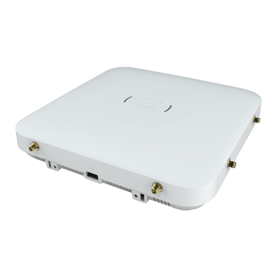
Overview Access Point Features on page 7 AP510i LED Status Indicators on page 9 AP510i Powering Methods on page 10 The AP510i is a next generation, indoor ceiling mount model enterprise class 802.11ax access point (AP). The “i” in AP510i indicates that it comes with internal antennas. The AP features a dual-band radio and comes with eight WiFi internal antennas and one Bluetooth Low Energy (BLE) antenna. - Page 8 Access Point Features Overview Figure 1: Top view of AP510i Figure 2: Side view of AP510i Figure 3: AP510i back ports ExtremeWireless™ AP510i Access Point Installation Guide...
-
Page 9: Ap510I Led Status Indicators
Overview AP510i LED Status Indicators Table 1: AP510i back ports description Callout Description Kensignton lock 12V DC power supply Console port (yellow) LAN 2 (GE) (black) LAN1 (5 GE) (purple) Note On the access point, there is a hole near the Kensington lock in the top-rear that can be used as a provision for safety hanger. -
Page 10: Ap510I Powering Methods
AP510i Powering Methods Overview Figure 4: AP510i LEDs Table 2: AP510i LED status LED icon LED color Description Status Green Normal operational status Amber Non-operational status GE1 Ethernet Amber 100Mbps Green 1000Mbps Purple 2.5G/5G GE2 Ethernet Amber 100Mbps Green 1000MBps Radio#1 Status Green 2.4GHz... -
Page 11: Ap510I Power Table
Overview AP510i Power Table If you need to power the AP510i with an external 12V DC power supply, you can plug the power cord into the power connector on the back of the access point. There is no wall mount bracket for the 12V DC power supply. -
Page 12: Installation Process
One mounting bracket for 802.11ax access point (also called the main mounting bracket) • One AP510i access point • Two Phillips pan-head wood screws • Two screw-in anchors 2. If you find any issues with the access point or the box contents, contact Extreme Networks Support. ExtremeWireless™ AP510i Access Point Installation Guide... -
Page 13: Mount And Connect The Access Point
Installation Process Mount and Connect the Access Point Mount and Connect the Access Point Caution Only qualified personnel must perform installation procedures. Use these instructions as guidelines for mounting and connecting the AP510i easily and safely. The AP510i comes with a mounting bracket (#37201) that can be used to mount the AP on a flat T-bar with flat ceiling tiles, flat surfaces, beams, and some junction boxes. - Page 14 Mounting Brackets and Accessories Usage Installation Process Table 6: Bracket accessory purchase order information (continued) Part number Description BRKT-000147A-01 Beam clip accessory 30525; WS-CAB-RJ45-FLT01 RJ45 flat cable accessory for ceiling mount brackets Table 7: Power supply purchase order information Part number Description 37215 PWR 12V DC, 3A, 2.5 mm X 5.5 mm connector...
- Page 15 Installation Process Mounting Brackets and Accessories Usage Table 9: Bracket and accessory usage for various installation options (continued) Mounting Wall Solid Ceiling Ceiling Junction Beam Ceiling T-bar Notes bracket or install flat install install install tile widths accessory ceiling (protruded install protrusio install...
-
Page 16: Mount The Access Point On A Drywall Or A Wood Wall Or A Solid Flat Ceiling
Mount the Access Point on a Drywall or a Wood Wall or a Solid Flat Ceiling Installation Process Mount the Access Point on a Drywall or a Wood Wall or a Solid Flat Ceiling About This Task The access point is installed on drywall or wood wall or to a solid flat ceiling using: •... - Page 17 Mount the Access Point to a Wall using the Main Installation Process Mounting Bracket Procedure 1. Use the mounting bracket as a template and mark the hole centers on the wall. Figure 5: Main mounting bracket 2. Insert the screws into the holes of the mounting bracket and use the screw-in anchors if needed. 3.
- Page 18 Mount the Access Point to a Wall using the Main Mounting Bracket Installation Process Figure 6: Attaching the access point to the main mounting bracket Callout Description Guide posts to attach the security torx locking screw 5. Attach the security torx locking screw to keep the main mounting bracket in place. For more information, see Install a Security Torx Locking Screw on page 19.
- Page 19 Mount the Access Point to a Wall using the Main Installation Process Mounting Bracket Install a Security Torx Locking Screw Details about how to install the secuirity torx locking screw on the access point. About This Task The security torx locking screw is used to prevent the access point from being removed from the main mounting bracket (#37201).
-
Page 20: Mount The Access Point To A Wall Using An Optional Wall And Box Bracket
Mount the Access Point to a Wall Using an Optional Wall and Box Bracket Installation Process 3. Turn the locking screw into the security screw hole until the security torx locking screw passes through to the other side and touches the screw stop feature. Figure 7: Security torx locking screw stop feature Callout Description... - Page 21 Mount the Access Point to a Wall Using an Optional Wall Installation Process and Box Bracket Figure 8: Mounting the AP using the WS-MBI-WALL04 Bracket • Use the WS-MBI-WALL04 as a template and mark the holes to be used to mount the AP. It is recommended to use the holes marked "A"...
-
Page 22: Mount The Access Point Onto A Wall Using The Main Bracket And The Flat Metal Easy-Attach Adapter
Mount the Access Point onto a Wall Using the Main Bracket and the Flat Metal Easy-Attach Adapter Installation Process Figure 9: Mounting the AP using the WS-MBI-WALL04 Bracket (when bracket corners are broken off) 2. Connect the LAN or Ethernet cable to the AP. 3. - Page 23 Mount the Access Point onto a Wall Using the Main Installation Process Bracket and the Flat Metal Easy-Attach Adapter Procedure 1. Attach the flat metal indoor bracket to the main bracket. Keep the bracket to the center of the main bracket, push and rotate it.
-
Page 24: Mount The Access Point To A Wall Using The Phillips Pan-Head Screws
Mount the Access Point to a Wall Using the Phillips Pan- Head Screws Installation Process Mount the Access Point to a Wall Using the Phillips Pan-Head Screws About This Task You can mount the access point directly onto a drywall or a solid wall using the Phillips pan-head screws. -
Page 25: Mount The Access Point To A Suspended Or Drop Ceiling
Installation Process Mount the Access Point to a Suspended or Drop Ceiling Mount the Access Point to a Suspended or Drop Ceiling About This Task For suspended ceiling or drop ceiling installation, the main mounting bracket is used directly on the T- bar. - Page 26 Mount the Access Point Using the Main Mounting Bracket to a Flat T-bar Installation Process Procedure 1. Remove the ceiling tiles, push and rotate the main mounting bracket onto the T-bar in such a way that the center angled locking tabs of the main bracket gets attached to the T-bar. Figure 12: Attach the main mounting bracket to a T-bar 2.
-
Page 27: Mount The Access Point Using The Main Mounting Bracket And Kt-135628-01 Adapter To A Flat T-Bar
Mount the Access Point Using the Main Mounting Installation Process Bracket and KT-135628-01 Adapter to a Flat T-bar Mount the Access Point Using the Main Mounting Bracket and KT-135628-01 Adapter to a Flat T-bar About This Task Mounting the AP to a suspended or a drop ceiling requires the optional adaptor (Universal Mounting Kit for WLAN APs;... - Page 28 Mount the Access Point Using the WS-MBI-DCFLUSH Bracket to a Flat T-bar Installation Process 2. Open the movable sliding part of the bracket to give the stationary and slider T-bar more space. Figure 13: Install the WS-MBI-DCFLUSH bracket Callout Description T-bar Movable sliding part of the DC-FLUSH bracket 3.
-
Page 29: Mount The Access Point Using The Ws-Mbi-Dcmtr01 Bracket
Mount the Access Point Using the WS-MBI-DCMTR01 Installation Process Bracket 6. Slide the T-bar ceiling mount bracket base into the back of the access point. The locking tab fits into a groove in the outside of the AP. Figure 14: Attach the AP unit onto the WS-MBI-DCFLUSH bracket 7. - Page 30 Mount the Access Point Using the WS-MBI-DCMTR01 Bracket Installation Process • T-bar can have a maximum protrusion of 0.625 in. (15.8 mm) • Maximum protrusion of the ceiling tile can be 0.625 in. (15.8 mm). 1 Remove the ceiling panels around the drop ceiling T-bar rail Procedure 1.
-
Page 31: Mount The Access Point To A Junction Box
Installation Process Mount the Access Point to a Junction Box 6. Slide the T-bar ceiling mount bracket base into the back of the access point. The locking tab fits into a groove in the outside of the AP. Figure 16: Attach the AP unit onto the WS-MBI-DCMTR01 bracket 7. -
Page 32: Mount The Access Point To A Beam
Mount the Access Point to a Beam Installation Process Procedure 1. Remove the screws holding the junction box coverplate and remove the LAN cable from the coverplate if necessary. 2. Line up the bracket holes on the junction box and ensure that they align. If the holes do not align, then use the WS-MBI-WALL04 bracket. - Page 33 Installation Process Mount the Access Point to a Beam 4. Use the screw and clamp on the top of the adapter to secure the AP in place on the beam. 5. Insert the Ethernet plug into the AP. ExtremeWireless™ AP510i Access Point Installation Guide...
-
Page 34: Specifications
Specifications Product specifications for the AP510i indoor access point. Table 10: Product specifications Part Number: AP510i-FCC Cloud-ready, Dual 5GHz, Dual Band, Sensor radio, Dual Radio 802.11ax/ac/abgn, 4x4:4 MIMO Indoor 11ax access point. Internal Antenna. Domain: US, Peurto Rico, and Columbia Part Number: AP510i-WR Cloud-ready, Dual 5GHz, Dual Band, Sensor radio, Dual Radio 802.11ax/ac/abgn, 4x4:4 MIMO Indoor... -
Page 35: Antenna Information
Antenna Information Internal Antenna Access Point The AP510i is an indoor access point with eight WiFi internal antennas and one BLE internal antenna. Table 12: AP510i internal antenna Access point Application Description Gain (dBi) Frequency Connector model (GHz) AP510i Indoor MIMO 4 dBi 2.4 GHz... -
Page 36: Antenna Patterns - 2.4 Ghz
Antenna Patterns - 2.4 GHz Antenna Information Antenna Patterns - 2.4 GHz Figure 17: Horizontal Radiation Pattern 2.4 GHz ExtremeWireless™ AP510i Access Point Installation Guide... - Page 37 Antenna Information Antenna Patterns - 2.4 GHz Figure 18: Vertical Radiation Pattern 2.4 GHz ExtremeWireless™ AP510i Access Point Installation Guide...
-
Page 38: Antenna Patterns - 5 Ghz
Antenna Patterns - 5 GHz Antenna Information Antenna Patterns - 5 GHz Figure 19: Horizontal Radiation Pattern 5GHz - Radio 1 ExtremeWireless™ AP510i Access Point Installation Guide... - Page 39 Antenna Information Antenna Patterns - 5 GHz Figure 20: Vertical Radiation Pattern 5GHz - Radio 1 ExtremeWireless™ AP510i Access Point Installation Guide...
- Page 40 Antenna Patterns - 5 GHz Antenna Information Figure 21: Horizontal Radiation Pattern 5 GHz - Radio 2 ExtremeWireless™ AP510i Access Point Installation Guide...
- Page 41 Antenna Information Antenna Patterns - 5 GHz Figure 22: Vertical Radiation Pattern 5GHz - Radio 2 Table 13: Maximum antenna gain for integrated antenna Software Mode Radio 1 Radio 2 IoT Radio Mode 1 4dBi; 2.4GHz 6dBi; 5GHz 5dBi Mode 2 4dBi;...
-
Page 42: Regulatory And Compliance Information
Regulatory and Compliance Information Safety Guidelines on page 42 Federal Communications Commission (FCC) Notice on page 42 Industry Canada Notice on page 43 Brazil Agência Nacional De Telecomunicações (Anatel) Statement on page 44 Hazardous Substances on page 44 Supplement to Product Instructions on page 45 NCC Statement on page 45... -
Page 43: Industry Canada Notice
Regulatory and Compliance Information Industry Canada Notice reception, which can be determined by turning the equipment off and on, the user is encouraged to try to correct the interference by one of the following measures: • Reorient or relocate the receiving antenna. •... -
Page 44: Brazil Agência Nacional De Telecomunicações (Anatel) Statement
Brazil Agência Nacional De Telecomunicações (Anatel) Statement Regulatory and Compliance Information Warning IC Radiation Exposure Statement: This equipment complies with ISED radiation exposure limits set forth for an uncontrolled environment. This equipment should be installed and operated with minimum distance 26cm between the radiator & your body. Warning Déclaration d'exposition aux radiations: Cet équipement est conforme aux limites d'exposition aux rayonnements ISED établies pour un environnement non contrôlé. -
Page 45: Supplement To Product Instructions
Regulatory and Compliance Information Supplement to Product Instructions Supplement to Product Instructions NCC Statement ExtremeWireless™ AP510i Access Point Installation Guide... -
Page 46: Ce Information
CE Information Regulatory and Compliance Information CE Information CE Information The device is restricted to indoor use only when operating in the 5150 to 5350 MHz frequency range. All Operational Modes 2.4GHz: 802.11b, 802.11g, 802.11n (HT20), 802.11n (HT40), 802.11ax (HEW20), 802.11ax (HEW40), 802.15.4 (Thread), Bluetooth (LE) 5GHz: 802.11a, 802.11n (HT20), 802.11n (HT40), 802.11ac (VHT20), 802.11ac (VHT40), 802.11ac (VHT80), 802.11ac (VHT160), 802.11ax (HEW20), 802.11ax (HEW40), 802.11ax (HEW80), 802.11ax (HEW160) -
Page 47: Declaration Of Conformity In Languages Of The European Community
Declaration of Conformity in Languages of the Regulatory and Compliance Information European Community 3. It has been determined by the European Parliament that there are potential negative effects on the environment and human health as a result of the presence of hazardous substances in electrical and electronic equipment. - Page 48 Declaration of Conformity in Languages of the European Community Regulatory and Compliance Information Italian Con la presente dichiara che questo Radio LAN device (AP510i) è conforme ai requisiti essenziali ed alle altre disposizioni pertinenti stabilite dalla direttiva 2014/53/EU. Spanish Por medio de la presente declara que el Radio LAN device (AP510i) cumple con los requisitos esenciales y cualesquiera otras disposiciones aplicables o exigibles de la Directiva 2014/53/EU.
-
Page 49: Index
Index accessories usage 13 LEDs antenna information LED description 9 antenna pattern 35, 36, 38 status indicator 9 antenna usage 35, 36, 38 AP510i accessories 13 AP510i bracket 13 mount the access point connect the access point 13 mounting bracket 13 bracket usage 13 NCC Statement 45 CE Information, Regulatory 46 ceiling mount 25 power connection 10, 11 powering methods 10, 11 datasheet 34...