Table of Contents
Advertisement
Quick Links
Dear Customer,
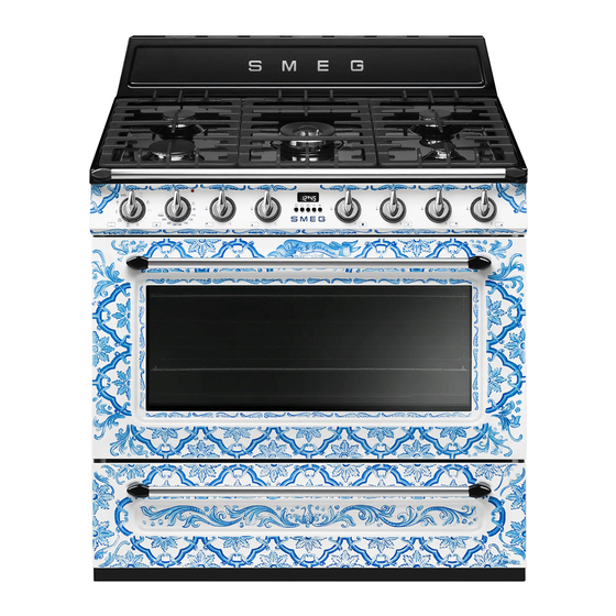
Thank you for having chosen Divina Cucina, domestic appliances from the 'Sicily is my
love' collection by Smeg – Dolce&Gabbana.
By choosing this product, you have selected an appliance
that combines the quality and technology of Smeg products and the creativity and design of
Dolce&Gabbana.
The decorations are applied to the product through a combination of patented industrial
and manual process
so any irregularities in the processing should be considered as unique and distinctive
characteristics of the product.
Advertisement
Table of Contents

Related Manuals for Smeg Dolce&Gabbana Divina Cucina TRA90DGM9


Summary of Contents for Smeg Dolce&Gabbana Divina Cucina TRA90DGM9
- Page 1 Smeg – Dolce&Gabbana. By choosing this product, you have selected an appliance that combines the quality and technology of Smeg products and the creativity and design of Dolce&Gabbana. The decorations are applied to the product through a combination of patented industrial...
-
Page 2: Table Of Contents
5.5 Electrical connection 5.6 Instructions for the installer TRANSLATION OF THE ORIGINAL INSTRUCTIONS We advise you to read this manual carefully, which contains all the instructions for maintaining the appliance’s aesthetic and functional qualities. For further information on the product: www.smeg.com... -
Page 3: Instructions
Instructions 1 Instructions • Cleaning and maintenance must not be carried out by unsupervised 1.1 General safety instructions children. • Make sure that the flame-spreader Risk of personal injury crowns are correctly positioned in • During use the appliance and its their housings with their respective accessible parts become very hot. - Page 4 Instructions • If you need to move food or at the • Do not try to repair the appliance end of cooking, open the door 5 yourself or without the intervention cm for a few seconds, let the of authorised persons. steam come out, then open it fully.
- Page 5 Instructions • Danger of fire: do not store items • Take care not to spill acidic on the cooking surfaces. substances such as lemon juice or vinegar onto the cooktop. • DO NOT USE THE APPLIANCE AS A SPACE HEATER. •...
-
Page 6: Manufacturer's Liability
Instructions Installation • Have the electrical connection performed by authorised persons. • THIS APPLIANCE MUST NOT BE • The appliance must be connected INSTALLED IN BOATS OR to earth in compliance with CARAVANS. electrical system safety standards. • The appliance must not be installed •... -
Page 7: Appliance Purpose
Instructions 1.3 Appliance purpose 1.6 To save energy • This appliance is intended for • Only preheat the appliance if the recipe requires you to do so. cooking food in the home • Unless otherwise indicated on the environment. Every other use is package, defrost frozen foods considered improper. -
Page 8: How To Read The User Manual
Instructions 1.7 How to read the user manual This user manual uses the following reading conventions: Instructions General information on this user manual, on safety and final disposal. Description Description of the appliance and its accessories. Information on the use of the appliance and its accessories, cooking advice. -
Page 9: Description
Description 2 Description 2.1 General Description 1 Upstand 6 Door 2 Hob 7 Fan 3 Control panel 8 Storage compartment 4 Oven light Rack/tray support frames 5 Seal... -
Page 10: Hob
Description 2.2 Hob AUX = Auxiliary R = Rapid SR = Semi-rapid DUAL = Ultra rapid 2.3 Control panel 1 Function knob 3 Indicator light The oven’s various functions are suitable for When flashing, it indicates that the different cooking modes. After selecting the appliance is heating up to reach the set required function, set the cooking temperature. -
Page 11: Other Parts
Description 4 Hob burner knobs Shelves For lighting and adjusting the hob burners. The appliance features shelves to position trays and racks at different heights. The Press and turn the knobs anti-clockwise to insertion heights are indicated from the in order to light the relative burners. Turn the bottom upwards (see 2.1 General knobs to the zone between the maximum Description). - Page 12 Description Tray rack Rack To be placed over the top of the oven tray; Useful for supporting containers with food for cooking foods which may drip. during cooking. Deep tray Some models are not provided with all accessories. The accessories intended to come into contact with food are made of materials that comply with the provisions of current legislation.
-
Page 13: Use
3 Use High temperature inside the storage compartment Instructions Danger of burns High temperature inside the oven • Do not open the storage compartment during use when the appliance is on and still hot. Danger of burns • The items inside the storage compartment could be very hot after •... - Page 14 Malfunctions High temperature inside the storage compartment Any of the following indicate a malfunction and you should contact a service centre. Danger of fire or explosion • Yellowing of the burner plate. • Do not spray any spray products near •...
-
Page 15: To Save Energy
3.1 To save energy 3.2 Using the accessories • Only preheat the appliance if the recipe Trivets and reduction pan supports requires you to do so. The trivets and reduction pan supports must • Unless otherwise indicated on the be placed on the hob pan supports. Make package, defrost frozen foods before sure they are placed properly. - Page 16 Racks and trays Rotisserie Racks and trays have to be inserted into the 1. Insert the 4 supplied bushings in the 4 side guides until they come to a complete corner holes of the deep tray and stop. screw them onto the ring nuts with a suitable tool (such as a screwdriver).
- Page 17 3. Prepare the rotisserie rod with the food 5. Place the tray on the first runner (see using the clip forks provided. The clip “General Description”). forks can be tightened using the 6. Insert the tip of the rod in the rotisserie fastening screws.
-
Page 18: Using The Hob
7. To activate the rotisserie, turn the 3.3 Using the hob All the appliance’s control and monitoring function knob to the position and devices are located together on the front set the cooking temperature using the panel. The burner controlled by each knob is temperature knob. -
Page 19: Using The Storage Compartment
3.4 Using the storage compartment Correct positioning of the flame- spreader crowns and burner caps There is a storage compartment located at the bottom of the cooker; this can be used Before lighting the hob burners, make sure to store pans or metal objects required for that the flame-spreader crowns are its use. - Page 20 Functions list Convection Grill As the heat comes from above and The heat coming from the grill element gives perfect grilling results below at the same time, this system above all for thin and medium is particularly suitable for certain thickness meat and, in combination types of food.
- Page 21 Fan forced The combination of the fan and the This function is particularly suitable circulaire heating element for cooking on a single shelf with (incorporated in the rear of the low energy consumption. oven) allows you to cook different Ideal for cooking meat, fish and foods on several levels, as long as vegetables.
-
Page 22: Cooking Advice
3.6 Cooking advice • When using the Grill function, we recommend that you turn the temperature General advice knob to the maximum setting symbol • Use a fan assisted function to achieve in order to optimise cooking. consistent cooking at several levels. •... -
Page 23: Programmer Clock
3.7 Programmer clock Advice for defrosting and proving • Place frozen foods without their packaging in a lidless container on the first shelf of the oven. • Avoid overlapping the food. • To defrost meat, use the rack placed on the second level and a tray on the first level. - Page 24 Setting the time Timed cooking Timed cooking is the function If the time is not set, the oven will which allows a cooking operation not switch on. to be started and then ended after a specific length of time set by the On the first use, or after a power failure, the user.
- Page 25 6. Press the buttons at the 3. Use the button to set the required minutes. same time to reset the programmer clock. 4. Wait approx. 5 seconds without pressing It is not possible to set a cooking any button in order for the function to time of more than 10 hours.
- Page 26 Adjusting the buzzer volume Minute minder timer The buzzer volume can be set to 3 different The minute minder timer does not levels. When the buzzer is in operation, stop the cooking operation but press the button to change the setting. rather informs the user when the set time has run out.
- Page 27 Cooking information table Weight Temp. Time Food Function Shelf (minutes) (Kg) (°C) Lasagne 3 - 4 Convection 220 - 230 45 - 50 Pasta bake 3 - 4 Convection 220 - 230 45 - 50 Veal roast Fan forced/Fan assisted 180 - 190 90 - 100 Pork loin...
-
Page 28: Cleaning And Maintenance
4 Cleaning and maintenance How to maintain the surface finish of your exclusive Instructions SMEG – DOLCE&GABBANA appliance Improper use Use only a soft, dry cloth to dust the Risk of damage to surfaces surfaces of the appliance. For residues that... -
Page 29: Cleaning The Hob
Cleaning and maintenance 4.1 Cleaning the hob Igniters and thermocouples For correct operation the igniters and Cooking hob pan support grids thermocouples must always be perfectly Remove the pan support grids and clean clean. Check them frequently and clean them in lukewarm water and non-abrasive them with a damp cloth if necessary. -
Page 30: Cleaning The Door
Cleaning and maintenance 4.2 Cleaning the door 3. To reassemble the door, put the hinges in the relevant slots in the oven, making sure Removing the door that grooved sections A are resting For easier cleaning it is recommended to completely in the slots. - Page 31 Cleaning and maintenance Removing the internal glass panes 5. Remove the intermediate glass pane by lifting it upwards. For easier cleaning the internal glass panes of the door can be removed. 1. Open the door. 2. Position the retaining clips in the holes in the hinges in order to prevent accidental closing of the door.
-
Page 32: Cleaning The Oven Cavity
Cleaning and maintenance 4.3 Cleaning the oven cavity Removing racks/trays support frames In order to keep your oven in the best Removing the guide frames enables the possible condition, clean it regularly after sides to be cleaned more easily. This letting it cool down. -
Page 33: Vapor Clean
Cleaning and maintenance 4.4 Vapor Clean Cleaning the top section The oven cavity is fitted with a tilting heating Vapor Clean is an assisted element which facilitates cleaning the top cleaning procedure which part (roof) of the oven. facilitates the removal of dirt. 1. - Page 34 Cleaning and maintenance • Pour approximately 40 cc of water into Vapor Clean cycle setting the tray. Make sure it does not overflow 1. Set a cooking time of 18 minutes using out of the cavity. the programmer clock. 2. Turn the function knob to the symbol and the temperature knob to the symbol.
-
Page 35: Extraordinary Maintenance
Cleaning and maintenance 4.5 Extraordinary maintenance 4. Slide out and remove the light bulb. Replacing the internal light bulb Live parts Danger of electrocution • Unplug the appliance. The oven is fitted with a 40W light Do not touch the halogen light bulb. - Page 36 Cleaning and maintenance Installing and removing the seal What to do if... To remove the seal: The appliance is not working properly: • Unhook the clips located in the 4 corners • The switch is defective: check the fuse and in the centre, then pull the seal box to see whether the switch is in outwards.
-
Page 37: Installation
Installation 5 Installation 5.2 Gas connection Gas leak 5.1 Minimum clearance to Danger of explosion combustible surfaces Freestanding cooker • After carrying out any operation, check that the tightening torque of gas connections is between 10 Nm and 15 • If required, use a pressure regulator that complies with current regulations. - Page 38 Installation Connection of the appliance to the gas U.L.P.G. Can be connected to the inlet supply must be in accordance with the fitting directly. The pressure must be requirements of AS5601. A ½” BSP checked to ensure it is operating at connector at the inlet is recommended and 2.75kPa.
-
Page 39: Adaptation To Different Types Of Gas
Installation 5.3 Adaptation to different types of or via forced extraction. An efficient extraction system requires precision planning by a specialist qualified in this In case of operation with other types of gas, area and must comply with the positions the burner nozzles must be changed and the and clearances indicated by the applicable minimum flame adjusted on the gas cocks. - Page 40 Installation 3. Replace the burners in their respective Adjusting the minimum setting for LPG housings. Tighten the screw located at the side of the cock spindle clockwise all the way. Adjusting the minimum setting for natural or city gas Following adjustment to a gas Light the burner and turn it to the minimum other than the one originally set in position.
-
Page 41: Positioning
Installation Burner and nozzle characteristics table 1 ULPG 2.75 kPa DUAL int. DUAL ext. Nominal gas consumption (MJ/h) 10.8 Injector (1/100 mm) 0.54 0.68 0.88 0.48 1.00 2 NG 1.0 kPa DUAL int. DUAL ext. Nominal gas consumption (MJ/h) Injector (1/100 mm) 1.20 1.55 0.81... - Page 42 Installation Appliance overall dimensions 900 mm 600 mm B - Class 2 subclass 1 min. 150 mm (Built-in appliance) 900 - 915 mm 750 mm 450 mm 900 mm Minimum distance from side walls or other flammable material. Minimum cabinet width (=A). C - Class 2 subclass 1 (Built-in appliance) The appliance must be installed by...
- Page 43 Installation Appliance dimensions Fastening to the wall with brackets Position of gas and electrical connections. The anti-tip devices must be installed in order to prevent the appliance from tipping over. 1. Screw the wall fastening plate to the rear of the appliance. Positioning and levelling Heavy appliance Risk of damage to the appliance...
- Page 44 Installation 3. Assemble the fastening bracket. 5. Align the base of the fastening bracket with the ground and tighten the screws to fix the measurements. 6. Use 50 mm for the distance from the 4. Align the base of the hook on the side of the appliance to the bracket fastening bracket with the base of the holes.
- Page 45 Installation 7. Move the bracket onto the wall and Assembling the upstand mark the position of the holes to be The upstand provided is an drilled in the wall. integral part of the product. It must be fastened to the appliance prior to installation.
-
Page 46: Electrical Connection
Installation 5.5 Electrical connection Mounting the plinth The plinth provided is an integral Power voltage part of the product; it must be Danger of electrocution fastened to the appliance prior to installation. • Have the electrical connection performed by authorised technical The plinth must always be positioned and personnel. -
Page 47: Instructions For The Installer
Installation 5.6 Instructions for the installer The appliance can work in the following modes: • The plug must be accessible after • 220-240 V 1N~ installation. Do not bend or trap the power cable. • The appliance must be installed according to the installation diagrams. - Page 51 914779526/A...