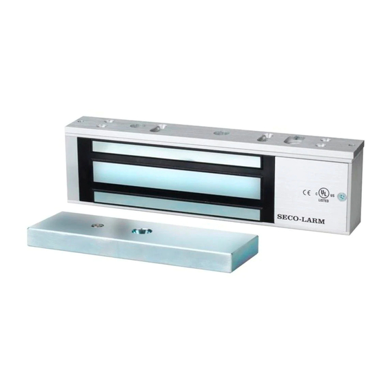
SECO-LARM E-941SA-600 Manual
Electromagnetic lock
Hide thumbs
Also See for E-941SA-600:
- Manual (9 pages) ,
- Installation manual (5 pages) ,
- Installation manual (2 pages)

Related Manuals for SECO-LARM E-941SA-600


Summary of Contents for SECO-LARM E-941SA-600
- Page 1 Electromagnetic Lock E-941SA-600 / E-941SA-1200 Manual Identification of: NFPA Standards 70 and 72 ®...
-
Page 2: Parts List
Features: MOV surge protection. The power for the E-941SA-600 / E-941SA-1200 is to Adjustable mounting bracket. be provided by a Listed (UL294, UL603 and CAN/UL C-S533, also UL864 or UL1481 for standalone power Complete mounting hardware for typical supply) Class 2 Power Supply. -
Page 3: Installation Applications
Use the diagram below to help decide whether or not an optional bracket will be necessary for installation. Typical "L" Bracket Installation "L"-Bracket and "U" Bracket "Z"-Bracket (Typically for glass doors) SECO-LARM U.S.A., Inc. -
Page 4: Installation Notes
3. The most suitable mounting location for the electromagnetic lock may require the use of additional SECO-LARM accessories such as Z-brackets, and L-brackets. Please see the diagram on page 3 to decide if a particular application requires any mounting accessories. - Page 5 Keeping them loose will allow for adjustment of the plate left or right so that the mounting plate and the armature plate form a 90-degree angle. See the diagram below. 90° Mounting Plate E-941SA-1200 mounting plate E-941SA-600 mounting plate Armature Plate SECO-LARM U.S.A., Inc.
- Page 6 Connect the power wires according to the wiring diagram on page 7. Test the unit. Then replace the front cover and install the hex-head tamper caps. NOTE: This should be the very last step, as once the tamper caps are in place they are very difficult to remove. SECO-LARM U.S.A., Inc.
-
Page 7: Wiring Diagram
*NOTE: Connect switching devices like push-to-exit switches between the power source and the positive terminal on the lock. Connecting switching devices to the negative terminal may cause a delay in unlocking. Maximum Distance from Power Source to Electromagnetic Lock: For a complete chart, please visit www.seco-larm.com 12VDC Minimum Wire Gauge: Wire Length 25ft. - Page 8 LIFETIME LIMITED WARRANTY This SECO-LARM product is warranted against defects in material and workmanship while used in normal service for the lifetime of the product. SECO-LARM’s obligation is limited to the repair or replacement of any defective part if the unit is returned, transportation prepaid, to SECO-LARM.