Advertisement
Quick Links
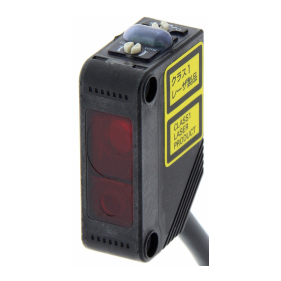
Laser Photoelectric Sensor with Built-in Amplifier
E3Z-LT/LR/LL
The Most Compact Laser Sensor
The Most Reliable E3Z
■ Excellent quality of E3Z such as the maximum ambient operating
temperate of 55°C, IP67 degree of protection is inherited.
■ Safe and reliable class 1 (JIS/IEC) laser used
■ Excellent detection performance supporting long distance and
low hysteresis
■ Complete Compliance with RoHS
■ Spot diameters can be customized.
Increasing the spot diameter makes optical axis adjustment easier.
Be sure to read Safety Precautions on
page 9.
Applications
Detect the sides of large tiles.
Greatly Enhanced Beam Visibility
for Easier Optical Axis Adjustment of Sensors
Detect chip components on tape.
Optical Customization for E3Z Lasers
That Fit the Application!
The E3Z laser system has an original modular structure. Spot diameters can be customized, as shown in the examples below.
For example, when a through-beam model is used at far range, the optical axis can be easily adjusted by widening the spot, and minute objects
can be easily detected by minimizing the spot at close range. These applications improve product value.
Advanced Optical Technology of the E3Z Laser
Laser beam directional deviation can be suppressed and
spot diameters can be freely customized.
This is achieved through high-precision alignment technology based on LD
and emitter lens modularization.
The lens position can be adjusted inline.
http://www.ia.omron.com/
Long-distance Sensing
at 300 mm (White Paper)
(P atent pending .)
Count bottles.
Reliable Detection of
Small Objects and
Narrow Gaps with the Small Spot
Detect protruding straws.
Laser Modular Conceptual Diagram
Laser beam
By precisely adjusting the emitter lens in the vertical, horizontal, and depth directions,
alignment can be achieved with minimal directional deviation (to ±1 degree).
(c)Copyright OMRON Corporation 2007 All Rights Reserved.
A Low Black/White Error for
Applications with Mixed Colors
Holder
LD (semiconductor laser)
Emitter lens
1
Advertisement

Related Manuals for Omron E3Z-LT


Summary of Contents for Omron E3Z-LT
- Page 1 The lens position can be adjusted inline. (P atent pending .) By precisely adjusting the emitter lens in the vertical, horizontal, and depth directions, alignment can be achieved with minimal directional deviation (to ±1 degree). http://www.ia.omron.com/ (c)Copyright OMRON Corporation 2007 All Rights Reserved.
- Page 2 • Pre-wired Connector Models with M8 4-pin connectors, M8 3-pin connectors, or e-CON connectors. *4. Consult with your OMRON representative if a distance of more than 10 m is required. Models with large custom-size spots can be produced. These make optical axis adjustment easier and allow the beam to be received more stably by the Receiver even if vibration is present.
- Page 3 Connectors of Both Ends 0.5 to 1 m E39-ECONW@M 1.1 to 1.5 m Replace the box (@) in the model number by the cable length in increments of 0.1 m. 1.6 to 2 m http://www.ia.omron.com/ (c)Copyright OMRON Corporation 2007 All Rights Reserved.
- Page 4 Note: An emission stop function can be added to Through-beam Models as a custom function. Ask your OMRON representative for details. * Consult with your OMRON representative if a distance of more than 10 m is required. Models with large custom-size spots can be produced. These make optical axis adjustment easier and allow the beam to be received more stably by the Receiver even if vibration is present.
- Page 5 Setting: Setting: Setting: Setting: Setting: Setting: Setting: Setting: 300 mm 160 mm 40 mm 40 mm 300 mm 100 mm 40 mm 40 mm http://www.ia.omron.com/ (c)Copyright OMRON Corporation 2007 All Rights Reserved.
- Page 6 − θ −15 −15 − θ Sensing Sensing Center Center object object −20 line line −20 −40 −30 −20 −10 −40 −30 −20 −10 Inclination angle θ (°) Inclination angle θ (°) http://www.ia.omron.com/ (c)Copyright OMRON Corporation 2007 All Rights Reserved.
- Page 7 Pin Arrangement Pin Arrangement indicator Pin Arrangement (orange) Press fit D side Dark-ON Output (DARK ON) transistor Load Operate (e.g., relay) Pin 2 is not used. Reset (Between blue and black leads) http://www.ia.omron.com/ (c)Copyright OMRON Corporation 2007 All Rights Reserved.
- Page 8 XS2F-D421-DC0-A XS2F-D422-DC0-A Black Output XS2F-D421-GC0-A XS2F-D422-GC0-A Note: 1. Pin 2 is not used. 2. The above M8 and M12 Connectors made by OMRON are IP67. Nomenclature Sensors with Sensitivity Adjustment and Distance-settable Sensor Mode Selector Switch BGS Models E3Z-LL@@ Through-beam Models...
- Page 9 Sensor may become loose due to vibration. The appropriate tightening torque is 0.3 to 0.4 N·m. If other commercially available connectors are used, follow the recommended connector application conditions and recommended tightening torque specifications. http://www.ia.omron.com/ (c)Copyright OMRON Corporation 2007 All Rights Reserved.
- Page 10 Moving Moving direction direction Moving direction Install the Sensor as shown in the following illustration if each sensing object greatly differs in color or material. Incorrect Correct Moving direction Moving direction http://www.ia.omron.com/ (c)Copyright OMRON Corporation 2007 All Rights Reserved.
- Page 11 15.5 3.5 dia. Two, 10.4 M8 connector 9.75 12.45 Operation indicator (orange) 10.8 10.4 Receiver Operation selector Stability indicator (green) Sensitivity adjuster Lens Optical axis 25.4 15.5 Two, 10.4 M8 connector 9.75 http://www.ia.omron.com/ (c)Copyright OMRON Corporation 2007 All Rights Reserved.
- Page 12 Standard Connector Operation indicator Models (orange) E3Z-LR66 E3Z-LR86 10.8 10.4 Operation selector Stability indicator (green) Sensitivity adjuster Lens Receiver Optical axis 19.5 4 25.4 15.5 10.4 Emitter Two, M3 M8 connector 9.75 http://www.ia.omron.com/ (c)Copyright OMRON Corporation 2007 All Rights Reserved.
- Page 13 E3Z-LL68 E3Z-LL88 10.8 10.4 Distance adjuster Operation selector Stability indicator (green) Receiver lens (7.0 dia.) Emitter lens (2.5 dia.) Receiver Optical axis 10 4 25.4 13.5 Two, 10.4 Emitter M8 connector 9.75 http://www.ia.omron.com/ (c)Copyright OMRON Corporation 2007 All Rights Reserved.
- Page 14 Two, 3.4 dia. Materials Materials Reflector: Polycarbonate (surface) Reflective surface: Acrylic Acrylic (interior) Rear surface: Frame: Cat. No. E850-E1-01 In the interest of product improvement, specifications are subject to change without notice. http://www.ia.omron.com/ (c)Copyright OMRON Corporation 2007 All Rights Reserved.
- Page 15 (2) Do not use the Sensor in environments where the cables may become immersed in oil or other liquids or where liquids may penetrate the Sensor. Doing so may result in damage from burning and fire, particularly if the liquid is flammable. http://www.ia.omron.com/ (c)Copyright OMRON Corporation 2007 All Rights Reserved.
- Page 16 Receiver. Sensor sensing distance.) (Light may enter even if the Sensors are separated by Sensor Sensor more than the sensing distance.) θ θ Adjust the Lowering the sensitivity will generally help. sensitivity. http://www.ia.omron.com/ (c)Copyright OMRON Corporation 2007 All Rights Reserved.
- Page 17 Repeated Bending other terminals. Normally, the Sensor cable should not be bent repeatedly. (For bending-resistant cable, see Attachment to Moving Parts page C-4.) http://www.ia.omron.com/ (c)Copyright OMRON Corporation 2007 All Rights Reserved.
- Page 18 Approx. 13,000 times Approx. 500,000 times The testing conditions of the standard cable and robot cable are different. Refer to the values in the above table to check bend-resistant performance under actual working conditions. http://www.ia.omron.com/ (c)Copyright OMRON Corporation 2007 All Rights Reserved.
- Page 19 Locked position Note:1.To maintain the fiber characteristics, make sure that the lock is released before removing the fibers. 2. Lock and unlock the fibers at an ambient temperature of − 10 to 40°C. http://www.ia.omron.com/ (c)Copyright OMRON Corporation 2007 All Rights Reserved.
- Page 20 (height) detection data, and selection list for specifications. Cleaning • Keep organic solvents away from the Sensor. Organic solvents will dissolve the surface. • Use a soft, dry cloth to clean the Sensor. http://www.ia.omron.com/ (c)Copyright OMRON Corporation 2007 All Rights Reserved.
- Page 21 Warranty and Limitations of Liability WARRANTY OMRON's exclusive warranty is that the products are free from defects in materials and workmanship for a period of one year (or other period if specifi ed) from date of sale by OMRON. OMRON MAKES NO WARRANTY OR REPRESENTATION, EXPRESS OR IMPLIED, REGARDING NON-INFRINGEMENT, MERCHANTABILITY, OR FITNESS FOR PARTICULAR PURPOSE OF THE PRODUCTS.