Table of Contents

Related Manuals for Invacare Formula CG Tilt


Summary of Contents for Invacare Formula CG Tilt
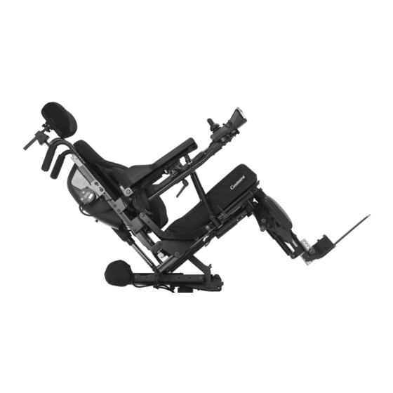
- Page 1 Invacare® Formula™ CG Seating en Power Wheelchair Seat: Tilt, Recline, Elevate, Tilt/Recline User Manual This manual MUST be given to the user of the product. BEFORE using this product, read this manual and save for future reference.
- Page 2 All rights reserved. Republication, duplication or modification in whole or in part is prohibited without prior written permission from Invacare. Trademarks are identified by ™and ®. All trademarks are owned by or licensed to Invacare Corporation or its subsidiaries unless otherwise noted.
-
Page 3: Table Of Contents
4 Label Locations ........26 Contents 4.1 All Wheelchairs ....... . 26 5 Technical Data . - Page 4 6.8.2 Speed Control ......40 7.7.2 Removing ........54 6.8.3 Joystick .
- Page 5 7.19 Adjusting the Height of the Manual Center Mount 7.33.1 Removing ....... . . 77 Footrest .
-
Page 6: General
Invacare® Formula™ CG Seating 1.2 Reference Documents 1 General Refer to the wheelchair base user manual for additional safety and operation information. 1.1 Symbols Signal symbols and/or words are used in this manual and apply to Refer to the table below for part numbers of additional hazards or unsafe practices which could result in personal injury or documents which are referenced in this manual. - Page 7 Risk of Serious Injury or Damage contact a qualified technician or Invacare for repair. Loss of power due to loose electrical connections could cause the wheelchair to suddenly stop resulting in WARNING! serious injury or damage.
- Page 8 – If Sip n’ Puff does not function properly, inspect system for blockages, clogged saliva trap or air leaks. As necessary, replace mouthpiece, breath tube and saliva trap. Contact your Invacare dealer/provider for more information about maintaining and troubleshooting the Sip n’ Puff system. 1143155-R-01...
- Page 9 7176–14:2008. Risk of Injury, Damage or Death Exposure to liquids may cause injury, damage or death. Invacare has tested its power wheelchairs in accordance – DO NOT expose electrical connections to sources of with RESNA Section 9 “Rain Test”. liquid or dampness. This includes, but is not limited to, water, body fluids or cleaning agents.
-
Page 10: Set Up
WARNING! turn the wheelchair Off immediately and reenter set Risk of Serious Injury up specifications. Contact Invacare, if wheelchair still Sharp edges can cause serious injury. does not perform to correct specifications. – Be mindful that some parts may have sharp edges. Use caution when encountering these sharp edges. -
Page 11: Transport In Vehicles
– Replace any damaged cords immediately. – Contact Invacare Corporation with any questions about using this wheelchair for seating in a motor 1.6.2 Transport in Vehicles vehicle. - Page 12 Risk of Injury, Damage or Death available by the auto industry. Invacare cannot and does not Damaged parts due to collision or impact may result recommend any wheelchair transportation system.
- Page 13 – Use both pelvic and upper torso belts. information or to answer questions regarding TRRO. – The pelvic belt that is provided by Invacare has been tested for use in a motor vehicle on this wheelchair As of this date, the Department of Transportation has only.
-
Page 14: Powered Seating
Invacare® Formula™ CG Seating 1.6.3 Powered Seating WARNING! Risk of Death or Serious Injury WARNING! Operating the wheelchair with the seat – This seating system has been custom designed and tilted/reclined/back angle position beyond 20° will be assembled to the wheelchair base before can cause instability resulting in death or serious injury delivery to the user. -
Page 15: Repair Or Service Information
– Qualified technician MUST setup, service and program could cause a fire, death, physical injury or property the wheelchair. damage. If such devices are used, Invacare shall not be – DO NOT allow non-qualified individuals to perform liable and the limited warranty is void. - Page 16 Invacare® Formula™ CG Seating DANGER! Risk of Death, Serious Injury, or Damage Corroded electrical components due to water and/or liquid exposure, or incontinent users can result in death, serious injury, or damage. – Minimize exposure of electrical components to water and/or liquids.
-
Page 17: Safety Handling
Safety Handling 2 Safety Handling WARNING! Risk of Injury, Damage or Death Use of the wheelchair while judgement or ability is 2.1 Safety and Handling impaired may result in injury, damage or death. Refer to wheelchair base user manual for additional safety –... - Page 18 Invacare® Formula™ CG Seating WARNING! WARNING! Risk of Injury, Damage or Death Risk of Serious Injury Conditions such as restlessness, mental deterioration, Impacting objects in the surrounding environment can dementia, seizure disorders (uncontrolled body cause serious injury. – When maneuvering the wheelchair around, ALWAYS movement) or sleeping problems may cause injury, damage or death.
-
Page 19: Stability And Balance
– Ensure your wheelchair is working properly and is Practice bending, reaching and transferring activities inspected by a qualified Invacare technician if the in several combinations in the presence of a qualified wheelchair is involved in a collision or impact event. -
Page 20: Footplates And Front Rigging
Invacare® Formula™ CG Seating 2.1.2 Footplates and Front Rigging particular safety limits, practice bending, reaching and transferring activities in several combinations in the presence of a qualified WARNING! healthcare professional before attempting active use of the wheelchair Risk of Serious Injury or Damage... -
Page 21: Transferring To And From Other Seats
Align casters parallel to the drive wheels to improve stability professional to determine proper transfer techniques during transfer. for the user and type of wheelchair. Invacare strongly recommends ordering wheel locks as an additional safeguard if not present. WARNING! Flip up footplates or swing footrests outward. - Page 22 Invacare® Formula™ CG Seating WARNING! WARNING! Risk of Injury Risk of Injury Pinch points can cause injury. Pinch points can cause injury. – Be aware that a pinch point A exists between the A pinch point D exists between the center mount head tube cap and walking beam.
-
Page 23: Storage
Full Tilt Position Full Upright Position Risk of Injury or Damage Invacare DOES NOT recommend the use of its wheelchairs as a weight training apparatus. Invacare wheelchairs have NOT been designed or tested as a seat for any kind of weight training. Using said wheelchair... -
Page 24: Electromagnetic Compatibility (Emc) Information
Invacare® Formula™ CG Seating Hand-held Portable transceivers (transmitters/receivers with the 3 Electromagnetic Compatibility antenna mounted directly on the transmitting unit. Examples (EMC) Information include: citizens band (CB) radios, “walkie talkie”, security, fire and police transceivers, cellular telephones, and other personal 3.1 Electromagnetic Interference (EMI) From... -
Page 25: Powered Wheelchair Electromagnetic Emissions
EMI (Note: There is no easy way to of other products: evaluate their effect on the overall immunity of the – Products not specified by Invacare that may be used on powered wheelchair); and or near the wheelchair may be impacted by emissions –... -
Page 26: Label Locations
Invacare® Formula™ CG Seating 4 Label Locations 4.1 All Wheelchairs DANGER! Risk of Injury, Damage or Death Missing or damaged labels may contribute to injury, damage or death. – Ensure labels are present and legible. ITEM PART DESCRIPTION NUMBER Serial Number Label... -
Page 27: Technical Data
Technical Data 5 Technical Data Formula CG Tilt, Recline, Tilt/Recline: 17.5, 18.5 or 19.5 ± .5 inch 5.1 Specifications Tilt/Elevate, Tilt/Recline/Elevate: 18.5 ± .5 inch All dimensions are ± .50 inches unless otherwise specified. Overall Width (Base) 25 to 27 inches Overall Height: 53 inches 5.1.1 Models... -
Page 28: Weight
Invacare® Formula™ CG Seating 5.1.3 Weight Formula CG Seat Weight: Tilt Only: 94 lbs Tilt/Recline: 137 lbs 5.1.4 Weight Capacity WARNING! Risk of Death or Serious Injury Exceeding the weight capacity of the wheelchair/seating system could cause instability resulting in death or serious injury. -
Page 29: Usage
Usage 6 Usage WARNING! Risk of Injury, Damage or Death Malfunctioning or damaged joystick may cause 6.1 Operation Warnings unintended/erratic movement resulting in injury, damage or death. WARNING! – Ensure the joystick is securely connected to controller. Risk of Injury, Damage or Death –... -
Page 30: A Note About Drive Lock-Out
Invacare® Formula™ CG Seating 6.3 A Note About Drive Lock-Out The joystick is factory installed on the right side of the wheelchair. To reposition the joystick onto the left side of WARNING! the wheelchair, refer to Repositioning the Joystick in the Risk of Death or Serious Injury wheelchair base user manual. -
Page 31: Operating Powered Seating Systems
For tilt and/or recline angle ranges, refer to Typical Product Parameters. 6.4 Operating Powered Seating Systems Contact a dealer or Invacare customer service to replace either a powered seating system or controls. Review section A Note About Drive Lock Out before performing this procedure. - Page 32 If such provider before attempting active use of this devices are used, Invacare shall not be liable and the wheelchair. limited warranty is void. – DO NOT use on inclines where line of sight is impaired.
-
Page 33: Using The Single Function Switch
Usage 6.4.2 Using the MK6i™SPJ™+ w/ACC Joystick SYSTEM JOYSTICK POWERED SEATING TYPE CONTROL Make sure the wheelchair is on a level surface and that the wheelchair is turned on. 4 POLE MOTOR Press the mode button to switch from driving mode to tilt mode. SWITCH THROUGH OPTION... - Page 34 Invacare® Formula™ CG Seating The chart shows the factory programmed settings only. Formula Increase Increase Elevate Power Switch assignments can be reprogrammed. CG - Tilt Decrease Decrease Up Down Legrest Recline the Tilt Up Down Elevate Angle Recline SEAT- FOUR WAY TOGGLE...
-
Page 35: Using The Cmpj™+ Joystick
Usage 6.4.4 Using the CMPJ™+ Joystick ITEM DESCRIPTION ITEM DESCRIPTION Actuator Control Operation Icons Detail “A” — Selecting Detail “B” — Actuator Switch Mode Icon The Actuator Control Control Switch Mode Switch Mode Example Screen Mode Icons Text Tilt Down Icon (Move Icon the joystick down to use this function) -
Page 36: Turning The Power On/Off
Invacare® Formula™ CG Seating 6.5 Turning the Power On/Off Elevate Operations SPJ+ Joysticks CMPJ+ Joysticks Right Leg Operations Left Leg Operations Recline with Leg Operations To turn the power On, perform one of the following steps: Joystick Action NO ICONS... -
Page 37: Using The Joystick To Drive The Wheelchair
Usage 6.6 Using the Joystick to Drive the Wheelchair The joystick is located on the joystick housing and provides smooth control of speed and direction. It is equipped with 360 degrees of mobility for ease of operation. The joystick is spring-loaded, and automatically returns to the upright (neutral) position when released. -
Page 38: Spj+™, Mk6I™ Spj+ W/Pss And Mk6I Spj+ W/Acc Joystick Switches And Indicators
Invacare® Formula™ CG Seating bottom left GREEN LED G flashes to indicate that the joystick is For specific information about the joystick installed on in speed limit mode. Speed limit mode limits the drive speed to a the wheelchair, refer to SPJ+, MK6i SPJ+ w/PSS and... -
Page 39: Charger/Programming Input
Usage 6.7.8 Mode Button To slow the wheelchair to a stop, simply release the joystick. The wheelchair has automatic speed and direction compensation to The mode button H is only present on SPJ+ w/ACC joystick minimize corrections. 6.8 CMPJ+ Joystick, Switches and Indicators 6.7.5 Charger/Programming Input The charger/programming input E is located at the front of the joystick housing. -
Page 40: Speed Control
Invacare® Formula™ CG Seating 2 can be programmed for slower speeds and less responsiveness the wheelchair batteries. This port also serves as the Remote or vise versa. The other two drive programs could be indoor and Programmer Communication connection. Driving is prevented while outdoor versions of DRIVE 1 and DRIVE 2. - Page 41 Usage Main Screen LCD DISPLAY ITEM DESCRIPTION DRIVE This field shows the currently selected Drive’s NAME — Name. Available choices are as follows: Color MPJ+ Drive Drive Drive Drive ** No Drive** *Drive names can be customized. Actual The callouts in this illustration correspond to the LCD drive names may display differently.
-
Page 42: User Settings
Invacare® Formula™ CG Seating Displays current time. Clock — Status The status indicator will show a “Warning” ECU Output Activated 4-Switch Level 4-Switch Level Indicator (exclamation point inside a triangle) indicator when 1(L1, L1 Latched) 2(L2, L2 Latched) — E the chair has a condition that requires attention. - Page 43 Usage User Settings User Settings SET DATE AND TIME - Sets the clock on the Set Date and Time CMPJ+ joystick. Adds date and time stamp to error codes. • Move the joystick Up or Down to change the highlighted value (hour, minute, AM/PM, Set Date and Time Battery Voltage month, day, year)
-
Page 44: Cmpj+ Joystick - Programmable Mono Ports 1 And
Invacare® Formula™ CG Seating Intelligent CG Tilt Generic Analog Control Shark Power This is displayed Module (SPM) if the controller Actuator supports G-Trac ICON DESCRIPTION ICON DESCRIPTION SANODE or Mouse Only Intelligent Tilt RIM Control Single Actuator Actuator Control Interface... -
Page 45: Remote On/Off Switch
Usage 6.8.10 Memory Card Slot The remote reset switch also functions in the same way as the joystick mode switch when the wheelchair is not in motion. Refer to The memory card slot is used with the basic or professional memory 6.8.9 Mode Switch (CMPJ+ Joystick, page 45). -
Page 46: Cmpj+ Joystick
Invacare® Formula™ CG Seating 6.10 About Front Riggings 6.9.2 CMPJ+ Joystick WARNING! Risk of Serious Injury or Damage Operating the wheelchair with a ground clearance of less than 75 mm (3 inches) between the footplates and the ground/floor may cause serious injury or property damage. -
Page 47: Raising/Lowering Elevating Front Riggings
Usage 6.11 Raising/Lowering Elevating Front Riggings 6.12 Adjusting Calfpads Perform one of the following: Rotate the calfpad A towards outside of the wheelchair. • Raising - Pull back on the release lever A and raise front Slide the calfpad up or down until the desired position is obtained. rigging to the desired height. -
Page 48: Positioning Flip Back Armrests
Invacare® Formula™ CG Seating 6.13 Positioning Flip Back Armrests 6.13.1 Positioning Flip Back Armrests for User Transfer Height Adjustment Lever Armrest Release Lever Unlock the flip back armrest A by position the armrest release Locked Unlocked Locked Unlocked lever B into the unlocked (horizontal) position. -
Page 49: Recliner Operation
Usage 6.14 Recliner Operation WARNING! Risk of Death or Serious Injury Operating the wheelchair with the seat tilted/reclined/back angle position beyond 20° can cause instability resulting in death or serious injury from the wheelchair tipping over. – NEVER operate the wheelchair or elevate/lower the seat while in any tilted/reclined/back angle position over 20°... -
Page 50: Setup/Maintenance
Initial adjustments should be made to suit your personal Invacare reserves the right to ask for any item back that has an body structure needs and preference. Thereafter weekly, alleged defect in workmanship. Refer to the Warranty section in this monthly and periodic inspections should be performed by manual for specific warranty information. -
Page 51: Service Life
Setup/Maintenance 7.3 Service Life Ensure proper operation of powered functions (Example: seating and legrests). The expected service life is five years, presuming that the product is used daily and in accordance with safety instructions, maintenance 7.4.2 Inspect/Adjust Monthly instructions and intended use, stated in this manual. Clean upholstery and armrests. -
Page 52: Service Inspection
Invacare® Formula™ CG Seating 7.5 Service Inspection Check that all labels are present and legible. Replace if necessary. Ensure clothing guards are secure. Every six months take your wheelchair to a qualified Ensure adjustable height arms operate and lock securely. -
Page 53: Installing/Removing 70° Taper Footrest
Setup/Maintenance 7.7 Installing/Removing Elevating Legrests Check back cane mounting fasteners and back mounting fasteners are tight. 7.7.1 Installing 7.6 Installing/Removing 70° Taper Footrest Turn legrest A to side (open footplate is perpendicular to wheelchair). Turn the footrest A to the side (open footplate is perpendicular Install the legrest hinge plates B onto the hinge pins Con the to wheelchair). -
Page 54: Removing
Invacare® Formula™ CG Seating 7.7.2 Removing When securing heel loop to lower footrest, tighten the mounting screw and locknut until the spacer is secure. Push the legrest release handle F toward the inside of the wheelchair (facing the front of the wheelchair) and swing the 7.9 Removing/Installing the Manual Center... -
Page 55: Adjusting/Replacing Telescoping Front Rigging Support
Setup/Maintenance 7.10 Adjusting/Replacing Telescoping Front Remove the rigging pivot pin A that secures the footrest B to the mounting bracket C of the seat frame D. Rigging Support Hold the footrest with one hand and engage the release lever with the other while simultaneously pulling the center mount DETAIL “A”... -
Page 56: Adjusting Telescoping Front Rigging Support
Invacare® Formula™ CG Seating Use the existing two cap screws, spacers and threaded blocks to WARNING! secure the telescoping front tube to the side rail – If the telescoping tubes need to be extended greater Repeat steps 1 to 4 on the opposite side, if desired. -
Page 57: Installing Adjustable Angle Flip-Up Footplates
Setup/Maintenance Tighten the mounting screw, washer, and locknut that secure The footplate is pre-assembled and is loosely held together the footplate hinge to the footrest support until the footplate with mounting screws, washers, and locknuts. hinge remains in the up position. The footplate assembly is shown exploded for clarity. -
Page 58: Removing/Installing Heel Loop On Articulating Footplate
Invacare® Formula™ CG Seating 7.15 Removing/Installing/Adjusting the Slide heel loop up and off of footrest assembly. To install heel loop, reverse STEPS 1 through 4. Adjustable Heel Loop If the user’s physical or medical condition and health care When securing heel loop to the footrest assembly, provider allows, shoes should be worn when occupying the tighten mounting screw until the spacer is secure. -
Page 59: Installing The Adjustable Heel Loop
Setup/Maintenance 7.16 Installing/Removing Flip Back Armrests 7.15.2 Installing the Adjustable Heel Loop When installing the adjustable heel loop, wrap the hook and Armrest Release Lever loop strips wrap around the front rigging tube as shown. This will ensure the hook strip is facing towards the rear Locked (Vertical) Position Unlocked (Horizontal) Position of the wheelchair. -
Page 60: Installing
Invacare® Formula™ CG Seating 7.17 Footrest Height Adjustment Flip back armrest release lever A MUST be in the unlocked (horizontal) position when placing the flip back armrest into 7.17.1 PH904A and PHAL4A Front Riggings the arm sockets. 7.16.1 Installing Visually inspect to ensure flip back armrest release lever A is in the unlocked (horizontal) position. -
Page 61: 70° And Pw93
Setup/Maintenance 7.17.2 70° and PW93 Reinstall the footrest(s) onto the wheelchair. Refer to Footrest Height Adjustment. Reinstall any accessory onto the footrest(s). 7.17.3 70° Taper Remove any accessory from the footrest(s). Lay the footrest on a flat surface to simplify this procedure. -
Page 62: Adjusting Adjustable Angle Flip-Up Footplates
Invacare® Formula™ CG Seating Secure lower footrest assembly with existing mounting screw Depth Adjustment and coved spacer. Securely tighten. Make sure spacers are positioned properly when reassembling to prevent damage to the frame mounting tubes. Reinstall the footrest(s) onto the wheelchair. Refer to Footrest Height Adjustment. -
Page 63: Angle Adjustment
Setup/Maintenance 7.19 Adjusting the Height of the Manual Center 7.18.2 Angle Adjustment Mount Footrest Observe the angle of the footplate for reinstallation. The settings for positioning the footplates on the half-clamps may vary for each footplate. Loosen, but DO NOT remove, the two flat screws A, washer B and locknuts C that secure the footplate D to the half clamp E. -
Page 64: Adjusting The Angle Of The Manual Center Mount Footrest
Invacare® Formula™ CG Seating 7.20 Adjusting the Angle of the Manual Center WARNING! Mount Footrest Risk of Serious Injury or Damage Operating the wheelchair with a ground clearance of less than 75 mm (3 inches) between the footplates and the ground/floor may cause serious injury or property damage. -
Page 65: Adjusting The Footplate Width Of The Center Mount Footrest
Setup/Maintenance 7.21 Adjusting the Footplate Width of the WARNING! Center Mount Footrest Risk of Serious Injury or Damage Operating the wheelchair with a ground clearance of less than 75 mm (3 inches) between the footplates and the ground/floor may cause serious injury or property damage. -
Page 66: Adjusting The Footplate Angle
Invacare® Formula™ CG Seating 7.22 Adjusting the Footplate Angle Medium Narrow (One Medium (Two Spacers) Spacer) Medium Wide (Three Wide (Four Spacers) Spacers) Manual Center Mount Footrest is shown for reference A. Rear view of footplate C is shown for clarity. -
Page 67: Adjusting The Tension Of The Flip Up Footplate
Setup/Maintenance 7.23 Adjusting the Tension of the Flip Up 7.24 Adjusting the Back Angle Footplate Loosen, but DO NOT remove, the two lower hex screws A securing the cane brackets B to the back canes C. The tension can be adjusted to increase or decrease the Remove the two upper hex screws D, washers E and locknuts rotation effort of the flip up footplates A. -
Page 68: Repositioning Joystick
Invacare® Formula™ CG Seating 7.25 Repositioning Joystick 7.26 Disconnecting/Connecting the SPJ+ Joysticks The joystick connector is located at the rear of the seat frame. 7.26.1 Disconnecting the SPJ+ Joysticks Turn the adjustment lock lever A to release the joystick mounting tube B from the joystick mounting bracket C. -
Page 69: Disconnecting/Connecting The Cmpj+ Joysticks
Setup/Maintenance 7.27 Disconnecting/Connecting the CMPJ+ 7.27.2 Disconnecting the CMPJ+ Joysticks Joysticks Pull the latch A away from the joystick connector. The joystick connector is located at the rear of the seat Disconnect the joystick connector from the remaining frame. connectors. 7.28 Replacing Seat Positioning Strap 7.27.1 Connecting the CMPJ+ Joysticks Ensure the gaskets B are installed in the top connector cap... -
Page 70: Wheelchairs Without Trro Option
Invacare® Formula™ CG Seating 7.29 Removing/Installing/Adjusting Headrest DANGER! Risk of Death or Serious Injury Not wearing your seat positioning strap could result in death or serious injury. – ALWAYS wear your seat positioning strap. Your seat positioning strap helps reduce the possibility of a fall from the wheelchair. -
Page 71: Installing The Headrest
Setup/Maintenance 7.30 Replacing Headrest 7.29.2 Installing the Headrest Make sure thumb screw A is loose. Install the headrest mounting tube B until the headrest stop D sits on the headrest mounting bracket C. If necessary, adjust the height, depth or direction of the headrest. 7.29.3 Adjusting Headrest Height Loosen the set screw E on the headrest stop. - Page 72 Invacare® Formula™ CG Seating DANGER! WARNING! Risk of Death or Serious Injury Risk of Injury or Damage Failure to observe these warnings can cause an electrical Improper lifting technique may cause injury or damage. short resulting in death, serious injury, or damage to –...
- Page 73 The warranty and performance specifications contained in this manual are based on the use of deep cycle gel cell batteries. Invacare strongly recommends their use as the power source for this unit. 1143155-R-01...
- Page 74 Invacare® Formula™ CG Seating Carefully read battery/battery charger information prior to installing, Tools Required servicing or operating your wheelchair. Have the following tools available: Position battery on ground/flat surface as shown below. Visually inspect the battery to ensure proper polarity:...
-
Page 75: Installing/Removing The Batteries - Tdx Sp With
Setup/Maintenance 7.32 Installing/Removing the Batteries - TDX 7.32.1 Removing the Batteries SP with Elevating Seat Place the wheelchair in a well ventilated area where work can be performed without risking damage to carpeting or floor covering. Perform one of the following - •... -
Page 76: Installing The Batteries
Invacare® Formula™ CG Seating Pull the actuator lead and magnetic switch lead from under the Connect the following: • rear battery handle. The battery wiring harness A to the controller connector Using the battery handle, lift the rear battery I up and tilt away from the battery box J then pull to remove the rear battery •... -
Page 77: Removing/Installing The Seat Assembly (Tdx Sp With Elevating Seat)
Setup/Maintenance Disconnect the elevator actuator form the actuator controller connector. The elevator actuator is marked with a tag reading “Elevate”. The elevator actuator is marked with a tag reading “Elevate”. CAUTION! – Connect the external power source ONLY to the elevate actuator connector. Connecting the external power source to the actuator controller connector will damage the controller Connect the external power source to the elevate actuator... -
Page 78: Removing/Installing The Wheelchair Shrouds Tdx Sp
Invacare® Formula™ CG Seating 7.34 Removing/Installing the Wheelchair Using the two socket screws, secure the seat pan to the seat frame. Shrouds TDX SP Install the seat cushion. Connect the joystick. Refer to Disconnecting/Connecting the Joystick 1143155-R-01... -
Page 79: Removing/Installing The Rear Shroud
Setup/Maintenance 7.35 Connecting/Disconnecting Battery Wiring 7.34.1 Removing/Installing the Rear Shroud Harness - TDX SP with Elevating Seat Only Reverse this procedure to install the rear shroud. Remove the three pan head screws A that secure the rear shroud B to the base frame C. Remove the rear shroud from the base frame. - Page 80 Invacare® Formula™ CG Seating If replacing the batteries or wiring harness, discard the existing item being replaced and perform STEPS 8-14 using the new batteries or wiring harness. Remove the batteries from the wheelchair. Cut the tie-wraps A that secure the battery terminal covers to the battery terminals.
- Page 81 Setup/Maintenance Slide the BLACK battery terminal cover D back on the Black Position battery connector bracket Mor wiring harness onto the battery cable to expose NEGATIVE battery terminal E. 22NF battery as shown. Secure the NEGATIVE battery cable to the NEGATIVE (-) WARNING! battery post with existing mounting screw and locknut.
-
Page 82: Checking Seating System Mounting Position
Invacare® Formula™ CG Seating 7.36 Checking Seating System Mounting For Formula CG Seating System - These instructions apply to Position Formula CG Tilt, Recline, Tilt/Recline seating systems only. Detail “A” — Swing Away Detail “B” — Center Mount Determine mounting position:... -
Page 83: Adjusting The Seating System Mounting Position
Setup/Maintenance 7.37 Adjusting the Seating System Mounting Loosen, but DO NOT remove, the four hex screws A and locknuts B securing the seat frame mounting bracket C to the Position interface mounting bracket D. Perform one of the following to ensure the Formula CG seating system is in the proper mounting position: Some front rigging and seat depth combinations may not allow for the 1-inch gap. -
Page 84: Troubleshooting
Return to neutral position (upright and angle (20°). completely lowered). Motor lock levers are disengaged. Contact Invacare/Dealer for service if this does not solve the problem. Engage motor lock levers. See wheelchair base owner’s manual. Seating system not functioning or working Low batteries. -
Page 85: All Joysticks
Return to neutral position (upright and angle (20°). completely lowered). Motor lock levers are disengaged. Contact Invacare/Dealer for service if this does not solve the problem. Engage motor lock levers. See wheelchair base owner’s manual. Seating system not functioning or working Low batteries. - Page 86 Invacare® Formula™ CG Seating Information Gauge Display Diagnostics Display DESCRIPTION DEFINITION COMMENTS All LEDs are off. Power is off. All LEDs are on. Power is on. Fewer than three LEDs on implies reduced battery charge. Left Red LED is flashing.
- Page 87 Troubleshooting Display DESCRIPTION DEFINITION COMMENTS Left to Right “chase” alternating Joystick is in programming, inhibit The steady LEDs indicate the with steady display. and/or charging mode. current state of the battery charge. Joystick has detected Release the joystick back to All LEDs are flashing slowly.
- Page 88 Invacare® Formula™ CG Seating Service Indicator Light Diagnostics ITEM DESCRIPTION SERVICE INDICATOR LIGHT NUMBER OF FLASHES ERROR CODE DESCRIPTION POSSIBLE SOLUTION User Fault Release joystick to neutral and try again. Charge the batteries. Refer to the wheelchair base owner’s manual.
-
Page 89: Cmpj™+, Psr+, Psf+ Joysticks Or Displays
Ensure brake lever is in the drive position before turning on the wheelchair. Ensure Right Park Brake Fault motor cable is plugged into the controller. Contact Invacare/Dealer for service. Check to make sure joystick is connected properly. Turn Joystick off then on. Remote Fault Contact Invacare/Dealer for service. - Page 90 Invacare® Formula™ CG Seating SYMPTOM PROBABLE CAUSE solutions JOYSTICK TIMEOUT displays and the Joystick or input device is disconnected (Error Turn off power, reconnect the joystick of wheelchair does not drive. code 32). input device and turn power on. JOYSTICK FAULT displays and the wheelchair The joystick or input device is sending a value Replace joystick or input device.
- Page 91 Damaged motor coupling. Contact Dealer/Invacare for Service. desired. Electrical malfunction. Contact Dealer/Invacare for Service. Controller programmed improperly. Contact Dealer/Invacare to have controller reprogrammed. Wheelchair does not respond to commands. Electrical malfunction. Contact Dealer/Invacare for Service. Power indicator off - even after recharging.
-
Page 92: Warranty
(3) years from the date of repairs made to any component without the specific consent of purchase from Invacare or a dealer, with a copy of the seller’s of Invacare, or to a product damaged by circumstances beyond invoice required for coverage under this warranty. -
Page 93: Canada Limited Warranty
(2) years from the date of purchase implied warranties of merchantability and fitness for a particular from Invacare or a dealer, with a copy of the seller’s invoice required purpose, and the sole remedy for violations of any warranty for coverage under this warranty. - Page 94 Invacare® Formula™ CG Seating by Invacare. The warranty shall not apply to problems arising from normal wear and tear or failure to adhere to the product instructions. A change in operating noise, particularly relative to motors and gearboxes does not constitute a failure or defect and will not be repaired;...
- Page 95 Notes...