Invacare Fox User Manual
Invacare fox power wheelchair user manual
Hide thumbs
Also See for Fox:
- User manual (92 pages) ,
- Service manual (79 pages) ,
- Service manual (56 pages)

Related Manuals for Invacare Fox


Summary of Contents for Invacare Fox
- Page 1 Invacare® Fox™ EN Power wheelchair User Manual This manual MUST be given to the user of the product. BEFORE using this product, read this manual and save for future reference.
- Page 2 All rights reserved. Republication, duplication or modification in whole or in part is prohibited without prior written permission from Invacare. Trademarks are identified by ™ and ®. All trademarks are owned by or licensed to Invacare Corporation or its subsidiaries unless otherwise noted.
-
Page 3: Table Of Contents
Driving ........21 Contents Before driving for the first time. - Page 4 6.10.2 Adjusting the height of the headrest or 8.2.7 Transporting batteries ..... . . 42 neckrest ....... . . 31 8.2.8 General instructions on handling the batteries .
- Page 5 12 Troubleshooting ....... 56 12.1 Resetting the circuit breaker....56 13 Technical data.
-
Page 6: General
If you find that the font size in the print version of the user manual Indicates a hazardous situation that could result in is difficult to read, you can download it as a pdf from the Invacare minor or slight injury if it is not avoided. -
Page 7: Type Classification And Intended Use
General weather conditions. When equipped with an appropriate lighting This product complies with Directive 93/42/EEC system, the vehicle is suitable for use on public roads. concerning medical devices. The launch date of this product is stated in the CE declaration of conformity. 1.4 Indications Requirements: The use of this mobility product is recommended for the following... -
Page 8: Warranty
Invacare® Fox™ • You should immediately contact an authorised Invacare dealer if that we estimate a service life for this product does not constitute an the usability of your mobility device is restricted due to: additional warranty. – the lighting system (if fitted) failing or being defective –... -
Page 9: Safety
Safety 2 Safety WARNING! Risk of damage or injury if mobility device is accidentally set into motion 2.1 General safety notes – Switch the mobility device off before you get in, get out or handle unwieldy objects. WARNING! – When the drive is disengaged, the brake inside the Risk of injury if mobility device is used in any drive is deactivated. - Page 10 Invacare® Fox™ WARNING! CAUTION! Risk of injury when transferring mobility device Risk of injury if maximum permissible load is to a vehicle for transport with the occupant exceeded seated in it – Do not exceed the maximum permissible load (refer –...
-
Page 11: Safety Information With Regard To Care And Maintenance
– Do not connect any electric devices to your mobility International standards as to its compliance with Electromagnetic device that are not expressly certified by Invacare for Interference (EMI) regulations. However, electromagnetic fields, this purpose. Have all electrical installations done by such as those generated by radio and television transmitters, and your authorised Invacare dealer. -
Page 12: Safety Information On Driving And Freewheel Mode
Invacare® Fox™ 2.4 Safety information on driving and freewheel WARNING! mode Risk of injury if the mobility device tips over (continued) WARNING! – Never use the mobility device to transport more than Risk of injury if the mobility device tips over one person. -
Page 13: Safety Information Regarding Changes And Modifications To The Mobility Device
Tipping hazard if antitippers are removed, approved for this product by Invacare. damaged or changed to a position different to – In this case, the company that adds or replaces the the factory settings –... - Page 14 Seating systems, additions and accessory parts which A retrofitted backrest which is not approved by Invacare have not been approved by Invacare for use with this for use with this mobility device may overload the mobility aid can affect the tipping stability and increase backrest tube and thus increase the risk of injuries and tipping hazards.
-
Page 15: The Position Of The Labels On The Product
Safety 2.6 The position of the labels on the product This symbol indicates the position of an anchor point when using a lashing system during transport. If the symbol appears on a bright yellow sticker, the anchoring point is suitable for fixation of the mobility device in a vehicle for use as a vehicle seat. - Page 16 Invacare® Fox™ Battery wiring diagram under This product has been the battery box cover supplied from an environmentally aware manufacturer. This product may contain substances that could be harmful to the environment if disposed of Identification label sticker on in places (landfills) that are...
- Page 17 Safety This symbol indicates the “Drive” position of the coupling lever. In this position the motor is engaged and the motor brakes are operational. You can drive the mobility device. • Please note that for driving purposes both motors must always be engaged.
-
Page 18: Components
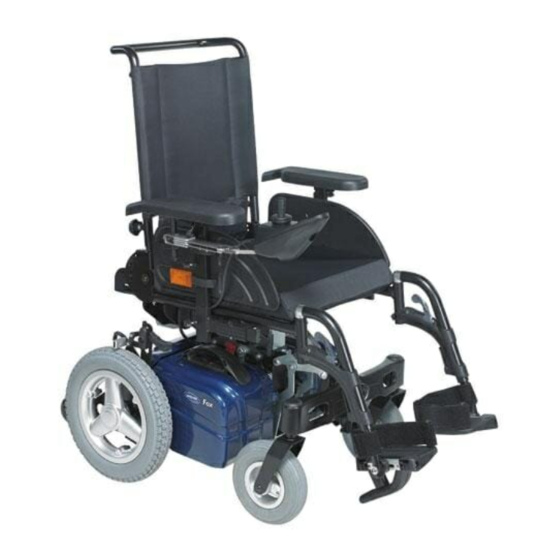
Invacare® Fox™ operate a particular remote, refer to its corresponding user manual 3 Components (enclosed). 3.1 Key features Push bar Remote Legrests Caster locks Curb climber Drive wheel Levers for disengaging motors at the rear (not visible in the picture) 3.2 Remotes... -
Page 19: Getting In And Out Of The Mobility Device
Getting in and out of the mobility device Position your mobility device as close as possible to your seat. 4 Getting in and out of the mobility This might have to be done by an attendant. device Switch your mobility device off. Apply the manual wheel lock of your mobility device (if existing). -
Page 20: Using The Cane Holder
Invacare® Fox™ Folding away the curb climber Pull the lever A on the curb climber to fold it away. Releasing the curb climber Push down the lever of the curb climber to release it. 4.4 Using the cane holder If your mobility device is fitted with a cane holder, it can be used for the safe transport of a walking cane, underarm or forearm crutches. -
Page 21: Driving
Driving 5 Driving NOTE – If installed, make sure to properly adjust and use the postural belt each time you use the wheelchair. CAUTION! Risk of unexpected driving behavior due to locked Sitting comfortably = Driving safely casters If your mobility device is fitted with caster locks and Before each trip, make sure that: these are locked, the casters cannot move freely and •... -
Page 22: Taking Obstacles
Invacare® Fox™ CAUTION! Risk of falling out of the mobility device and damage to the mobility device such as broken casters – Never approach obstacles that are higher than the maximum climbable obstacle height. For the maximum climbable obstacle height, refer to 13 Technical data, page 57. -
Page 23: Driving Up And Down Gradients
If you wish to use your mobility device on public roads and lighting is required by national legislation, then your mobility device needs to be fitted with an appropriate lighting system. Contact your Invacare dealer if you have any questions. 1577074-A... -
Page 24: Pushing The Mobility Device In Freewheel Mode
Invacare® Fox™ 5.6 Pushing the mobility device in freewheel mode The motors of the mobility device are fitted with automatic brakes, preventing that the mobility device starts rolling out of control when the joystick box is switched off. When pushing the mobility device manually whilst freewheeling, the magnetic brakes must be disengaged. -
Page 25: Adjusting The Mobility Device To The User's Seating Posture
Adjusting the mobility device to the user's seating posture 6.2 Adjustment possibility for remote 6 Adjusting the mobility device to the The following information is valid for all seating systems. user's seating posture CAUTION! 6.1 General information on adjusting the Risk of the remote being pushed backwards during an accidental collision with an obstacle, mobility device to the user's seating posture... -
Page 26: Adjusting The Height Of The Remote (Only For Swing-Away Remote Holders)
Invacare® Fox™ 6.3 Adjusting the height of the armrests 6.2.2 Adjusting the height of the remote (only for swing–away remote holders) Requirements: • 1 x 6 mm Allen key Loosen the wing screw A. Loosen the Allen screw A. Set the armrest to the desired height. -
Page 27: Adjusting The Position Of The Armrest In Depth
Adjusting the mobility device to the user's seating posture Loosen screw A. Loosen the screws A and move the armrest in depth. Adjust armrest to required position. Tighten the screws securely. Retighten the screw. 6.6 Adjusting the seat angle Repeat this procedure for the second armrest. CAUTION! 6.5 Adjusting the position of the armrest in Adjusting the seat tilt or the backrest angle... -
Page 28: Adjusting The Backrest Angle
Invacare® Fox™ The backrest is fitted with a stopper allowing you to easily reset the backrest to your preferred backrest angle. Adjusting the backrest is only possible between this angle and smaller angles. If you want to use a larger backrest angle, you need to adjust the stopper. -
Page 29: Adjusting The Backrest Stopper
Adjusting the mobility device to the user's seating posture 6.8 Adjusting the backrest stopper 85° 95° CAUTION! Adjusting the seat tilt or the backrest angle 105° changes the geometry of the mobility device and 115° directly influences its dynamic stability! –... -
Page 30: Adjusting The Headrest
This can cause the neck to be hyperextended during collisions. – It is recommended to use a headrest during transport. The Invacare headrest for this mobility device (available as an option) is the perfect solution for use during transport. – The headrest must be adjusted to the user's ear height. -
Page 31: Adjusting The Height Of The Headrest Or Neckrest
Adjusting the mobility device to the user's seating posture Requirements: • Allen key 5 mm Loosen the knob A. Adjust the headrest or neckrest to the required height. Retighten the knob. Loosen the screws A , B or the clamping lever C. Adjust the headrest or neckrest to the required position. -
Page 32: Types Of Postural Belts
If the belt is only fastened with a bolted connection, ensure that the connection has not loosened or come undone. You can find more information about maintenance work on belts in the service manual, which is available from Invacare. 1577074-A... -
Page 33: Adjusting The Depth Of The Tray / Removing The Tray
Rixen + Kaul KLICKfix system. To this you can attach various The adapter can turn in 90° steps, allowing you to attach an accessory accessories such as the cellphone case supplied by Invacare, which from any of four different directions. Please refer to the installation you can use to transport your cellphone, sports glasses etc. - Page 34 Invacare® Fox™ More information on the KLICKfix system is available at http://www.klickfix.com. 1577074-A...
-
Page 35: Adjusting Footrests And Legrests
Adjusting footrests and legrests Push the release lever inward or outward. The legrest is 7 Adjusting footrests and legrests released. Swivel the legrest inward or outward. 7.1 Standard 80° footrest To remove the legrest simply pull upward. 7.1.1 Swivel the footrests outwards and/or remove 7.1.2 Adjusting the length them Requirements:... -
Page 36: Manually Height-Adjustable Legrest
Invacare® Fox™ 7.2 Manually height-adjustable legrest CAUTION! Risk of injury due to incorrect adjustment of the 7.2.1 Swivelling the legrest outward and/or removing footrests and legrests The unlocking knob is located on the top section of the legrests. – Before and during every journey it is imperative to... -
Page 37: Adjusting The Depth Of The Calf Pad
Adjusting footrests and legrests Requirements: • 1 x 5 mm Allen key Swivel the calf pad to the front. Release bolt (1) with the Allen key and remove. Set the nut on the other side to the required depth. Adjust the calf pad to match the depth of the nut, put the screw back in and tighten. -
Page 38: Adjusting The Height Of The Calf Pad
Invacare® Fox™ 7.2.5 Adjusting the height of the calf pad Loosen the hand screw (1). Adjust to required position. Retighten the wing nuts. 1577074-A... -
Page 39: Electrical System
When the battery indicator reached the red LED range, charge – A defective main fuse may be replaced only after the batteries for 16 hours minimum, neglecting the charge checking the entire electric system. An Invacare complete display! specialised dealer must perform the replacement. You •... -
Page 40: How To Charge The Batteries
– Only ever use the battery charger supplied with your be left unattended during charging. All charging devices which vehicle, or a charger that has been approved by are supplied by Invacare comply with these requirements. Invacare. • You cannot overcharge the batteries when using the charger... -
Page 41: Storage And Maintenance
Electrical system • Switch off the mobility device. Pay attention to the Battery Charge Indicator! Charge the Connect the battery charger to the charger socket. batteries when the Battery Charge Indicator shows that battery Connect the battery charger to the power supply. charge is low. -
Page 42: Transporting Batteries
Invacare® Fox™ • • The depth of discharge affects the cycle life. The harder a Always have your batteries installed by a properly trained battery has to work, the shorter is its life expectancy. mobility device technician. They have the necessary training and Examples: tools to do the job safely and correctly. -
Page 43: Maintenance
9 Maintenance found in the service manual for this device, which can be obtained from Invacare. That manual, however, is intended to be used by 9.1 Maintenance introduction trained and authorized service technicians, and describes tasks which The term “Maintenance“... -
Page 44: Monthly
It is confirmed by stamp and signature that all jobs listed in the inspection schedule of the service and repair instructions have been properly performed. The list of the inspection jobs to be performed can be found in the service manual which is available through Invacare. - Page 45 Maintenance Stamp of authorized dealer / Date / Signature Stamp of authorized dealer / Date / Signature 2nd Annual Inspection 3rd Annual Inspection Stamp of authorized dealer / Date / Signature Stamp of authorized dealer / Date / Signature 4th Annual Inspection 5th Annual Inspection Stamp of authorized dealer / Date / Signature Stamp of authorized dealer / Date / Signature...
-
Page 46: Transport
Invacare® Fox™ 10.2 Transferring the mobility device to a 10 Transport vehicle 10.1 Transport — General information WARNING! The mobility device is in danger of tipping over WARNING! if it is transferred to a vehicle while the driver is Risk of death or serious injury to the mobility... -
Page 47: Locking/Unlocking The Caster Locks
– Make sure the caster locks are unlocked before (UK for example), but may also be obtained from driving. Invacare as an option in other countries. Your mobility device can be fitted with caster locks. These locks This mobility device complies with the requirements of ISO... -
Page 48: How The Mobility Device Is Anchored In A Vehicle For Use As A Vehicle Seat
Invacare® Fox™ It is imperative that the mobility device is inspected by an authorized CAUTION! dealer before being used again after being involved in a crash. Risk of injury or damage to the mobility device or Alterations to the mobility device anchoring points may not be to the transporting vehicle, if the legrests are in a carried out without the manufacturer's permission. -
Page 49: How The User Is Secured Within The Mobility Device
This can cause the neck to be hyperextended during collisions. – It is recommended to use a headrest during transport. The Invacare headrest for this mobility device (available as an option) is the perfect solution for use during transport. – The headrest must be adjusted to the user's ear height. -
Page 50: Disassembling The Mobility Device For Transport
Refer to 10.4.4 Removing/Installing the battery boxes, page 53. • Invacare strongly recommends securing the mobility device to the floor of the transporting vehicle. Proceed as follows to disassemble the mobility device for transport: Remove the legrests. Refer to 7 Adjusting footrests and legrests, page 35. -
Page 51: Folding The Backrest Forwards
Transport 10.4.1 Folding the backrest forwards Remove the seat if necessary. Refer to 10.4.3 Removing/Installing the seat, page 52. You can leave the seat on the mobility device and move the mobility device like a trolley by tipping it on the antitippers. -
Page 52: Disconnecting The Remote
Invacare® Fox™ 10.4.2 Disconnecting the remote Switch off the remote. Pull the plug A of the remote cable to disconnect the remote. 10.4.3 Removing/Installing the seat CAUTION! Risk of strains from lifting heavy parts! – Use proper lifting techniques. On the center post, pull the safety latches A and fold up the seat until the rear safety latch B on the rear post engages. -
Page 53: Removing/Installing The Battery Boxes
Transport Installing the seat Put the seat on the bracket. Fold the seat forward. Make sure the safety latches on the center post engage. 10.4.4 Removing/Installing the battery boxes CAUTION! Risk of strains from lifting heavy parts! – Use proper lifting techniques. On the battery box, press down the safety latch A and pull the Turn the front wheels at right angle to the driving direction battery box up. -
Page 54: Folding/Unfolding The Chassis
Invacare® Fox™ 10.5 Reassembling the mobility device Connect the battery box and install it. Repeat STEP 1 for the other battery box. Proceed as follows to reassemble the mobility device: Make sure the safety latches A of the battery boxes engage. -
Page 55: After Use
Electric components and printed circuit boards are disposed of as electronic scrap. • Exhausted or damaged batteries can be returned to your medical equipment supplier or Invacare. • Disposal must be carried out in accordance with the respective national legal provisions. -
Page 56: Troubleshooting
Invacare® Fox™ 12 Troubleshooting 12.1 Resetting the circuit breaker WARNING! – NEVER defeat or bypass the circuit breaker. – ONLY replace with a circuit breaker of the same rating. Resetting the circuit breaker may be needed if the mobility device does not turn on and the reset button has popped out about 6 mm. -
Page 57: Technical Data
Technical data 13 Technical data 13.1 Technical specifications The technical information provided hereafter applies to a standard configuration or represents maximum achievable values within the general tolerances. These can change if accessories are added. The precise changes to these values are detailed in the sections for the respective accessories. Permissible operating and storage conditions •... - Page 58 Invacare® Fox™ Caster tires • Tire type 200x50 puncture-proof Driving characteristics • Speed 3 km/h • 6 km/h • Min. braking distance 400 mm (3 km/h) • 1000 mm (6 km/h) • Max. safe slope **** 6° (10.5 %) according to manufacturer’s specifications with 127 kg payload, 4° seat angle, 15°...
- Page 59 Technical data Dimensions in accordance with ISO 7176–15 • Total length (without standard legrests) 747 mm (short wheelbase) • 773 mm (extended wheelbase) • Seat height ** 480/510 mm • Seat width (armrest adjustment range in parentheses) 350 mm (350 - 390 mm) •...
- Page 60 Measured without seat cushion The actual curb weight depends on the fittings your mobility device has been supplied with. Every Invacare mobility device is weighed when leaving the works. Refer to the nameplate for the curb weight (including batteries) measured.
- Page 61 Notes...
- Page 62 Notes...
- Page 63 Notes...
- Page 64 Invacare Sales Companies Australia: Ireland: New Zealand: Canada: Invacare Australia PTY. Ltd. Invacare Corporation Invacare Ireland Ltd, Invacare New Zealand Ltd 1 Lenton Place, North Rocks N.S.W. 570 Matheson Blvd E Unit 8 Unit 5 Seatown Business Campus 4 Westfield Place, Mt Wellington,...