Table of Contents
Advertisement
Advertisement
Table of Contents

Related Manuals for UNI-T UT161 Series


Summary of Contents for UNI-T UT161 Series
- Page 1 P/N:110401109612X UT161 Series 1000V True RMS Digital Multimeter User Manual...
- Page 2 Preface Thank you for purchasing this brand new product. In order to use this product safely and correctly, please read this manual thoroughly, especially the safety notes. After reading this manual, it is recommended to keep the manual at an easily accessible place, preferably close to the device, for future reference.
-
Page 3: Table Of Contents
I. Overview The UT161B/UT161D/UT161E is a handheld true RMS digital multimeter with high reliability and security (UT161B/UT161D: 6000 counts; UT161E: 22000 counts). With large screen, high resolution analog pointer display, full scale overload protection, and unique appearance design, it becomes a new practical Table of Contents electrical measuring meter. -
Page 4: Safety Instructions
III. Safety Instructions IV. Electrical Symbols The meter is designed and manufactured according to IEC61010-1 safety standard, and conforms to CAT III 1000V, CAT IV 600V, and pollution degree 2. If the meter Symbol Description is used in a manner not specified by the manufacturer, the protection provided by the meter may be impaired. -
Page 5: External Structure
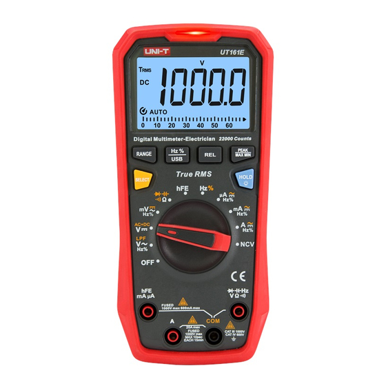
VI. LCD Display (Picture 2, Picture 3) V. External Structure (Picture 1) 1. NCV detector 2. Indicator light 3. LCD display 4. Function buttons 5. Function dial 6. Input terminals Picture 2 UT161B/UT161D Picture 3 UT161E 7. USB (Bluetooth) access port Description Symbol 8. -
Page 6: Function Dial And Function Buttons
VII. Function Dial and Function Buttons 2. Function Buttons Short press: Press a button for less than 2s. 1. Function Dial Long press: Press a button for more than 2s. Description Dial Position Button Power off Short press to switch between functions in each compound function position. AC voltage measurement/Low pass filter measurement/ Frequency and duty ratio measurement (UT161E) Button... -
Page 7: Operating Instructions
Before each use, verify meter operation by measuring a known voltage. VIII. Operating Instructions The input impedance of the meter is about 10MΩ. This load effect may cause Please check the internal batteries first. If “ ” is displayed, replace the batteries measurement errors in high-impedance circuits. - Page 8 The input impedance of the DC mV range is infinite (about 1GΩ), and it does 3. AC/DC Millivolt Voltage Measurement (Picture 6) not attenuate when measuring weak signals, so the measurement accuracy is high. When the test leads are open, there may be a value on the screen, but this is normal and will not affect the measuring result.
- Page 9 5. Resistance Measurement (Picture 8) 6. Continuity Test (Picture 9) Picture 8 Picture 9 1) Insert the red test lead into the terminal, and black test lead into the COM terminal. 1) Insert the red test lead into the terminal, and black test lead 2) Turn the function dial to the position.
- Page 10 7. Diode Test (Picture 10) 8. Capacitance Measurement (Picture 11) Picture 10 Picture 11 1) Insert the red test lead into the terminal, and black test lead into the COM terminal. 1) Insert the red test lead into the terminal, and black test lead 2) Turn the function dial to the position.
- Page 11 9. Transistor Magnification (hFE) Measu rement 10. Frequency/Duty Ratio Measurement (Picture 13) (UT161E, Picture 12) Picture 12 Picture 13 1) Turn the function dial to the hFE position. 2) Insert the adapter socket into the input terminals. 1) Insert the red test lead into the terminal, and black test lead 3) Insert the three pins of the transistor under test into the corresponding holes into the COM terminal.
- Page 12 11. Temperature Measurement (UT161D, Picture 14) 12. AC/DC Current Measurement (Picture 15) AC/DC Digital Multimeter-HVAC FUSED 1000V max MAX 10sec EACH 15min Picture 15 1) Insert the red test lead into the mA/μA or A terminal, and black test lead into Picture 14 the COM terminal.
- Page 13 13. Non-Contact Voltage (NCV) Detection (Picture 16) 14. USB Data Transmission (Picture 17a, Picture 17b) Picture 17b Digital Multimeter-HVAC Picture 17a 1) Pull out the USB sealing cover at the back of the meter (Picture 17a). 2) Insert the USB communication module into the USB access port of the meter and the LCD will display “...
-
Page 14: Specifications
2. Electrical Specifications IX. Specifications Accuracy: ± (a% of reading + b digits), 1 year warranty Ambient temperature: 23°C ± 5°C (73.4°F ± 9°F) Relative humidity: ≤75% 1. General Specifications Caution: 1) Max voltage between the input terminal and COM terminal: Please refer to the To ensure measurement accuracy, the operating temperature should be within description of input protection voltage for each range. - Page 15 a) Add 4% when crest factor is 1~2 2) AC Voltage b) Add 5% when crest factor is 2~2.5 UT161E c) Add 7% when crest factor is 2.5~3 Range Frequency response Accuracy Resolution The AC crest factor can be ≤2.0 at 10000 counts, and can only be ≤1 at ±...
- Page 16 5) Continuity and Diode 4) Resistance UT161B/UT161D/UT161E UT161E Range Resolution Remarks Range Accuracy Resolution Broken circuit: Resistance ≥70Ω, no beep 220.00Ω 0.01Ω 0.1Ω Well-connected circuit: Resistance <50Ω, 2.2000kΩ 0.1Ω audio/visual alarm ± (0.5+10) 22.000kΩ 1Ω Open circuit voltage: About 3V 220.00kΩ...
- Page 17 9) DC Current UT161B/UT161D UT161E Range Accuracy Resolution Range Accuracy Resolution 60.00nF 10pF 220.00μA 0.01μA 100pF 600.0nF 2200.0μA 0.1μA ± (0.5%+10) 6.000μF ± (3%+5) 1μA 22.000mA 60.00μF 10nF 220.00mA 10μA 600.0μF 100nF ± (1.2%+50) 20.000A 6.000mF 1μF ± (10%+5) 10μF 60.00mF UT161B/UT161D Overload protection: 1000V...
- Page 18 10) AC Current a) Add 4% when crest factor is 1~2 b) Add 5% when crest factor is 2~2.5 UT161E c) Add 7% when crest factor is 2.5~3 Range Frequency response Accuracy Resolution The AC crest factor can be ≤2.0 at 10000 counts, and can only be ≤1 at ±...
-
Page 19: Maintenance
12) Indicator Light 4) Resistance measurement can be used to check the built-in 600mA and 11A fuses. Operation (Picture 18a): Insert the red test lead into the Description Function Status terminal.Insert the red probe into the mA/μA input terminal to measure the <36V resistance.