
Related Manuals for UNI-T UT10A


Summary of Contents for UNI-T UT10A
-
Page 1: Table Of Contents
Model UT10A: OPERATING MANUAL Table of Contents (1) Table of Contents Title Page Overview Unpacking Inspection Safety Information Rules For Safe Operation International Electrical Symbols The Meter Structure Functional Buttons Measurement Operation A. DC Voltage Measurement B. AC Voltage Measurement C. - Page 2 Model UT10A: OPERATING MANUAL Table of Contents (2) Title Page Sleep Mode General Specifications Accuracy Specifications A. DC Voltage B. AC Voltage C. Resistance Test D. Frequency E. Duty Cycle F. Diodes and Continuity Test G. Capacitance Maintenance A. General Service B.
-
Page 3: Overview
Model UT10A: OPERATING MANUAL Overview Overview Warning To avoid electric shock or personal injury, read the “Safety Information” and “Rules for Safety Operation” carefully before using the Meter. Pocked-Sized Digital Multimeter Model UT10A (hereafter referred to as “the Meter”) is a 3 3/4 digits with steady operations, fashionable structure, low power consumption and highly reliable hand-held measuring instrument. -
Page 4: Unpacking Inspection
Model UT10A: OPERATING MANUAL Unpacking Inspection Unpacking Inspection Open the package case and take out the Meter. Check the following items carefully to see any missing or damaged part: Item Description English Operating Manual 1 piece Built-In Test Lead 1 pair Vinyl Holder 1 piece 3V Button Battery (CR2032) -
Page 5: Safety Information
Model UT10A: OPERATING MANUAL Safety Information Safety Information This Meter complies with the standards IEC61010: in pollution degree 2, overvoltage category (CAT. II 300V) and double insulation. CAT. II: Local level, appliance, PORTABLE EQUIPMENT etc., with smaller transient voltage overvoltages than CAT. III Use the Meter only as specified in this operating manual, otherwise the protection provided by the Meter may be impaired. -
Page 6: Rules For Safe Operation
Model UT10A: OPERATING MANUAL Rules For Safe Operation (1) Rules For Safe Operation Warning To avoid possible electric shock or personal injury, and to avoid possible damage to the Meter or to the equipment under test, adhere to the following rules: Before using the Meter inspect the case. - Page 7 Model UT10A: OPERATING MANUAL Rules For Safe Operation (2) When the Meter working at an effective voltage over 60V in DC or 30V rms in AC, special care should be taken for there is danger of electric shock. Use the proper terminals, function, and range for your measurements. Do not use or store the Meter in an environment of high temperature, humidity, explosive, inflammable and strong magnetic field.
- Page 8 Model UT10A: OPERATING MANUAL Rules For Safe Operation (3) When servicing the Meter, use only the same model number or identical electrical specifications replacement parts. The internal circuit of the Meter shall not be altered at will to avoid damage of the Meter and any accident.
-
Page 9: International Electrical Symbols
Model UT10A: OPERATING MANUAL International Electrical Symbols International Electrical Symbols Deficiency of Built-In Battery AC (Alternating Current) Capacitance Double Insulated Warning. Refer to the Operating Manual Conforms to Standards of European Union Grounding DC (Direct Current) Diode Continuity Test Fuse... -
Page 10: The Meter Structure
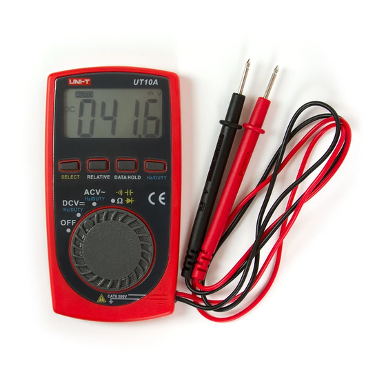
Model UT10A: OPERATING MANUAL The Meter Structure The Meter Structure (see figure 1) 1. LCD Display 2. SELECT Button 3. RELATIVE Mode Button 4. DATA HOLD Button 5. Hz/DUTY Button 6. Rotary Switch 7. Black Test Lead 8. Red Test Lead ( figure 1) -
Page 11: Functional Buttons
Model UT10A: OPERATING MANUAL Functional Buttons Functional Buttons Below table indicated for information about the functional button operations Button Operation Performed Press SELECT to switch between resistance, capacitance, continuity buzzer and SELECT diode measurement modes; the Meter beeps. Resistance measurement is default. -
Page 12: Measurement Operation
Model UT10A: OPERATING MANUAL Measurement Operation(1) Measurement Operation Make sure the Sleep Mode is not on if you found there is no display on the LCD after turning on the Meter. Make sure the Low Battery Display is not on, otherwise false readings may be provided. -
Page 13: Dc Voltage Measurement
Model UT10A: OPERATING MANUAL Measurement Operation(2) A. DC Voltage Measurement (see figure 2) Black ( figure 2) - Page 14 Model UT10A: OPERATING MANUAL Measurement Operation (3) To measure DC voltage, connect the Meter as follows: 1. Set the rotary switch to DCV range. 2. Connect the test leads across with the object being measured with red test lead to the positive and black test lead to the negative. The measured value shows on the display.
-
Page 15: Ac Voltage Measurement
Model UT10A: OPERATING MANUAL Measurement Operation (4) B. AC Voltage Measurement (see figure 2 with dotted line) Warning To avoid harms to you or damages to the Meter from electric shock, please do not attempt to measure voltages higher than 300V although readings may be obtained and take extra care when measuring high voltage. -
Page 16: Measuring Resistance
Model UT10A: OPERATING MANUAL Measurement Operation (5) C. Measuring Resistance (see figure 3) Hz/Duty Black ( figure 3) - Page 17 Model UT10A: OPERATING MANUAL Measurement Operation(6) Warning To avoid damages to the Meter or to the devices under test, disconnect circuit power and discharge all the high-voltage capacitors before measuring resistance. To measure resistance, connect the Meter as follows: 1. Set the rotary switch to range.
- Page 18 Model UT10A: OPERATING MANUAL Measurement Operation(7) For high resistance (>1M ), it is normal taking several seconds to obtain a stable reading. When there is no input, for example in open circuit condition, the Meter displays “OL”. When resistance measurement has been completed, disconnect the connection between the testing leads and the circuit under test.
-
Page 19: Frequency And Duty Cycle Measurement
Model UT10A: OPERATING MANUAL Measurement Operation(8) D. Frequency and Duty Cycle Measurement (see figure 3 with dotted line) Warning To avoid harm to you or damages to the Meter, do not attempt to measure voltages higher than 60V in DC or 30V rms in AC although readings may be obtained. -
Page 20: Measuring Diodes & Continuity
Model UT10A: OPERATING MANUAL Measurement Operation(9) E. Measuring Diodes & Continuity (see figure 3 with dotted line) Warning To avoid damage to the Meter or to the equipment under test, disconnect circuit power and discharge all high-voltage capacitors before measuring diodes and continuity. - Page 21 Model UT10A: OPERATING MANUAL Measurement Operation(10) 2. Press SELECT button to select diode test. 3. For forward voltage drop readings on any semiconductor component, place the red test lead on the component’s anode and place the black test lead on the component’s cathode.
- Page 22 Model UT10A: OPERATING MANUAL Measurement Operation(11) Testing for Continuity To test for continuity, connect the Meter as below: 1. Set the rotary switch to range. 2. Press SELECT button to select continuity test. 3. Connect the test leads across with the object being measured. The buzzer sounds continuously if the resistance of a circuit under test is around less than 70 .
-
Page 23: Capacitance Measurement
Model UT10A: OPERATING MANUAL Measurement Operation(12) F. Capacitance Measurement (see figure 3 with dotted line) Warning To avoid damage to the Meter or to the equipment under test, disconnect the tested circuit power when measuring on line capacitors and discharge all high- voltage capacitors before measuring capacitance. - Page 24 Model UT10A: OPERATING MANUAL Measurement Operation(13) Note For testing the capacitor with polarity, connect the red test lead to anode & black test lead to cathode For measuring capacitance higher than 10 F, it is normal taking several seconds to obtain a reading. When capacitance measurement has been completed, disconnect the connection between the testing leads and the circuit under test.
-
Page 25: Sleep Mode
Model UT10A: OPERATING MANUAL Sleep Mode Sleep Mode To preserve battery life, the Meter automatically turns off if you do not turn the rotary switch or press any button for around 15 minutes. The Meter can be activated by pressing any functional buttons or turning the rotary switch. When the Meter is activated by pressing SELECT button, the Sleep Mode feature will be disabled. -
Page 26: General Specifications
Model UT10A: OPERATING MANUAL General Specifications General Specifications Maximum voltage between any Terminals and Grounding: 300V rms or 300DCV Range: Auto ranging. Maximum Display: 3999. (3 3/4 digits) Mesaurement Speed: Updates 3 times/second. Operating Temperature: 0 C~40 C(32 F~104 F), Relative Humidity: 75 Storage Temperature: -10 C~50 C( 14... -
Page 27: Accuracy Specifications
Model UT10A: OPERATING MANUAL Accuracy Specifications(1) Accuracy Specifications Accuracy: (a% reading + b digits), guarantee for 1 year. Operating temperature: 23 Relative humidity: <75%. Temperature coefficient: 0.1 x (specified accuracy) / 1... -
Page 28: Dc Voltage
Model UT10A: OPERATING MANUAL Accuracy Specifications(2) A. DC Voltage Range Resolution Accuracy Overload Protection Remarks (0.8%+3) 400mV 0.1mV 300V DC Input Impedance: 10M 300V AC. (0.8%+1) 10mV 300V 100mV... -
Page 29: Ac Voltage
Model UT10A: OPERATING MANUAL Accuracy Specifications(3) B. AC Voltage Range Resolution Accuracy Overload Protection Remarks Input Impedance: 10M . Frequency response: (1.2%+3) 300V DC 10mV 40Hz~400Hz. 300V AC. Display effective value of 300V 100mV sine wave (mean value response). -
Page 30: Resistance Test
Model UT10A: OPERATING MANUAL Accuracy Specifications(4) C. Resistance Test Range Resolution Accuracy Overload Protection Remarks (1.2%+2) (1%+2) Open circuit voltage: 250V AC approx. 0.45V 400k (1.2%+2) (1.5%+2) -
Page 31: Frequency
Model UT10A: OPERATING MANUAL Accuracy Specifications(5) D. Frequency Range Resolution Accuracy Overload Protection Remarks The inputted voltage 99.99Hz 0.01Hz is sine wave 999.9Hz 0.1Hz When 10Hz ~10kHz: 250V AC (0.5%+3) 1V rms 9.999kHz 0.001kHz When 10kHz~100kHz: 30V rms. 99.99kHz 0.01kHz... -
Page 32: Duty Cycle
Model UT10A: OPERATING MANUAL Accuracy Specifications(6) E. Duty Cycle Range Resolution Overload Protection Remarks Press Hz/DUTY button at ACV 0.1% ~ range to select Duty Cycle 0.1% 250V AC 99.9% measurement mode. Reading is only for reference, F. Diodes and Continuity Test Function Range Resolution Input Protection... -
Page 33: Capacitance
Model UT10A: OPERATING MANUAL Accuracy Specifications(7) G. Capacitance Range Resolution Accuracy Overload Protection Remarks Reading is only for reference 0.001nF 40nF 0.01nF Open circuit voltage: around 400nF 0.1nF 0.45V (4%+3) 250V AC Measuring under Relative 0.001 F mode. 40 F 0.01 F (5%+10) When the tested capacitor is... -
Page 34: Maintenance
Model UT10A: OPERATING MANUAL Maintenance(1) Maintenance This section provides basic maintenance information including battery and fuse replacement instruction. Warning Do not attempt to repair or service your Meter unless you are qualified to do so and have the relevant calibration, performance test, and service information. To avoid electrical shock or damage to the Meter, do not get water inside the case. -
Page 35: General Service
Model UT10A: OPERATING MANUAL Maintenance(2) A. General Service Periodically wipe the case with damp cloth and mild detergent. Do not use chemical solvent. To clean the terminals with cotton bar with detergent, as dirt or moisture in the terminals can affect readings. Turn the Meter OFF when it is not in use and take out the battery when not using for a long time. -
Page 36: Replacing The Battery
Model UT10A: OPERATING MANUAL Maintenance(3) B. Replacing the Battery (see figure 4) SCREW (figure 4) - Page 37 Model UT10A: OPERATING MANUAL Maintenance(4) Warning To avoid false readings, which could lead to possible electric shock or personal injury, replace the battery as soon as the battery indicator appears. To replace battery: 1. Disconnect the connection between the testing leads and the circuit under test 2.
- Page 38 Model UT10A: OPERATING MANUAL Copyright 2004 Uni-Trend International Limited. All rights reserved. Manufacturer: UNI-TREND TECHNOLOGY(DONG GUAN)LIMITED Address: Dong Fang Da Dao, Bei Shan Dong Fang Industrial Development District, Hu Men Town, Dong Guan City, Guang Dong Province, China Headquarters: Uni-Trend International Limited Address: Rm901, 9/F, Nanyang Plaza 57 Hung To Road Kwun Tong Kowloon, Hong Kong Tel: (852) 2950 9168...