
Related Manuals for UNI-T UT106


Summary of Contents for UNI-T UT106
-
Page 1: Table Of Contents
Model UT106: OPERATING MANUAL Table of Contents Title Page Overview Unpacking Inspection Safety Information Rules For Safe Operation Automotive Servicing Safety Guide International Electrical Symbols The Meter Structure Rotary Switch Functional Buttons Display Symbols Measurement Operation Part 1 Multimeter Basic Testing A. - Page 2 Model UT106: OPERATING MANUAL Title Page F. Trigger Voltage Battery Load Testing G. Voltage Drop Testing H. Charging System Voltage Testing I. Ignition System Testing 1. Ignition Coil Testing 2. Ignition System High Voltage Damper Testing 3. Hall Switch/Sensor Testing 4.
-
Page 3: Overview
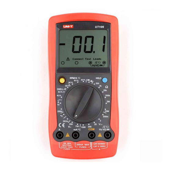
To avoid electric shock or personal injury, read the “Safety Information” and “Rules for Safe Operation” carefully before using the Meter. Automotive Digital Multimeter Model UT106 (hereafter referred to as “the Meter”) is a 1999 counts, 3-1/2 digits manual ranging meter. Spotting a unique design with an extra large LCD display, Connect Test Leads display, full overload protection and unique outlook design. -
Page 4: Unpacking Inspection
Model UT106: OPERATING MANUAL Unpacking Inspection Open the package case and take out the Meter. Check the following items carefully to see any missing or damaged part: Item Description English Operating Manual 1 piece Test Lead 1 pair Point Contact Temperature Probe... -
Page 5: Rules For Safe Operation
Model UT106: OPERATING MANUAL Rules For Safe Operation Warning To avoid possible electric shock or personal injury, and to avoid possible damage to the Meter or to the equipment under test, adhere to the following rules: Before using the Meter inspect the case. Do not use the Meter if it is damaged or the case (or part of the case) is removed. - Page 6 Model UT106: OPERATING MANUAL If the value of current to be measured is unknown, use the maximum measurement position, and reduce the range step by step until a satisfactory reading is obtained Replace the battery as soon as the battery indicator appears.
-
Page 7: Automotive Servicing Safety Guide
Model UT106: OPERATING MANUAL Automotive Servicing Safety Guide Warning As some automobiles are installed with safety air bags, you must pay attention to the cautions in the automotive servicing manual when you are working around the components and wiring of the air bags, or any carelessness will open an air bag, resulting in some personal injury. - Page 8 Model UT106: OPERATING MANUAL All the information, explanations and detailed descriptions in the operation manual have originated from the industrial information recently published. It is impossible to prove the accuracy and completeness of the information, of which we shall not be responsible for the assumption.
-
Page 9: International Electrical Symbols
Model UT106: OPERATING MANUAL International Electrical Symbols AC (Alternating Current). DC (Direct Current) Grounding. Double Insulated. Deficiency of Built-In Battery. Fuse. Warning. Refer to the Operating Manual. Conforms to Standards of European Union. -
Page 10: The Meter Structure
Model UT106: OPERATING MANUAL The Meter Structure (see figure 1) (figure 1) 1. LCD display 2. Data Hold button 3. Rotary Switch 4. Input Terminals 5. Power button... -
Page 11: Rotary Switch
Model UT106: OPERATING MANUAL Rotary Switch Below table indicated for information about the rotary switch positions. Rotary Function Switch Position DC voltage measurement. AC voltage measurement. Resistance measurement. Diode test. Continuity test, Unit: DC Current Measurement. Temperature Measurement, Unit: Frequency Measurement, Unit: Kilohertz... -
Page 12: Display Symbols
Model UT106: OPERATING MANUAL Display Symbols (see figure 2) ( figure 2) The battery is low. Warning: To avoid false readings, which could lead to possible electric shock or personal injury, replace the battery as soon as the battery indicator appears. -
Page 13: Measurement Operation
Model UT106: OPERATING MANUAL Measurement Operation Part 1 Multimeter Basic Testing A. DC Voltage Testing (see figure 3) ( figure 3) Warning To avoid harms to you or damages to the Meter from electric shock, please do not attempt to measure voltages higher than 1000Vp although readings may be obtained. - Page 14 Model UT106: OPERATING MANUAL Note If the value of voltage to be measured is unknown, use the maximum measurement position (1000V) and reduce the range step by step until a satisfactory reading is obtained. The LCD displays “1” indicating the existing selected range is overloaded, it is required to select a higher range in order to obtain a correct reading.
-
Page 15: Av Voltage Testing
Model UT106: OPERATING MANUAL B. AC Voltage Testing (see figure 4) ( figure 4) Warning To avoid harms to you or damages to the Meter from electric shock, please do not attempt to measure voltages higher than 1000Vp although readings may be obtained. - Page 16 Model UT106: OPERATING MANUAL Note If the value of voltage to be measured is unknown, use the maximum measurement position (1000V) and reduce the range step by step until a satisfactory reading is obtained. The LCD displays “1” indicating the existing selected range is overloaded, it is required to select a higher range in order to obtain a correct reading.
-
Page 17: Dc Current Testing
Model UT106: OPERATING MANUAL C. DC Current Testing (see figure 5) ( figure 5) Warning Before connecting the Meter in serial to the tested in-circuit, disconnect in-circuit power. If the fuse burns out during measurement, the Meter may be damaged or the operator himself may be hurt. - Page 18 Model UT106: OPERATING MANUAL Note If the value of current to be measured is unknown, use the maximum measurement position (10A) and 10A terminal, and reduce the range step by step until a satisfactory reading is obtained. When DC current measurement has been completed, disconnect the connection between the testing leads and the circuit under test.
-
Page 19: Resistance Testing
Model UT106: OPERATING MANUAL D. Resistance Testing (see figure 6) ( figure 6) Warning To avoid damages to the Meter or to the devices under test, disconnect circuit power and discharge all the high-voltage capacitors before measuring resistance. To avoid harm to yourselves , never attempt to input an effective voltage over 60V in DC or 30V in AC. - Page 20 Model UT106: OPERATING MANUAL Note The test leads can add 0.1 to 0.2 of error to the resistance measurement. To obtain precision readings in low-resistance, that is the range of 200 , short- circuit the input terminals beforehand and record the reading obtained (called this reading as X).
-
Page 21: Diode Testing
Model UT106: OPERATING MANUAL E. Diode Testing (see figure 7) ( figure 7) Warning To avoid possible damage to the Meter and to the device under test, disconnect circuit power and discharge all high-voltage capacitors before testing diodes and continuity. - Page 22 Model UT106: OPERATING MANUAL Note In a circuit, a good diode should still produce a forward voltage drop reading of 0.5V to 0.8V; however, the reverse voltage drop reading can vary depending on the resistance of other pathways between the probe tips.
-
Page 23: Continuity Testing
Model UT106: OPERATING MANUAL F. Continuity Testing (see figure 7) Warning To avoid possible damage to the Meter and to the device under test, disconnect circuit power and discharge all high-voltage capacitors before testing diodes and continuity. To avoid harm to yourselves , never attempt to input an effective voltage over 60V in DC or 30V in AC. -
Page 24: Temperature Measurement
Model UT106: OPERATING MANUAL G. Temperature Measurement (see figure 8) Black ( figure 8) Warning To avoid harm to yourselves , never attempt to input an effective voltage over 60V in DC or 30V in AC. The temperature measurement range is -40... -
Page 25: Frequency Measurement
Model UT106: OPERATING MANUAL H. Frequency Measurement (see figure 9) ( figure 9) Warning To avoid harm to yourselves , never attempt to input an effective voltage over 60V in DC or 30V in AC. The measurement range is 2kHz. -
Page 26: Dwell Testing
Model UT106: OPERATING MANUAL I. Dwell Testing (see figure 10) Ignition Coil Test Lead Ground Black Test Lead ( figure 10) It was very important in the past to test the dwell of the cut-off switch of an ignition system. The dwell testing means the duration when the cut-off switch remains off when the cam is turning. -
Page 27: Engine Tach (Rotation Speed) Testing "Rpmx10
Model UT106: OPERATING MANUAL J. Engine Tach (Rotation Speed) Testing “RPMx10” (see figure 11) Ignition Coil Test Lead Ground Black Test Lead ( figure 11) The RPM means the rotating frequency of the main shaft of the engine per minute. -
Page 28: Operation Of Hold Mode
Model UT106: OPERATING MANUAL K. Operation of Hold Mode The Hold mode is applicable to all measurement functions: Press HOLD to enter Hold mode Press HOLD again to exit Hold mode In Hold mode, is displayed... -
Page 29: Part 2 Diagnosis Of Automotive Troubles
Model UT106: OPERATING MANUAL Part 2 Diagnosis of Automotive Troubles The Meter UT106 is a tool for the very effective diagnosis of the troubles with the electronic systems of the automobile. This part gives a special introduction as to how the Meter UT106 is used to diagnose any trouble with a fuse, switch, solenoid, relay, starting and charging systems, ignition system, fuel system and engine sensor. -
Page 30: Switch Testing: Check The Switch To See If It Can Work Correctly
Model UT106: OPERATING MANUAL B. Switch Testing: Check the switch to see if it can work correctly. The same as in Items 1 to 3 (Fuse Testing). Connect the black test lead probe to one end of the switch and the red one to another end. When the switch is connected, the reading of the meter should be displayed less than 10 . -
Page 31: Starting/Charging System Testing
Model UT106: OPERATING MANUAL D. Starting/Charging System Testing The on-off package of the engine starting system consists of a battery, engine starting button, solenoid and relay starting buttons, lead connections and lines. During the operation of the engine, the charging system keeps the battery charged. -
Page 32: Battery Power Consumption Testing When The Engine Is Off
Model UT106: OPERATING MANUAL E. Battery Power Consumption Testing when the Engine Is off The test is carried out to find the amperage of the power consumption of the battery when both the ignition key and the engine are off. The test is helpful for the determination of the additional consumption of the battery, which may finally lead to the exhaustion of the battery. -
Page 33: Trigger Voltage Battery Load Testing
Model UT106: OPERATING MANUAL F. Trigger Voltage Battery Load Testing Upon the start of the engine, test the battery to see if it can offer an adequate voltage. Set the rotary switch to 20 VDC. As prompted at the LCD connect terminal, insert the red test lead into the V terminal and the black one into the COM terminal. -
Page 34: Voltage Drop Testing
Model UT106: OPERATING MANUAL G. Voltage Drop Testing Test the voltage drops caused by the switch, cable, solenoid or connector. Any abnormal voltage drop generally results from an additional resistance. The resistance will restrict the currents upon the start of the engine, leading to the reduction of the load voltage of the battery and the slow-down of the start of the engine. - Page 35 Model UT106: OPERATING MANUAL Component Voltage Switch 300 mV Lead 200 mV Grounding 100 mV Battery Lead Connector 50 mV Wiring 0.0 V Compare the readings of the tested voltages against the said table. If the voltage is on the high side, check the components and connectors to see if there is anything wrong.
-
Page 36: Charging System Voltage Testing
Model UT106: OPERATING MANUAL H. Charging System Voltage Testing This testing is used to see if the charging system operates normally so as to provide the electronic systems with adequate power (lamps, electric fans, radio sets, etc.). Set the rotary switch to the 200mV or 2 VDC. As... -
Page 37: Ignition System Testing
Model UT106: OPERATING MANUAL I. Ignition System Testing 1. Ignition Coil Testing Before the operation, cool the engine and cut off the ignition coil. Set the rotary switch to the 200 . As prompted at the LCD connect terminal, insert the red test lead into terminal and the black one into the COM terminal. -
Page 38: Ignition System High Voltage Damper Testing
Model UT106: OPERATING MANUAL Set the rotary switch to the 200k and test the primary coil of the ignition coil. Connect the red test lead probe to the secondary outlet and the black one to the primary “-” pole. Refer to various kinds of automotive manuals for the details. -
Page 39: Hall Switch/Sensor Testing
Model UT106: OPERATING MANUAL Warning Some of Chrysler’s products use a spark plug high voltage damper with “positive lock” end electrodes, which can only be moved out of the distributor board. If it is moved out of anywhere else, some damage will result. -
Page 40: Magnetic Resistance Sensor
Model UT106: OPERATING MANUAL Move the Hall sensor out of the automobile and see the details of the operation in various kinds of automotive manuals. Connect the positive pole of the 9 V battery to the source end of the sensor and the negative pole to... -
Page 41: Rpmx10 Testing
Model UT106: OPERATING MANUAL 5. RPMx10 Testing (see figure 17) Ignition Coil Black Ground (figure 17) Set the rotary switch to RPMx10 and select the number of cylinders in the automobile to be tested. As prompted at the LCD connect terminal, insert the... -
Page 42: Fuel System Testing
Model UT106: OPERATING MANUAL 6. Fuel System Testing It is necessary to add more accurate engine fuel control to a low injection automobile. Since 1980, the automotive manufacturing industry has used electronically-controlled carburetor and fuel injection so as to achieve lower fuel injection. -
Page 43: Engine Sensor Testing
Model UT106: OPERATING MANUAL The testing method is similar to that of the resistance of an ignition coil. Cut the electric link off the injector. (Refer to the servicing handbooks of various kinds of automotive manuals for the detailed position.) Connect the red and black test lead probes to the two ends of the injector. -
Page 44: Oxygen Sensor
Model UT106: OPERATING MANUAL 1. Oxygen Sensor The oxygen sensor is used to test the oxygen content in the exhaust, giving rise to an appropriate voltage or resistance. A low voltage (high resistance) means a too high oxygen content in the exhaust, while a high voltage (low resistance) means a too low oxygen content. - Page 45 Model UT106: OPERATING MANUAL The zirconia sensor is tested with the 2VDC. As prompted at the LCD connect terminal, insert the red test lead into the V terminal and insert the black test lead into the COM terminal. The titania sensor is tested with the 200k . As...
-
Page 46: Temperature Sensor
Model UT106: OPERATING MANUAL 2. Temperature Sensor (see figure 20) Heater Temperature Sensor Black (figure 20) The temperature sensor changes the output resistance through the changes in peripheral temperatures. The hotter the sensor is, the lower the resistance becomes. The temperature sensor is generally used in engine braking, air ventilation, flow, fuel temperature and other equipment. -
Page 47: Absolute Pressure (Map) And Baro Sensor
Model UT106: OPERATING MANUAL The position sensor is an electrometer or variable resistance. It is used for the computer monitoring of the position and direction of a mechanical device. The typical position sensors include throttle, exhaust recirculating EGR, blade air flow and other sensors. - Page 48 Model UT106: OPERATING MANUAL The MAP sensor is used to change a pressure signal into a DC voltage or frequency one. All GM, Chrysler, Honda and Toyota use DC voltage type MAP sensors, while Ford uses frequency type MAP sensors. Refer to relevant manuals for other automotive manufacturers.
-
Page 49: Mass Air Flow (Maf) Sensor
Model UT106: OPERATING MANUAL 5. Mass Air Flow (MAF) Sensor (see figure 23) Ground Black Low frequency MAF Sensor of GM (General Motor) in 1988 or Before (figure 23) The sensor converts the air flow into a DC voltage, low frequency or high frequency signal. - Page 50 Model UT106: OPERATING MANUAL Frequency Type Sensor: In a vacuum state, the displayed value should be 330 RPM 5%. (This only applies to GM low frequency sensors.) The other low frequency sensors shall be based on the parameters furnished by the supplier.)
-
Page 51: General Specifications
Model UT106: OPERATING MANUAL General Specifications Maximum Voltage between any Terminals and grounding: Refer to different range input protection voltage. Fuse Protection of mA C terminal: 315mA, 250V, fast type, 5x20mm Fuse Protection of A terminal: 10A, 250V, fast type, 5x20mm Measurement Speed: Updates 2-3 times /second. -
Page 52: Accurate Specifications
Model UT106: OPERATING MANUAL Accurate Specifications Accuracy: (a% Reading + Digits), guarantee for 1 year. Operating Temperature: 18 C to 28 Relative Humidity: No more than 75% RH. A. DC Voltage Overload Range Resolution Accuracy Protection 230VAC 200mV 0.1 mV 1 mV (0.5%+2) -
Page 53: Dc Current
Model UT106: OPERATING MANUAL C. DC Current Overload Range Resolution Accuracy Protection Fuse 315mA, 250V, 200mA 0.1 mA (0.8%+5) fast type, 5x20mm Fuse 10A, 250V, 10 mA (1.2%+5) fast type, 5x20mm Remark: When measuring 5 to 10A: For continuous measurement 10 seconds and interval time between 2 measurement greater than 15 minutes. -
Page 54: Continuity Testing
Model UT106: OPERATING MANUAL F. Continuity Testing Overload Range Resolution Protection 600Vp Remark: Open circuit voltage approximate 2.7V. The buzzer does not sound when the resistance value is >100 . The circuit is disconnected. The buzzer sounds continuously when the resistance value is 10 . -
Page 55: Dwell Testing
Model UT106: OPERATING MANUAL I. Dwell Testing Overload Range Resolution Accuracy Protection 4CYL 6CYL (3%+5) 600 Vp 8CYL Remark: Input Scope: 10V in forward impulse; Bandwidth 0.5mS J. Tach (Rotation Speed) Testing Overload Range Resolution Accuracy Protection 4CYL 10 RPM... -
Page 56: Maintenance
Model UT106: OPERATING MANUAL Maintenance This section provides basic maintenance information including battery and fuse replacement instruction. Warning Do not attempt to repair or service your Meter unless you are qualified to do so and have the relevant calibration, performance test, and service information. -
Page 57: Replacing The Fuses
Model UT106: OPERATING MANUAL B. Replacing the Fuses (see figure 24) Holster Screw (figure 24) Warning To avoid electrical shock or arc blast, or personal injury or damage to the Meter, use specified fuses ONLY in accordance with the following procedure. -
Page 58: Replacing The Battery
Model UT106: OPERATING MANUAL C. Replacing the Battery (see figure 25) Open up Screw Battery (figure 25) Warning To avoid false readings, which could lead to possible electric shock or personal injury, replace the battery as soon as the battery indicator “... - Page 59 Model UT106: OPERATING MANUAL...
- Page 60 Model UT106: OPERATING MANUAL Copyright 2005 Uni-Trend Group Limited. All rights reserved. Manufacturer: Uni-Trend Technology (Dongguan) Limited Dong Fang Da Dao Bei Shan Dong Fang Industrial Development District Hu Men Town, Dongguan City Guang Dong Province China Postal Code: 523 925...