Advertisement
Quick Links
Advertisement

Related Manuals for UNI-T ut151a


Summary of Contents for UNI-T ut151a
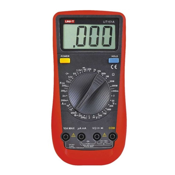
- Page 1 P/N:110401102629...
- Page 2 TABLE OF CONTENTS Item Page I. Characteristics---------------------------------------------------------------------------------------- --------------3 II. Technical data------------------------------------------------------------------------------------------------------ 3 III. Operating method ------------------------------------------------------------------------------------------------9 IV. Maintenance of instrument ---------------------------------------------------------------------- ------------15 V. Accessories -------------------------------------------------------------------------------------------------------17...
- Page 3 OVERVIEW If you want to change the bad fuse and you must use the one of the same type. In order to avoid electric shock, the potential difference between common port COM a nd 3 1/2-bit DDM in the brand-new UT151 series is a kind of hand-held 3 1/2-bit digital earth is not exceeded 1000V.
- Page 4 I.CHARACTERISTICS Accuracy Range Resolution UT151A UT151B UT151C UT151D UT151E 1. There are 30 ranges for function selection. 200mV 100µV 2. LCD display with visible zone 63 29mm 1 mV 3. Over-range indication (0.5%+1) 4. The maximum value displayed of 1999(three and half digits)
- Page 5 Overloading protection: uA, mA input: 200 mA /250V Ö 5 × 20 mm A input end: 10A/250V Ö 6 × 25 mm Accuracy Range Resolution Maximum input current: 10A (For current over 5A, measuring time shall not exceed 15 UT151A UT151B UT151C UT151D UT151E seconds) 200 µA...
- Page 7 2-11 Battery measurement (only for UT151A) 4) Introduction of the instrument: Power switch Range Accuracy Description Resolution LCD display 12 V 10 mV Built-in load resistance: 240Ù Data hold (2.5%+2) 10 mV Built-in load resistance: 1.8 KÙ Functional switch 1.5 V 10 mV Built-in load resistance: 30Ù...
- Page 8 3-1 Measurement of DC voltage 3-3 Measurement of direct current 1. Insert the black pen into the COM hole and the red pen into the V hole. 1. Insert the black pen into the COM hole. When the current for which the maximum value is 2.
- Page 9 Notice Notice 1) Refer to Notice 1, 2 and 3 in the Direct Current Measurement. 1) Although protection to the capacitance shift is set by the instrument, testing shall still be carried out after capacitor discharge to avoid damage to the instrument or causing measuring 3-5 Resistance measurement error.
- Page 10 3-11 Instructions for use of automatic power cut-off c. After the new battery is installed, install the battery cover and tighten the screws. 1. Automatic power cut-off circuit is set for the instrument. When working time of the instrument Screw is about 15min, the power is automatically cut off.
- Page 11 V. ACCESSORIES 1. Operating Guide-------------------------------------------------------One book 2. Pen----------------------------------------------------------------------- One pair 3. Cross point-type thin-line K thermocouple sensor----------- One suit (only for UT151C and UT151E) Content of this manual is subject to changes without notice.