Table of Contents
Advertisement
Advertisement
Table of Contents
Troubleshooting

Related Manuals for Agilent Technologies 5800


Summary of Contents for Agilent Technologies 5800
- Page 1 Agilent 5800 and 5900 ICP-OES User's Guide...
- Page 2 FAR 12.211 (Technical Data) and 12.212 (Computer Software) and, for the Department of Defense, DFARS 252.227-7015 (Technical Data - Commercial Items) and DFARS 227.7202-3 (Rights in Commercial Computer Software or Computer Software Documentation). Agilent 5800 and 5900 ICP-OES User's Guide...
-
Page 3: Table Of Contents
ICP-OES Instrument Cooling Air Supply Water Chiller System Drain Vessel Installation Agilent ICP-OES Instrument Overview Instrument Status LED Color Coding Front Power On/Off Button ICP Expert Software Connecting ICP Expert software to the ICP-OES Agilent 5800 and 5900 ICP-OES User's Guide... - Page 4 Turning on the instrument for the first time (or from long term shutdown) Running the instrument from standby Preparing for Analysis Performing a Detector and Wavelength Calibration Creating/Opening a Worksheet Creating a new worksheet Opening an existing worksheet Agilent 5800 and 5900 ICP-OES User's Guide...
- Page 5 Important Acid soak cleaning procedure for the torch for aqueous or acid-based samples (one piece and semi-demountable torches) Rinsing the torch Drying the torch Additional checks after cleaning Troubleshooting Spare Parts Technical Support Agilent 5800 and 5900 ICP-OES User's Guide...
- Page 6 Contents This page is intentionally left blank. Agilent 5800 and 5900 ICP-OES User's Guide...
-
Page 7: Safety Practices And Hazards
The safety practices described below are provided to help the user operate the instrument safely. Read each safety topic thoroughly before attempting to operate the instrument and always operate the spectrometer in accordance with these safety practices. Agilent 5800 and 5900 ICP-OES User's Guide... -
Page 8: Verifying Safe State
Failure to comply with these precautions or with specific warnings elsewhere in this manual violates safety standards of design, manufacture, and intended use of the instrument. Agilent Technologies assumes no liability for the customer’s failure to comply with these requirements. -
Page 9: Heat, Vapors And Fumes
(except that of air or oxygen) can result in an oxygen-deficient atmosphere, which can cause asphyxiation. The area in which cylinders are stored and the area surrounding the instrument must be adequately ventilated to prevent such gas accumulations. Agilent 5800 and 5900 ICP-OES User's Guide... -
Page 10: Electrical Hazards
Likewise, interrupting the protective conductor inside or outside the Agilent ICP-OES or defeating the power cord ground creates a shock hazard for the operator and can damage the instrument. Agilent 5800 and 5900 ICP-OES User's Guide... -
Page 11: Other Precautions
Great care should be taken when working with glass or quartz parts to prevent breakage and cuts. This is especially important when inserting the nebulizer into the spray chamber or removing and replacing pieces of broken torch. Agilent 5800 and 5900 ICP-OES User's Guide... -
Page 12: Warning Symbols
Disconnect power Broken glass Chemical hazard Extreme cold hazard Electrical shock Eye hazard Heavy weight Heavy weight Fire hazard (danger to feet) (danger to hands) Hot surface Noxious gases RF radiation Agilent 5800 and 5900 ICP-OES User's Guide... - Page 13 Socket for Agilent accessory serial cable Socket for Ethernet LAN cable Socket for Agilent accessory USB cable Indication of correct orientation of gas filter flow direction Caution, disconnect all supplies, risk of electric shock Agilent 5800 and 5900 ICP-OES User's Guide...
- Page 14 Safety Practices and Hazards This page is intentionally left blank. Agilent 5800 and 5900 ICP-OES User's Guide...
-
Page 15: Introduction
Site Preparation Requirements Prior to receiving your instrument, you will have been provided with an Agilent 5800 and 5900 ICP-OES Site Preparation Guide, which describes the environmental and operating requirements of the ICP-OES system. You must prepare your laboratory according to these instructions before the ICP-OES can be installed. -
Page 16: Conventions
The user (or other authorized personnel) must carry out appropriate leak tests necessary to ensure safety on the gas and liquid connections that the operator is directed to assemble during installation, normal use or maintenance. Agilent 5800 and 5900 ICP-OES User's Guide... -
Page 17: Exhaust System
The cooling air system with flue, fan, ducting and supply cowl, must provide positive air pressure at the instrument inlet of 4 m /min (141 ft /min) when using the External Inlet Duct Adaptor Kit. The ducting should be corrosion-resistant and fire-proof. Agilent 5800 and 5900 ICP-OES User's Guide... -
Page 18: Water Chiller System
2 liters (4 pints) of waste must be provided by the user. It should be located underneath the sample compartment (or on the right side of the instrument), where it is protected by the bench and in full view of the operator. Agilent 5800 and 5900 ICP-OES User's Guide... -
Page 19: Installation
An Agilent representative will then arrange a suitable installation date with you. Details for unpacking the instrument and what to do in case it has been damaged in transit are also outlined in the Site Preparation Guide. Agilent 5800 and 5900 ICP-OES User's Guide... -
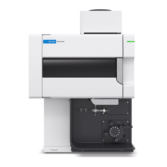
Page 20: Agilent Icp-Oes Instrument Overview
19. Optional AVS 4, AVS 6 or AVS 7 cable connection Switching Valve accessory location 6. Torch 13. Front panel power button 20. Drain for liquid overflow 7. Nebulizer and make up gas 14. LED instrument status connections indicator Agilent 5800 and 5900 ICP-OES User's Guide... - Page 21 (not shown) Optics purge filter Argon or nitrogen gas filter Water outlet Connect to return from the water chiller Water filter Coarse particulate water filter Water inlet Connect to supply from the water chiller Agilent 5800 and 5900 ICP-OES User's Guide...
-
Page 22: Instrument Status Led Color Coding
Green blinking slow (1 Hz). The mains power module is initializing and running through power up self-check, or is shutting off the instrument. Agilent 5800 and 5900 ICP-OES User's Guide... -
Page 23: Icp Expert Software
ICP Expert Software Installation Instructions for 21 CFR Part 11 Environments Once you have installed the appropriate software, connect the Ethernet cable, set the instrument IP address if necessary, and then perform the Detector Calibration and Wavelength Calibration. Agilent 5800 and 5900 ICP-OES User's Guide... -
Page 24: Connecting Icp Expert Software To The Icp-Oes
(for radial or dual view) are installed. Use manual sampling. The recommended peristaltic pump tubing is White/White for the pump and Blue/Blue for the drain. Ignite the plasma. Agilent 5800 and 5900 ICP-OES User's Guide... -
Page 25: Saving And Viewing The Calibration Data
However, you may need to set up items such as the peristaltic pump, nebulizer, torch or spray chamber. For instructions on how to do this, please refer to the ‘How to’ section in the ICP Expert Help and Learning Center. Agilent 5800 and 5900 ICP-OES User's Guide... -
Page 26: Icp-Oes Torches
Short (no slot) Short (no slot) Short (no slot) Outer tube material Quartz Quartz Quartz Intermediate tube Quartz tulip Quartz tulip Quartz tulip Recommended Most sample types Most sample types Hydrofluoric (HF) acid digests application Agilent 5800 and 5900 ICP-OES User's Guide... -
Page 27: Torch Assembly And Disassembly
A fully demountable torch can be adapted for another application by replacing the injector and/or the outer tube with the configuration recommended for that sample type. Refer to the Agilent Technologies website for ordering information. Torch Assembly and Disassembly Both the semi- and fully demountable torch models allow the outer/intermediate tube-set to be separated from the base/injector for easier cleaning or replacement. -
Page 28: Assembly Of The Semi-Demountable Torch
Place the top seal back on the quartz tube-set, slide the clean seal back onto the tube-set from the bottom end, making sure the top flat face of the seal is positioned facing the top of the tube-set. See Figure 4. Agilent 5800 and 5900 ICP-OES User's Guide... - Page 29 “T” alignment mark as shown in Figure 5. Figure 5. The top seal aligned with the alignment mark on the quartz outer tube Agilent 5800 and 5900 ICP-OES User's Guide...
- Page 30 Figure 7. The alignment mark on the quartz outer tube-set should be aligned with the groove on the torch body Press the quartz outer tube-set fully into the torch body and then press down on the top seal to secure the tube-set in place. See Figure 8. Agilent 5800 and 5900 ICP-OES User's Guide...
-
Page 31: Assembly Of The Fully Demountable Torch
Fully insert the injector through the base of the torch body until the bulge contacts the retaining arm and “clicks” into position. Replace the locking nut and tighten to secure the injector. Hand tighten only. Do not overtighten or use a wrench for leverage. CAUTION Agilent 5800 and 5900 ICP-OES User's Guide... -
Page 32: Torch Disassembly
Repeat the action on the opposite slot. The seal should be dislodged from the torch body. Figure 9. Removing the top seal on a semi-demountable torch by prodding it using a thumb nail Agilent 5800 and 5900 ICP-OES User's Guide... - Page 33 Maintaining a straight parallel movement, carefully slide the quartz outer tube- set off the torch body. See Figure 11. Avoid contact between the quartz tube-set and injector Figure 11. Removing the quartz tube-set from the torch body Agilent 5800 and 5900 ICP-OES User's Guide...
- Page 34 Remove the quartz tube-set from the top of the torch base. If the top seal is removed with the quartz outer tube-set, slide the top seal off the tube-set towards the top end. Agilent 5800 and 5900 ICP-OES User's Guide...
-
Page 35: Accessories
The SPS 4 is compatible with a wide range of commercially available low-cost autoclavable sample racks. Sample contamination from airborne particles is eliminated and corrosive or toxic fumes are removed during sampling with the optional environmental enclosure. Agilent 5800 and 5900 ICP-OES User's Guide... -
Page 36: Advanced Valve System (Avs) - Avs 4, Avs 6 And Avs 7
ICP Expert Help. The MSIS is used with the ICP-OES instrument to provide simultaneous vapor generation of several hydride forming elements, enabling determination with low ppb detection limits. Agilent 5800 and 5900 ICP-OES User's Guide... -
Page 37: Argon Humidifier
IsoMist utilizes the Peltier effect to provide electrical cooling or heating to the spray chamber. The ‘Set Temperature’ is monitored and controlled via the ICP Expert software. The IsoMist performance can be monitored and controlled from a lab PC via USB or Bluetooth wireless technology. Agilent 5800 and 5900 ICP-OES User's Guide... - Page 38 Installation This page is intentionally left. Agilent 5800 and 5900 ICP-OES User's Guide...
-
Page 39: Operation
Turn on the PC, instrument and software Connect the software to the instrument Prepare for analysis Perform a dark current scan and wavelength calibration Create/open a worksheet Agilent 5800 and 5900 ICP-OES User's Guide... -
Page 40: Turning On The Instrument And Software
Network. 11 Switch on the computer, monitor and printer. 12 Plug the ICP-OES cable into the wall socket and set the mains power switch on the left side of the instrument to ‘On’. Agilent 5800 and 5900 ICP-OES User's Guide... -
Page 41: Running The Instrument From Standby
If you have accessories fitted, switch them on. Preparing for Analysis To prepare for analysis: Click the Plasma button in the ICP Expert software. Alternatively, press F5 or choose Plasma on from the arrow under the Plasma button. Agilent 5800 and 5900 ICP-OES User's Guide... -
Page 42: Performing A Detector And Wavelength Calibration
Performing a Detector and Wavelength Calibration See Page 24 for instructions. Creating/Opening a Worksheet Creating a new worksheet To create a new worksheet, click New Quantitative or IntelliQuant Screening from the Start page or the File menu. Agilent 5800 and 5900 ICP-OES User's Guide... -
Page 43: Opening An Existing Worksheet
On the ‘Elements’ page, select the element(s) from the ‘Element’ drop-down box or type the element name or symbol and then perform one of the following: Click Add Analyte to add the primary wavelength for the selected element. Agilent 5800 and 5900 ICP-OES User's Guide... - Page 44 12 If you are using an autosampler, click the ‘Autosampler’ tab to select the racks and probe depth (if needed). Depending on the autosampler selected, options may vary. Agilent 5800 and 5900 ICP-OES User's Guide...
-
Page 45: Running Samples
Choose whether you want to print or preview the report or save the report as a PDF file. Previewing the report allows you to ensure that you have included all of the data you require. Select a report template and then click Open. Agilent 5800 and 5900 ICP-OES User's Guide... -
Page 46: Turning Off The Instrument
This Standby Mode option leaves the 5800/5900 ICP-OES in a state of readiness while only consuming low amount of utilities (argon gas and electricity). The benefit of being in Standby Mode is the 5800/5900 can be operational again in <20 minutes from plasma ignition. Standby Mode is automatically enabled once the previous analysis is finished and the plasma is shut down. -
Page 47: Setting The Instrument To Standby Mode With Argon On Or Off
To do this: Push up the pressure bar screws. This releases them from the pressure bar (refer to Figure 13). Allow the pressure bar to swing downwards. Lift the tubing out of the grooves. Agilent 5800 and 5900 ICP-OES User's Guide... -
Page 48: Turning Off The Instrument For Long Term Shutdown
Inhalation danger. The exhaust system MUST remain on if the gas supplies are on. Turning off the instrument for long term shutdown For extended periods of disuse, fully shutdown the instrument. This turns off all purging as well as the polychromator thermostatting system). Agilent 5800 and 5900 ICP-OES User's Guide... - Page 49 If the instrument is not going to be in use for a period of time the torch, cone, snout NOTE and torch compartment should be cleaned of any deposits, dirt or residue. Check the cleanliness of the removable axial window when cone is removed. Agilent 5800 and 5900 ICP-OES User's Guide...
- Page 50 Operation This page is intenionally blank. Agilent 5800 and 5900 ICP-OES User's Guide...
-
Page 51: Maintenance And Troubleshooting
Shock Hazard WARNING This instrument contains electrical circuits, devices and components operating at dangerous voltages. Contact with these circuits, devices and components can result in death, cause serious injury, or painful electrical shock. Agilent 5800 and 5900 ICP-OES User's Guide... -
Page 52: Routine
Check exhaust system and argon gas pressure. Check the water level in the Argon Humidifier before every use (if applicable). Clean the surface of your ICP-OES (spills should be cleaned up immediately). Agilent 5800 and 5900 ICP-OES User's Guide... - Page 53 Perform a wavelength calibration. Inspect the external gas supply system for leaks including the tubing connected to the instrument, and stress cracks. Replace any damaged, leaking or worn components. Agilent 5800 and 5900 ICP-OES User's Guide...
-
Page 54: Cleaning
Torch Cleaning To help you achieve the maximum usable life from all models of the 5800/5900 ICP-OES Easy-fit torch, it is recommended that the cleaning procedures are followed as soon as any discoloration appears on the outer tube of the torch. -
Page 55: Important
Use a clean, wide diameter, open-top beaker (preferably 100 mL tall form) or a similar container to hold the soak solutions. Use the recommended torch cleaning stand (see Figure 15A) for 5800/5900 ICP-OES Easy-fit torches (part number G8010-68021) to hold the torch inverted while soaking during the cleaning process. -
Page 56: Acid Soak Cleaning Procedure For The Torch For Aqueous Or Acid-Based Samples (One Piece And Semi-Demountable Torches)
(Figure 15D). Pipette some of the acid through the ball joint of the injector to remove build- up from the lower part of the injector. See Figure 16A. Agilent 5800 and 5900 ICP-OES User's Guide... - Page 57 Keep the one-piece torch inverted through all the cleaning and rinsing steps unless otherwise directed. Figure 15A. Soak the torch in the aqua regia solution. Ensure the injector is immersed in the solution. Agilent 5800 and 5900 ICP-OES User's Guide...
- Page 58 Rinse the torch and outer tube-set thoroughly and dry completely prior to using the torch in the instrument. Follow the steps outlined below for “Rinsing the torch” and “Drying the torch” listed below. Agilent 5800 and 5900 ICP-OES User's Guide...
-
Page 59: Rinsing The Torch
1 minute. Figure 16A. Rinse the injector with deionized water through the ball joint connector. Agilent 5800 and 5900 ICP-OES User's Guide... - Page 60 Figure 17A and B. Rinse the quartz outer tube-set and top seal with deionized water. Dry the torch completely and re-assemble the semi-demountable torch if necessary, prior to using the torch on the instrument. Agilent 5800 and 5900 ICP-OES User's Guide...
-
Page 61: Drying The Torch
See Figure 18A and Figure 18B. Figure 18A and B. Use compressed air, argon or nitrogen to dry the torch. Agilent 5800 and 5900 ICP-OES User's Guide... -
Page 62: Additional Checks After Cleaning
Perform the following checks after cleaning: Inspect the torch for damage such as loose fitting of the quartz tubes in the plastic base, holes or significant cracks. If any damage is found, replace the torch immediately. Agilent 5800 and 5900 ICP-OES User's Guide... -
Page 63: Troubleshooting
For spare parts and consumables ordering information, refer to the Agilent Technologies website: www.agilent.com To replace the items listed below, you must use Agilent-manufactured parts, which can be ordered online from the Agilent website or through your local sales representative. Agilent 5800 and 5900 ICP-OES User's Guide... -
Page 64: Technical Support
Radial pre-optic window Spray chamber Nebulizer Peristaltic pump tubing Drain tubing Technical Support For technical support contact information, refer to the Agilent Technologies website for details: www.agilent.com Agilent 5800 and 5900 ICP-OES User's Guide... - Page 66 The manual describes the following: The manual describes the following: Safety Practices and Hazards Introduction Installation Operation Maintenance and Troubleshooting www.agilent.com © Agilent Technologies, Inc. © Agilent Technologies 2019 Edition 1, 10/2019 *G8020-90002* G8020-90002...